EP4528207A1 - Anordnung für eine feuerwaffe - Google Patents
Anordnung für eine feuerwaffe Download PDFInfo
- Publication number
- EP4528207A1 EP4528207A1 EP24201235.9A EP24201235A EP4528207A1 EP 4528207 A1 EP4528207 A1 EP 4528207A1 EP 24201235 A EP24201235 A EP 24201235A EP 4528207 A1 EP4528207 A1 EP 4528207A1
- Authority
- EP
- European Patent Office
- Prior art keywords
- generally tubular
- muzzle
- locking
- adapter
- assembly
- Prior art date
- Legal status (The legal status is an assumption and is not a legal conclusion. Google has not performed a legal analysis and makes no representation as to the accuracy of the status listed.)
- Pending
Links
Images









Classifications
-
- F—MECHANICAL ENGINEERING; LIGHTING; HEATING; WEAPONS; BLASTING
- F41—WEAPONS
- F41A—FUNCTIONAL FEATURES OR DETAILS COMMON TO BOTH SMALLARMS AND ORDNANCE, e.g. CANNONS; MOUNTINGS FOR SMALLARMS OR ORDNANCE
- F41A21/00—Barrels; Gun tubes; Muzzle attachments; Barrel mounting means
- F41A21/32—Muzzle attachments or glands
- F41A21/325—Mountings for muzzle attachments
-
- F—MECHANICAL ENGINEERING; LIGHTING; HEATING; WEAPONS; BLASTING
- F41—WEAPONS
- F41A—FUNCTIONAL FEATURES OR DETAILS COMMON TO BOTH SMALLARMS AND ORDNANCE, e.g. CANNONS; MOUNTINGS FOR SMALLARMS OR ORDNANCE
- F41A21/00—Barrels; Gun tubes; Muzzle attachments; Barrel mounting means
- F41A21/30—Silencers
-
- F—MECHANICAL ENGINEERING; LIGHTING; HEATING; WEAPONS; BLASTING
- F41—WEAPONS
- F41A—FUNCTIONAL FEATURES OR DETAILS COMMON TO BOTH SMALLARMS AND ORDNANCE, e.g. CANNONS; MOUNTINGS FOR SMALLARMS OR ORDNANCE
- F41A21/00—Barrels; Gun tubes; Muzzle attachments; Barrel mounting means
- F41A21/32—Muzzle attachments or glands
Definitions
- the invention relates to an assembly for a firearm as defined in the preamble of independent claim 1.
- the object of the invention is to provide an assembly for a muzzle of a barrel of a firearm, which assembly can quickly and reliably be fastened to the muzzle of the barrel of the firearm.
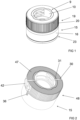
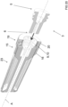
- the assembly 1 has preferably, but not necessarily, a longitudinal central axis A.
- the assembly 1 comprises a generally tubular clutch collar 19 having a third tubular body 20, a fourth proximal end 21, and a fourth distal end 22.
- the assembly 1 comprises a device 23 such as a sound suppressor, a blank firing bullet trap, or a reinforcement bar cutter having a fifth proximal end 24.
- a device 23 such as a sound suppressor, a blank firing bullet trap, or a reinforcement bar cutter having a fifth proximal end 24.
- the muzzle device 3 is configured to be releasably received in the generally tubular muzzle adapter 9 so that co-operating rotation prevention means 26 of the muzzle device 3 and at least one of the device 23 and the generally tubular attachment mount 15prevents the muzzle device 3 from rotating with respect to the device 23 and/or to the generally tubular muzzle adapter 9 about the longitudinal central axis A.
- the muzzle device 3 can, as in the embodiment of the assembly illustrated in figures 19 to 23 , be configured to be releasably received in the generally tubular muzzle adapter 9 so that the first distal end 6 of the muzzle device 3 extends into the fifth proximal end 24 of the device 23.
- the co-operating rotation prevention means 26 are preferably, but not necessarily, formed at least partly of tines 49 of the muzzle device 3 and by recesses 50 in the device 23 sized and shaped for complementary receipt of at least a portion of the tines 49 of the muzzle device 3, as in the embodiment of the assembly illustrated in figures 19 to 23 .
- the generally tubular muzzle adapter 9 is attached to the generally tubular clutch collar 19 for rotation about the longitudinal central axis A together with the generally tubular clutch collar 19 and by means of the tubular clutch collar 19 with respect to the device 23, to the muzzle device 3 and to the generally tubular attachment mount 15 between
- the assembly can for example be configured to be used and be configured to function as presented in the following:
- the muzzle device 3 is fastened to the barrel 4 of the firearm 2.
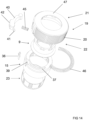
- the generally tubular muzzle adapter 9, the generally tubular attachment mount 15, and the generally tubular clutch collar 19 as well as other parts of the assembly are assembled together, if not already assembled together.
- the device 23 is attached to the generally tubular attachment mount 15.
- the muzzle device 3 is brought into the generally tubular muzzle adapter 9 of the assembly 1 from the second proximal end 11 of the generally tubular muzzle adapter 9.
- the generally tubular muzzle adapter 9 is manually or automatically rotated about the longitudinal central axis A with the generally tubular clutch collar 19 from the unlocking position into the locking position, where successive locking teeth 7 of the muzzle device 3 are in the direction of the longitudinal central axis A at least partly aligned with the locking lugs 13 of the generally tubular muzzle adapter 9 so as to prevent relative movement between the muzzle device 3 and the generally tubular muzzle adapter 9 in the direction of the longitudinal central axis A.
- the openable and closable locking means 36 can for example, as illustrated in the figures, comprise a sliding member (not marked with a reference numeral) that is movable arranged in a groove (not marked with a reference numeral) provided in the generally tubular attachment mount 15.
- the attachment means 25 can for example as in the embodiment of the assembly illustrated in figures 25 to 27 comprise an inner threading 58 on the second tubular body 16 of the generally tubular attachment mount 15 and an outer threading 59 on the device 23 for co-operation with the inner threading 58 on the second tubular body 16 of the generally tubular attachment mount 15.
- An openable and closable locking means 36 (not illustrated in the figures 25 to 27 ) for locking the device 23 in position with respect to the generally tubular attachment mount 15, when the device 23 is releasable attached to the generally tubular attachment mount 15 by means of the outer threading 59 and the inner threading 58 of the attachment means 25 is preferably, but not necessarily, provided.
- the attachment means 25 can for example comprise an outer threading (not illustrated in the figures) on the second tubular body 16 of the generally tubular attachment mount 15 and an inner threading (not illustrated in the figures) on the device 23 for co-operation with the outer threading on the second tubular body 16 of the generally tubular attachment mount 15.
- An openable and closable locking means 36 for locking the device 23 in position with respect to the generally tubular attachment mount 15, when the device 23 is releasable attached to the generally tubular attachment mount 15 by means of the outer threading and the inner threading of the attachment means 25 is preferably, but not necessarily, provided.
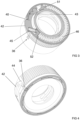
- An arc-shaped groove 37 is preferably, but not necessarily, as in some of the embodiments of the assembly 1 illustrated in the figures, provided in an end surface 38 at the second proximal end 11 of the generally tubular attachment mount 15, wherein the arc-shaped groove 37 has a locking recess 39.
- a spring arm 40 with a locking nose 41 and a button 42 is preferably, but not necessarily, as in some of the embodiments of the assembly 1 illustrated in the figures, pivotally connected to the third inner surface 43 of the generally tubular clutch collar 19 so that the button 42 of the spring arm 40 extends through an opening 44 in the third tubular body 20 of the generally tubular clutch collar 19.
- the spring arm 40 is preferably, but not necessarily, pivotally connected to the third inner surface 43 of the generally tubular clutch collar 19 at a seat (not marked with a reference numeral) provided at to the third inner surface 43 of the generally tubular clutch collar 19.
- a first spring 45 is preferably, but not necessarily, as in some of the embodiments of the assembly 1 illustrated in the figures, provided and configured to press the button 42 of the spring arm 40 through the opening 44 in the third tubular body 20 of the generally tubular clutch collar 19.
- the locking nose 41 of the spring arm 40 is configured to move in the arc-shaped groove 37 in the end surface 38 of the generally tubular attachment mount 15 when the generally tubular muzzle adapter 9 together with the generally tubular clutch collar 19 is rotated about the longitudinal central axis A with respect to the generally tubular attachment mount 15, to the muzzle device 3, and to the device 23 between the locking position and the unlocking position.
- Rotating of the generally tubular muzzle adapter 9 together with the generally tubular clutch collar 19 with respect to the generally tubular attachment mount 15, to the muzzle device 3, and to the device 23 about the longitudinal central axis A is prevented by rotating the generally tubular muzzle adapter 9 together with the generally tubular clutch collar 19 with respect to the generally tubular attachment mount 15 into the locking position resulting in that the locking nose 41 of the spring arm 40 enters the locking recess 39 of the arc-shaped groove, and wherein the locking nose 41 of the spring arm 40 can be brough out of the locking recess 39 of the arc-shaped groove 37 by pressing the button 42 of the spring arm 40.
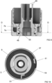
- the assembly 1 comprises preferably, but not necessarily, a second spring 46 that is configured to be loaded when the generally tubular clutch collar 19 together with the circular muzzle adapter 9 is rotated about the longitudinal central axis A with respect to the circular attachment mount 15, to the muzzle device 3, and to the device 23 in direction away from the locking position.
- Such second spring 46 can, as illustrated in figures 3 and 13 to 15 , be a compression spring that is provided between a first abutment 51 provided at the second proximal end 11 of the generally tubular attachment mount 15 and a second abutment 52 provided at the third inner surface 43 of the generally tubular clutch collar 19 and that is configured to be compressed and loaded with energy when the when the generally tubular clutch collar 19 together with the circular muzzle adapter 9 is rotated about the longitudinal central axis A with respect to the circular attachment mount 15, to the muzzle device 3, and to the device 23 in direction away from the locking position.
- Said energy that is loaded into the second spring 46 is configured to rotate the generally tubular clutch collar 19 together with the circular muzzle adapter 9 about the longitudinal central axis A with respect to the circular attachment mount 15, to the muzzle device 3, and to the device 23 back to the locking position or back towards the locking position.
- the generally tubular clutch collar 19 has preferably, but not necessarily, a second radially inwardly projecting flange 47 at the fourth proximal end 21.
- Said number of successive locking teeth 7 and first channels 8 around the outer circumference of the muzzle device 3 comprises preferably, but not necessarily, successive locking teeth of a first locking teeth type 7a and first channels 8 around the outer circumference of the muzzle device 3 at a first axial location of the muzzle device 3 and successive locking teeth of a second locking teeth type 7b and first channels 8 around the outer circumference of the muzzle device 3 at a second axial location of the muzzle device 3, wherein the locking teeth 7 of the first locking teeth type 7a and the locking teeth 7 of the second locking teeth type 7b are separated by a first groove 53 in the axial direction of the muzzle device 3 and wherein the locking teeth 7 of the first locking teeth type 7a have a design that differs from the design of the locking teeth 7 of the second locking teeth type 7b.
- Said number of successive locking lugs 13 and second channels 14 around the inner circumference of the generally tubular muzzle adapter 9 comprises preferably, but not necessarily, successive locking lugs of a first locking lugs type 13a and second channels 14 around the inner circumference of generally tubular muzzle adapter 9 at a first axial location of the generally tubular muzzle adapter 9 and successive locking lugs of a second locking lugs type 13b and second channels 14 around the inner circumference of the generally tubular muzzle adapter 9 at a second axial location of the generally tubular muzzle adapter 9, wherein the locking lugs 13 of the first locking lugs type 13a and the locking lugs 13 of the second locking lugs type 13b are separated by a second groove 54 in the axial direction of the generally tubular muzzle adapter 9, and wherein the locking lugs 13 of the first locking lugs type 13a have a design that differs from the design of the locking lugs 13 of the second locking lugs type 13b.
- the locking teeth 7 of the first locking teeth type 7a have a design and the locking teeth 7 of the second locking teeth type 7b have a design that prevents one of the locking teeth 7 of the first locking teeth type 7a and the locking teeth 7 of the second locking teeth type 7b from entering the second groove 54 but that allows the other of locking teeth 7 of the first locking teeth type 7a and the locking teeth 7 of the second locking teeth type 7b to enter the second groove 54 when the muzzle device 3 is rotated with respect to the generally tubular muzzle adapter 9 about the longitudinal central axis A.
- the locking lugs 13 of the first locking lug type 13a have a design and the locking lugs 13 of the second locking lug type 13b have a design that prevents one of the locking lugs 13 of the first locking lug type 13a and the locking lugs 13 of the second locking lug type 13b from entering the first groove 53 but that allows the other of the locking lugs 13 of the first locking lug type 13a and the locking lugs 13 of the second locking lug type 13b to enter the first groove 53 when the muzzle device 3 is rotated with respect to the generally tubular muzzle adapter 9 about the longitudinal central axis A.
- a purpose of this is to ensure correct connection between the generally tubular muzzle adapter 9 and the muzzle device 3.
- the second distal end 12 of the generally tubular muzzle adapter 9 can be received in the generally tubular attachment mount 15 and the second proximal end 11 of the generally tubular muzzle adapter 9 can be received in the generally tubular clutch collar 19.
- the second distal end 12 of the generally tubular muzzle adapter 9 can be surrounded by the generally tubular attachment mount 15 and the second proximal end 11 of the generally tubular muzzle adapter 9 can be surrounded by the generally tubular clutch collar 19.
- the third proximal end 17 of the generally tubular attachment mount 19 can be received in the generally tubular clutch collar 19.
- the second tubular body 16 of the generally tubular attachment mount 15 can, as illustrated in the figures, have at the third proximal end 17 of the generally tubular attachment mount 15 a shoulder 55 at the outer surface of the second tubular body 16 of the generally tubular attachment mount 15 and an outer surrounding guiding surface 56 at the outer surface of the second tubular body 16 of the generally tubular attachment mount 15 between the shoulder 55 and the third proximal end 17 of the generally tubular attachment mount 15, wherein the fourth distal end 22 of the generally tubular clutch collar 19 abuts the shoulder 55, and wherein an inner surrounding guiding surface 57 of the third tubular body 20 at the fourth distal end 22 of the third tubular body 20 of the generally tubular clutch collar 19 circumferentially abuts the outer surrounding guiding surface 56 at the outer surface of the second tubular body 16 of the generally tubular attachment mount 15.
- At least one of the muzzle device 3, the generally tubular muzzle adapter 9, the generally tubular attachment mount 15, the generally tubular clutch collar 19, and the device 23 is preferably, but not necessarily, made of metal or is preferably, but not necessarily, at least partly made of metal.
Landscapes
- Engineering & Computer Science (AREA)
- General Engineering & Computer Science (AREA)
- Mechanical Operated Clutches (AREA)
Applications Claiming Priority (1)
| Application Number | Priority Date | Filing Date | Title |
|---|---|---|---|
| FI20236038A FI131115B1 (en) | 2023-09-20 | 2023-09-20 | Assembly for a firearm |
Publications (1)
| Publication Number | Publication Date |
|---|---|
| EP4528207A1 true EP4528207A1 (de) | 2025-03-26 |
Family
ID=92882648
Family Applications (1)
| Application Number | Title | Priority Date | Filing Date |
|---|---|---|---|
| EP24201235.9A Pending EP4528207A1 (de) | 2023-09-20 | 2024-09-19 | Anordnung für eine feuerwaffe |
Country Status (3)
| Country | Link |
|---|---|
| US (1) | US12560396B2 (de) |
| EP (1) | EP4528207A1 (de) |
| FI (1) | FI131115B1 (de) |
Families Citing this family (1)
| Publication number | Priority date | Publication date | Assignee | Title |
|---|---|---|---|---|
| US12546551B2 (en) * | 2024-03-26 | 2026-02-10 | Killer Innovations, Inc. | Muzzle assembly for a firearm |
Citations (4)
| Publication number | Priority date | Publication date | Assignee | Title |
|---|---|---|---|---|
| US20160102935A1 (en) * | 2014-10-08 | 2016-04-14 | Gemini Technologies | Quick connect for pistol suppressor |
| EP2805125B1 (de) * | 2012-01-16 | 2016-12-07 | Silencerco, LLC | Schalldämpfersystem für feuerwaffe |
| WO2019102510A1 (en) * | 2017-11-22 | 2019-05-31 | Daffara Giovanni | Coupling device for a firearm accessory |
| US20210199401A1 (en) * | 2016-03-25 | 2021-07-01 | Todd A. Magee | Silencer mount |
Family Cites Families (27)
| Publication number | Priority date | Publication date | Assignee | Title |
|---|---|---|---|---|
| US4893426A (en) * | 1988-10-07 | 1990-01-16 | South Central Research Corp. | Lugged coupling apparatus |
| US20120272818A1 (en) * | 2003-11-06 | 2012-11-01 | Surefire, Llc | Suppressor with crenelated front |
| US8091462B2 (en) | 2009-06-11 | 2012-01-10 | Surefire, Llc | Firearm attachment locking system |
| US7676976B2 (en) * | 2003-11-06 | 2010-03-16 | Surefire, Llc | Systems for attaching a noise suppressor to a firearm |
| US7905170B1 (en) * | 2007-07-18 | 2011-03-15 | Advanced Armament Corp., Llc | Flash suppressor |
| US20110197487A1 (en) * | 2010-02-17 | 2011-08-18 | Timothy Humston | Device to attach a sound suppressor to a firearm |
| US8490535B1 (en) * | 2010-08-20 | 2013-07-23 | Fn Manufacturing, Llc | Flash and sound suppressor for a firearm |
| US9121656B1 (en) * | 2014-08-25 | 2015-09-01 | Thomas McKenzie | Firearm suppressor adapter system |
| US10480888B2 (en) * | 2014-12-26 | 2019-11-19 | Sturm, Ruger & Company, Inc. | Silencer for firearm |
| US9791234B2 (en) * | 2015-10-02 | 2017-10-17 | Thunder Beast Arms Corporation | Locking mechanism for suppressor mount |
| US10883787B2 (en) * | 2015-10-02 | 2021-01-05 | Thunder Beast Aims Corporation | Locking mechanism for suppressor mount |
| US9921021B1 (en) * | 2015-12-29 | 2018-03-20 | Rugged Design, Inc. | Firearm attachment locking systems and methods |
| US10619962B1 (en) * | 2017-02-28 | 2020-04-14 | Ted Hatfield | Sound suppressor for a firearm |
| DK3514475T3 (da) | 2018-01-23 | 2021-07-26 | A Tec Holding As | Koblingselement |
| US10801796B2 (en) * | 2018-05-16 | 2020-10-13 | Sig Sauer, Inc. | Quick disconnect mount for muzzle attachments |
| US10969187B2 (en) * | 2018-10-09 | 2021-04-06 | Smith & Wesson Inc. | Inertial decoupler for firearm sound suppressor |
| US20210348869A1 (en) * | 2020-01-17 | 2021-11-11 | Ryan Joel Kmetz | Quick-detach suppressor adapter |
| US11486670B1 (en) * | 2020-04-23 | 2022-11-01 | Seraph Enterprises, Inc. | Quick disconnect system for muzzle devices |
| US11408702B2 (en) * | 2020-06-16 | 2022-08-09 | Austin Reis-Green | Firearm muzzle accessory coupling device, system and method |
| US12163750B2 (en) * | 2021-02-12 | 2024-12-10 | James Norman Griffitts | Sound suppressor with adapter for use with muzzle accessory |
| US11740047B2 (en) * | 2021-10-22 | 2023-08-29 | Shanyao Lee | Firearm muzzle attachment mechanism |
| US12320605B2 (en) * | 2021-11-02 | 2025-06-03 | Bert John WILSON | Connector for a firearm accessory |
| US12085351B2 (en) * | 2022-01-18 | 2024-09-10 | Austin Reis Green | Muzzle accessory mounting system |
| US20230296344A1 (en) * | 2022-03-15 | 2023-09-21 | Rugged Design, Inc. | Firearm suppressor with secondary retention system |
| US12313361B2 (en) * | 2022-08-17 | 2025-05-27 | Smith & Wesson Inc. | Muzzle mount assembly |
| US20240142191A1 (en) * | 2022-10-31 | 2024-05-02 | Silencerco, Llc | Muzzle device adapter system |
| US12546551B2 (en) * | 2024-03-26 | 2026-02-10 | Killer Innovations, Inc. | Muzzle assembly for a firearm |
-
2023
- 2023-09-20 FI FI20236038A patent/FI131115B1/en active
-
2024
- 2024-09-19 US US18/890,085 patent/US12560396B2/en active Active
- 2024-09-19 EP EP24201235.9A patent/EP4528207A1/de active Pending
Patent Citations (4)
| Publication number | Priority date | Publication date | Assignee | Title |
|---|---|---|---|---|
| EP2805125B1 (de) * | 2012-01-16 | 2016-12-07 | Silencerco, LLC | Schalldämpfersystem für feuerwaffe |
| US20160102935A1 (en) * | 2014-10-08 | 2016-04-14 | Gemini Technologies | Quick connect for pistol suppressor |
| US20210199401A1 (en) * | 2016-03-25 | 2021-07-01 | Todd A. Magee | Silencer mount |
| WO2019102510A1 (en) * | 2017-11-22 | 2019-05-31 | Daffara Giovanni | Coupling device for a firearm accessory |
Also Published As
| Publication number | Publication date |
|---|---|
| US20250093121A1 (en) | 2025-03-20 |
| US12560396B2 (en) | 2026-02-24 |
| FI20236038A1 (en) | 2024-10-09 |
| FI131115B1 (en) | 2024-10-09 |
Similar Documents
| Publication | Publication Date | Title |
|---|---|---|
| EP3705835B1 (de) | Kupplung | |
| US5685102A (en) | Snap-on firearm adapter | |
| EP4528207A1 (de) | Anordnung für eine feuerwaffe | |
| US9739560B1 (en) | System, method and apparatus for attaching an accessory to a firearm | |
| US10996015B2 (en) | Firearm adapter | |
| US6948415B2 (en) | System for attaching a noise suppressor to a firearm | |
| US11766800B2 (en) | Quick connect mechanism for a draw stud assembly | |
| US8147173B2 (en) | Adapter for operating a keyhole saw on a driving machine | |
| US10302384B1 (en) | Firearm barrel fitment sleeve and method of use | |
| US20030155763A1 (en) | Coupling for connecting hydraulic ducts | |
| DE102016000437A1 (de) | Einrichtung zum lösbaren Befestigen eines Schalldämpfers und Schalldämpferanordnung | |
| US12455136B2 (en) | Quick take-down firearm | |
| EP3514475B1 (de) | Kopplungselement | |
| US20240247517A1 (en) | Door handle assembly | |
| US10302388B1 (en) | Handguard attachment mechanism | |
| EP4377579B1 (de) | Stangenverbinder mit hohlstift | |
| US20260085904A1 (en) | Firearm attachable bullet trap | |
| US11913741B2 (en) | Firearm with secured firing pin retaining pin | |
| CN114731014B (zh) | 包括多部分可旋转套筒的电插头的联接半部件,以及电插头和方法 | |
| NO343967B1 (en) | Apparatus for fastening a device onto a barrel of a firearm | |
| US20220187042A1 (en) | Deformable spacer for firearms | |
| WO2000001999A1 (en) | Locking a bolt action - barrel connection |
Legal Events
| Date | Code | Title | Description |
|---|---|---|---|
| PUAI | Public reference made under article 153(3) epc to a published international application that has entered the european phase |
Free format text: ORIGINAL CODE: 0009012 |
|
| STAA | Information on the status of an ep patent application or granted ep patent |
Free format text: STATUS: THE APPLICATION HAS BEEN PUBLISHED |
|
| AK | Designated contracting states |
Kind code of ref document: A1 Designated state(s): AL AT BE BG CH CY CZ DE DK EE ES FI FR GB GR HR HU IE IS IT LI LT LU LV MC ME MK MT NL NO PL PT RO RS SE SI SK SM TR |
|
| STAA | Information on the status of an ep patent application or granted ep patent |
Free format text: STATUS: REQUEST FOR EXAMINATION WAS MADE |
|
| 17P | Request for examination filed |
Effective date: 20250926 |