EP4528228A1 - Interrogateur pour détection à fibre optique distribuée avec sources de charge optique variables - Google Patents
Interrogateur pour détection à fibre optique distribuée avec sources de charge optique variables Download PDFInfo
- Publication number
- EP4528228A1 EP4528228A1 EP23306548.1A EP23306548A EP4528228A1 EP 4528228 A1 EP4528228 A1 EP 4528228A1 EP 23306548 A EP23306548 A EP 23306548A EP 4528228 A1 EP4528228 A1 EP 4528228A1
- Authority
- EP
- European Patent Office
- Prior art keywords
- optical
- light
- probe
- load
- optical fiber
- Prior art date
- Legal status (The legal status is an assumption and is not a legal conclusion. Google has not performed a legal analysis and makes no representation as to the accuracy of the status listed.)
- Pending
Links
Images




Classifications
-
- G—PHYSICS
- G01—MEASURING; TESTING
- G01D—MEASURING NOT SPECIALLY ADAPTED FOR A SPECIFIC VARIABLE; ARRANGEMENTS FOR MEASURING TWO OR MORE VARIABLES NOT COVERED IN A SINGLE OTHER SUBCLASS; TARIFF METERING APPARATUS; MEASURING OR TESTING NOT OTHERWISE PROVIDED FOR
- G01D5/00—Mechanical means for transferring the output of a sensing member; Means for converting the output of a sensing member to another variable where the form or nature of the sensing member does not constrain the means for converting; Transducers not specially adapted for a specific variable
- G01D5/26—Mechanical means for transferring the output of a sensing member; Means for converting the output of a sensing member to another variable where the form or nature of the sensing member does not constrain the means for converting; Transducers not specially adapted for a specific variable characterised by optical transfer means, i.e. using infrared, visible, or ultraviolet light
- G01D5/32—Mechanical means for transferring the output of a sensing member; Means for converting the output of a sensing member to another variable where the form or nature of the sensing member does not constrain the means for converting; Transducers not specially adapted for a specific variable characterised by optical transfer means, i.e. using infrared, visible, or ultraviolet light with attenuation or whole or partial obturation of beams of light
- G01D5/34—Mechanical means for transferring the output of a sensing member; Means for converting the output of a sensing member to another variable where the form or nature of the sensing member does not constrain the means for converting; Transducers not specially adapted for a specific variable characterised by optical transfer means, i.e. using infrared, visible, or ultraviolet light with attenuation or whole or partial obturation of beams of light the beams of light being detected by photocells
- G01D5/353—Mechanical means for transferring the output of a sensing member; Means for converting the output of a sensing member to another variable where the form or nature of the sensing member does not constrain the means for converting; Transducers not specially adapted for a specific variable characterised by optical transfer means, i.e. using infrared, visible, or ultraviolet light with attenuation or whole or partial obturation of beams of light the beams of light being detected by photocells influencing the transmission properties of an optical fibre
- G01D5/35306—Mechanical means for transferring the output of a sensing member; Means for converting the output of a sensing member to another variable where the form or nature of the sensing member does not constrain the means for converting; Transducers not specially adapted for a specific variable characterised by optical transfer means, i.e. using infrared, visible, or ultraviolet light with attenuation or whole or partial obturation of beams of light the beams of light being detected by photocells influencing the transmission properties of an optical fibre using an interferometer arrangement
- G01D5/35309—Mechanical means for transferring the output of a sensing member; Means for converting the output of a sensing member to another variable where the form or nature of the sensing member does not constrain the means for converting; Transducers not specially adapted for a specific variable characterised by optical transfer means, i.e. using infrared, visible, or ultraviolet light with attenuation or whole or partial obturation of beams of light the beams of light being detected by photocells influencing the transmission properties of an optical fibre using an interferometer arrangement using multiple waves interferometer
- G01D5/35316—Mechanical means for transferring the output of a sensing member; Means for converting the output of a sensing member to another variable where the form or nature of the sensing member does not constrain the means for converting; Transducers not specially adapted for a specific variable characterised by optical transfer means, i.e. using infrared, visible, or ultraviolet light with attenuation or whole or partial obturation of beams of light the beams of light being detected by photocells influencing the transmission properties of an optical fibre using an interferometer arrangement using multiple waves interferometer using a Bragg gratings
-
- G—PHYSICS
- G01—MEASURING; TESTING
- G01D—MEASURING NOT SPECIALLY ADAPTED FOR A SPECIFIC VARIABLE; ARRANGEMENTS FOR MEASURING TWO OR MORE VARIABLES NOT COVERED IN A SINGLE OTHER SUBCLASS; TARIFF METERING APPARATUS; MEASURING OR TESTING NOT OTHERWISE PROVIDED FOR
- G01D5/00—Mechanical means for transferring the output of a sensing member; Means for converting the output of a sensing member to another variable where the form or nature of the sensing member does not constrain the means for converting; Transducers not specially adapted for a specific variable
- G01D5/26—Mechanical means for transferring the output of a sensing member; Means for converting the output of a sensing member to another variable where the form or nature of the sensing member does not constrain the means for converting; Transducers not specially adapted for a specific variable characterised by optical transfer means, i.e. using infrared, visible, or ultraviolet light
- G01D5/32—Mechanical means for transferring the output of a sensing member; Means for converting the output of a sensing member to another variable where the form or nature of the sensing member does not constrain the means for converting; Transducers not specially adapted for a specific variable characterised by optical transfer means, i.e. using infrared, visible, or ultraviolet light with attenuation or whole or partial obturation of beams of light
- G01D5/34—Mechanical means for transferring the output of a sensing member; Means for converting the output of a sensing member to another variable where the form or nature of the sensing member does not constrain the means for converting; Transducers not specially adapted for a specific variable characterised by optical transfer means, i.e. using infrared, visible, or ultraviolet light with attenuation or whole or partial obturation of beams of light the beams of light being detected by photocells
- G01D5/353—Mechanical means for transferring the output of a sensing member; Means for converting the output of a sensing member to another variable where the form or nature of the sensing member does not constrain the means for converting; Transducers not specially adapted for a specific variable characterised by optical transfer means, i.e. using infrared, visible, or ultraviolet light with attenuation or whole or partial obturation of beams of light the beams of light being detected by photocells influencing the transmission properties of an optical fibre
- G01D5/35338—Mechanical means for transferring the output of a sensing member; Means for converting the output of a sensing member to another variable where the form or nature of the sensing member does not constrain the means for converting; Transducers not specially adapted for a specific variable characterised by optical transfer means, i.e. using infrared, visible, or ultraviolet light with attenuation or whole or partial obturation of beams of light the beams of light being detected by photocells influencing the transmission properties of an optical fibre using other arrangements than interferometer arrangements
- G01D5/35354—Sensor working in reflection
- G01D5/35358—Sensor working in reflection using backscattering to detect the measured quantity
- G01D5/35361—Sensor working in reflection using backscattering to detect the measured quantity using elastic backscattering to detect the measured quantity, e.g. using Rayleigh backscattering
-
- G—PHYSICS
- G01—MEASURING; TESTING
- G01H—MEASUREMENT OF MECHANICAL VIBRATIONS OR ULTRASONIC, SONIC OR INFRASONIC WAVES
- G01H9/00—Measuring mechanical vibrations or ultrasonic, sonic or infrasonic waves by using radiation-sensitive means, e.g. optical means
- G01H9/004—Measuring mechanical vibrations or ultrasonic, sonic or infrasonic waves by using radiation-sensitive means, e.g. optical means using fibre optic sensors
Definitions
- the present disclosure relates to distributed optical sensing and apparatus for use therein.
- Optical fibers can be used as distributed sensors.
- an optical interrogating device sends a sequence of suitably prepared optical probe pulses into an optical fiber and measures parts of the optical pulses that are returned back to the interrogator by reflectors distributed along the optical fiber
- the reflectors are typically either approximately randomly formed during fabrication of the optical fiber (e.g. causing Raleigh scattering) or are intentionally formed therein (e.g. fiber Bragg gratins, "FBGs").
- Applications of such sensors include but are not limited to detection and/or mapping of ambient disturbances, such as naturally occurring or man-induced mechanical vibrations, temperature and/or pressure variations, etc., both in marine and terrestrial environments.
- Example marine applications relate to monitoring of submarine, power, and telecom cables.
- EP4160941 entitled “Distributed Sensing and Monitoring Using Amplified Optical Links”, describes distributed sensing along an amplified multi-span optical fiber link by providing wavelength-selective optical loopback paths in the optical repeaters thereof.
- An aspect of the present disclosure provides an apparatus.
- the apparatus comprises an optical interrogator for distributed optical fiber sensing comprising an optical transmitter, an optical receiver, and first and second load light sources.
- the load light sources are connected to transmit temporally varying load light to an optical output of the optical interrogator.
- the optical transmitter is connected to transmit probe light to the same optical output such that the temporally varying load light from the first load light source occupies a wavelength range on an opposite side of a wavelength range of the optical probe light as the temporally varying load light from the second load light source.
- Wavelengths of the temporally varying load light are in an amplification range for rare-earth doped amplifiers.
- the multi-span optical fiber line may include optical amplifiers connecting different spans thereof.
- the apparatus may be configured to use a train of probe pulses of different wavelengths to interrogate different spans of the optical fiber line, and to further use correspondingly modulated load light to suitably load the amplifiers.
- optical fiber sensing may be useful for distributed optical fiber sensing along relatively long optical fiber lines that use multiple optical fiber amplifiers (OFAs), such as rare-earth doped OF As s, e.g., erbium-doped OF As, and/or Raman amplifiers, to compensate for optical loss in each optical fiber span or segment thereof.
- OFAs optical fiber amplifiers
- the distributed optical fiber sensing operates by transmitting interrogating, or probe, optical signals along the optical fiber line and analyzing resulting back-scattered light, e.g. due to the Raleigh back-scattering on random imperfections in optical fibers.
- OFAs erbium-doped fiber amplifiers
- OSNR optical signal to noise ratio
- the accumulation of non-linear distortion of the interrogating optical signal may become significant when propagating through a long chain of OF As and transmission fibers. Furthermore, some of the non-linear effects described above may couple the OFA-induced optical power transients into the optical phase of the back-reflected signal being sensed, which would further complicate the sensing.
- FIG. 1 illustrates an interrogating apparatus 100 for distributed optical fiber sensing ("apparatus 100").
- the apparatus 100 may be used, e.g., for detecting vibrations and/or changes in environmental conditions along an optical fiber (OF) line 163 of an optical system 160 ("system 160").
- the OF line 163 of the optical system 160 may include serially connected optical amplifiers (OAs) 165, e.g. rear-earth OF As; examples of such systems include amplified multi-span optical fiber lines such as the cable systems described in the European patent application EP4160941 , or optical fiber systems illustrated in FIGs. 5 and 7 .
- OAs optical amplifiers
- the apparatus 100 is configured to perform distributed optical fiber sensing (DOFS), e.g., distributed acoustic sensing (DAS) measurements, using optical probe signals 131 ("probe light 131").
- DOFS distributed optical fiber sensing
- the apparatus 100 may be configured to perform OTDR measurements and/or interferometric measurements, e.g., as known in the pertinent art.
- the apparatus 100 may additionally or alternatively be configured to perform other types of DOFS, such as distributed temperature sensing (DTS), distributed strain sensing (DSS), and distributed temperature, strain sensing (DTSS), and/or estimate the distance to acoustic or vibrational events along the optical fiber line 163.
- DTS distributed temperature sensing
- DSS distributed strain sensing
- DTSS distributed temperature, strain sensing
- the apparatus 100 includes an optical transmitter (Tx) 130 connected to transmit probe light 131 to an optical output 101, and an optical receiver 140 for receiving return light 161 via an optical input 105.
- the apparatus 100 further includes two sources of load light, i.e. a first source (“L1 source”) 110 and a second source (“L2 source”) 120, which outputs are connected to the same optical output 101 of the apparatus 100.
- the L1 and L2 sources are configured to transmit first temporally varying load light 111 and second temporally varying load light 121, respectively, so that the probe light 131 is spectrally between the first and second load light 111, 121.
- Output light 151 of the apparatus 100 thus combines the optical probe signals 131, the first load light 111, and the second load light 121.
- the probe light 131 is pulsed.
- the pump power of the OAs 165 is typically constant.
- an OA 165 may store a large amount of energy between the probe pulses, causing large spikes and ripples in the probe light 131 downstream of the OA.
- the amplitude of these spikes and ripple may increase after passing through subsequent OAs, e.g. in a repeatered, multi-span optical fiber line. Severe spiking may also lead to nonlinear signal degradation through SPM, and possibly also through other non-linear effects such as e.g., modulation instability and/or stimulated Brillouin back scattering.
- the OA-induced amplitude fluctuations may cause phase modulation of the optical probe signal via Kerr nonlinearities in the optical fiber, with a corresponding deterioration of the return optical signal 161.
- the sensitivity of the apparatus 100 to environmental disturbances, e.g. vibrations and acoustic waves, along the system 160 may be reduced.
- the OA-induced spiking may be reduced by loading the OAs with light of a different wavelength range than the probe light, and varying the optical power of the load light in antiphase with the probe light.
- the spiking may be difficult to sufficiently suppress if the probe and load wavelengths are far from each other, since the OA may react differently to light of different wavelengths.
- the difficulty may increase if the optical probe signal can vary in wavelength in a range that is comparable to, e.g. more than a third of, the gain bandwidth of the OA.
- the ratio R P L1 /P L2 of the optical power P L1 of the first load light 111 to the optical power P L2 of the second load light 121, and in some cases their total optical power (P L1 +P L2 ), is changed so that the OA gain at the new central wavelength ⁇ 2 is approximately equal to the OA gain at the central wavelength ⁇ n1 before the change.
- the optical transmitter 130 may at a time instance t 1 generate a probe light 131 1 centered at a wavelength ⁇ 1 , and at a time instance t 2 generate a probe light 131 2 centered at a wavelength ⁇ 2 > ⁇ 1 , i.e. farther away in spectrum from the first load channel and closer to the second load channel 123.
- the load sources 110, 120 may synchronously adjust their optical powers to maintain the gain for the probe light 131 in the OA(s) 165 to be approximately constant.
- a transmission duration t p of each optical probe signal (e.g. 810, FIG. 8A ) at a particular center wavelength is equal or, preferably, somewhat smaller than the ⁇ t , i.e. t p ⁇ ⁇ t , to avoid non-linear interactions between the optical probe signals of different wavelength, such as the FWM, as the probe signals propagate along an optical fiber line.
- the optical probe signals transmitted at consecutive start times may overlap at the edges.
- the spectral bandwidth of the probe light 131 transmitted at each center wavelength is typically much smaller, e.g. by a factor of 10 or more, than a wavelength spacing ⁇ between adjacent ones of the center wavelengths.
- the optical transmitter 130 may repeatedly transmit the set of N optical probe signals with a repeat period T r ⁇ T, each set transmitted over the N wavelength channels.
- the number of different wavelength channels at the output of the optical transmitter 130 may be at least equal to the number of different optical fibers to interrogate, typically in a range from about 5 to about 20.
- optical probe signals of a same wavelength channel may be used to interrogate two or more different optical fibers.
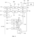
- FIG. 3 illustrates an example implementation 300 of the apparatus 100 of FIG. 1 , which is referred to herein as apparatus 300.
- first and second load light sources 310, 320 are embodiments of the load light sources 110, 120 of the apparatus 100, and are implemented using a common source of white light 307 followed by a corresponding passband drop filters, 311 or 312, and corresponding optical modulators (OMs), 321 or 322, respectively.
- the first drop filter 311 is configured to extract light 313 of a first wavelength range, e.g. 113 in FIG. 1 ; the extracted wavelengths are directed to a first OM 321, which outputs the temporally varying first load light 111.
- the rest of the white light is passed to the second passband filter 312, which is configured to extract therefrom light 323 of a second wavelength range, e.g. 123 in FIG. 1 , and to direct the second extracted wavelengths to a second OM 322, which outputs the temporally varying second load light 121.
- Each of the first and second OMs 321, 322 may be implemented, e.g., as a semiconductor optical amplifier (SOA), conveniently combining optical modulation and amplification functions; other suitable optical modulators, such as but not limited to, e.g., acousto-optic modulators (AOMs), may also be used.
- SOA semiconductor optical amplifier
- AOMs acousto-optic modulators
- the apparatus 300 further includes a multi-channel optical fiber interrogator (OFI) 340 that includes a plurality of N ⁇ 2 channel interrogators (CIs) 330 1 , ..., 330 N , generally referred to herein as CIs 330.
- Each of the CIs 330 includes an optical transmitter (e.g. 410, FIG. 4 ) and an optical receiver (e.g. 420, FIG. 4 ).
- Optical outputs of the CIs 330 connect to an optical wavelength multiplexer (MUX) 325, while optical inputs of the CIs 330 connect to an optical wavelength demultiplexer (DMUX) 326, as indicated in FIG. 3 .
- MUX optical wavelength multiplexer
- DMUX optical wavelength demultiplexer
- the OFI 340 embody the optical transmitter 130 and the optical receiver 140 of the apparatus 100, with the respective optical transmitters and optical receivers of the N CIs 330 together embodying the optical transmitter 130 and the optical receiver 140 of the apparatus 100, respectively.
- each of the CIs 330 n is configured to perform DOFS, e.g., DAS, measurements using optical probe signals of a corresponding probe wavelength channel C n .
- the CIs 330 n generate optical probe signals 332 n of the corresponding probe channels C n , e.g. sequences of suitably shaped optical pulses at respective center wavelengths ⁇ 1 , ..., ⁇ N .
- each of the optical probe signals 332 n which are generated by the corresponding CIs 330 n at corresponding ones of the channel center wavelengths ⁇ 1 , ..., ⁇ N , is a suitably configured optical pulse.
- Each of the CIs 330 n repeatedly transmits this pulse, or a frequency-offset version thereof, with a same repeat period T r within a corresponding wavelength channel.
- each of the optical probe signals 332 n may be a group of two or more consecutive optical pulses repeatedly transmitted with the repeat period T r .
- individual pulses of the group may somewhat differ in the center frequency thereof within the bandwidth of the corresponding wavelength channels.
- the CIs 330 n may time-synchronize to transmit different ones of the optical probe signals 332 n in a time interleaved fashion, so that the output probe light 331 includes a sequence of N optical probe signals of different center wavelengths within the transmission time period T.
- the optical probe signals 332 n are time-multiplexed so that each CI 330 n transmits an optical probe signal, e.g. an optical pulse or a group of optical pulses, at a corresponding one of the start times t k , in a specified order.
- Optical signals transmitted by the CIs 332 n are wavelength-multiplexed by the MUX 325 to obtain an optical probe signal ("probe light") 331, which is directed to an optical output 301 of the apparatus 300.
- the probe light 331 is combined with the L1 light 111 and the L2 light 121, e.g. using add couplers 317 and 319, to form output light 351 of the apparatus 300.
- the probe light 331, the L1 light 111, and the L2 light 121 are spectrally separate from each other, so that each of the add couplers 317, 319 may be implemented with a suitable wavelength multiplexer.
- all of the center wavelengths ⁇ 1 , ..., ⁇ N are within some wavelength range 133 between the wavelength range 113 of the L1 light 111 and the wavelength range 123 of the L2 light, as illustrated in the top insert of FIG. 1 .
- the optical frequencies v n may lie on a non-uniformly spaced frequency grid or a flexible frequency grid.
- the bandwidth B C of ach probe channel C n is defined by a frequency content of the optical probe signals in each probe channel and is much smaller than the inter-channel spacing ⁇ v.
- B C is limited by the speed of used electronic components and optoelectronic components, e.g. ADC and optical modulators, and may be in a 10 MHz to 2 GHz range, 10 to 500 MHz range typically, e.g. about 80 MHz.
- the channel spacing ⁇ v may be in the ⁇ 50GHz to ⁇ 500 GHz range typically.
- the frequency bandwidths of the load light 111, 121 is larger than the bandwidth of the probe light 131 at each center wavelength, and preferably at least as large as the frequency spacing ⁇ v between spectrally-adjacent probe channels.
- the optical frequencies v n may lie close to the center frequencies of an ITU frequency grid.
- the output light 351 is launched into an optical system 360, which may be an embodiment of the optical fiber system 160 and includes an amplified multi-span fiber line. Examples of the system 360 are described herein below with reference to FIGs. 5 (system 580) and FIG. 7 (system 780).
- the optical probe signals of different center wavelengths cause the optical system 360 to generate corresponding optical response signals of the same wavelengths travelling in the return direction, which are received at an optical input 305 of the apparatus 300 as a returned optical signal 355.
- these optical response signals are wavelength-demultiplexed by the DMUX 335 into N demultiplexed returned signals at the corresponding center wavelengths ⁇ 1 to ⁇ N , which are sent to the respective CIs 330 1 - 330 N .
- Each of the CIs 330 1 - 330 N then operates to detect and process the respective received optical response signal, e.g., as known in the pertinent art, to obtain therefrom information related to some aspect(s) of a current state of the system 360 or surroundings thereof, e.g. acoustic and/or vibrational sensing information.
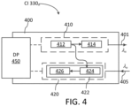
- FIG. 4 shows a schematic block diagram of an example channel interrogator 400 ("CI 400"), which may embody any of the CIs 330 n of the apparatus 300.
- the CI 400 includes an optical transmitter 410 configured to transmit suitably shaped optical probe pulses at a central wavelength ⁇ n , e.g. as may be used to interrogate an optical fiber line.
- the CI 400 further includes an optical receiver 420 configured to receive parts of the pulses returned by the system being interrogated and to perform measurements thereon, e.g. DAS measurements typically including measurements of temporal variations of an optical phase of the received back-scattered light. Results of the measurements are provided to a digital processor 450 to obtain optical fiber sensing information therefrom, e.g. using techniques known in a pertinent art.
- the processor 450 may also be used to control the optical transmitter 410 of the CI 400.
- the processor 450 may be shared with some or all of the CIs used in the system.
- the optical transmitter 410 comprises a laser 412 that is followed by an optical modulator 414, e.g. an AOM, and an optional optical amplifier (not explicitly shown).
- the optical modulator 614 e.g. an acoustic optical modulator (AOM)
- AOM acoustic optical modulator
- the optical probe signal 401 at the output of the OM 414 is a sequence of optical probe pulses that are about 5 ⁇ s to 50 ⁇ s long.
- the pulses may be frequency-modulated ("frequency-chirped"), which enables signal compression at the receiver as known in the art.
- the processor may 450 may operate the OM 414 to monotonically shift ("sweep") the output light in frequency over the duration of each pulse in accordance with a complex modulation function h ( t ) .
- the amount of frequency shift may typically be, e.g. in a range from 5 to 200 MHz over a duration of each pulse.
- the pulses may be linearly frequency modulated, i.e.
- the probe pulses may be suitably apodized, i.e. with desired durations of the rising and falling edges thereof.
- the duration of each of the rising and falling edges of each pulse may be less than 2 ⁇ sec, or preferably about or less than 0.2 ⁇ sec.
- the chirp rate may vary over the duration of a pulse; e.g.
- the chirp rate at the pulse edges may be greater than in a middle portion of the pulse.
- the chirp rate may gradually decrease toward the center of the pulse.
- Non-linearly varying ("sweeping') the optical frequency in this manner may contribute to suppressing compressed-signal side-lobes at the receiver.
- Techniques for generating frequency-chirped pulses using optical modulators, such as e.g. AOM or interferometer-based, are well known in the art.
- the optical probe signals 401 from an output of the optical transmitter 410 may be sent to a MUX, such as e.g. the MUX 325 of the apparatus 300, to be wavelength-multiplexed with corresponding outputs of other instances of the CI 400 centered at a different wavelength, e.g. as described above with reference to FIG. 3 .
- a MUX such as e.g. the MUX 325 of the apparatus 300
- the optical receiver 420 may include an opto-electric (OE) converter 422 followed by an analog-to-digital converter (ADC) (not explicitly shown) that connects to the processor 450.
- the optical receiver 420 may be a coherent optical receiver adapted to make phase-sensitive measurements of the received light, with the processor 450 configured to extract relevant optical phase and/or amplitude information from the measurements.
- the OE converter 422 may include an optical mixer 424, such as e.g. a dual-polarization 90° optical hybrid, to coherently mix the received light with local oscillator light sourced from an output of the laser 412, e.g. separately in two orthogonal polarizations, as known in the art.
- the output(s) of the optical mixer 424 connect to a photodetector circuit 426, which includes one or more photodetectors, e.g. one or more photodiode pairs connected for balanced and/or differential detecting (not explicitly shown), typically followed by one or more trans-impedance amplifiers ("TIAs", not explicitly shown). Electrical signals generated by the photodetector circuit 426 are converted into one or more streams of digital samples and processed in the processor 450 using a suitable signal-processing algorithm to obtain, e.g., acoustic, vibrational, and/or other sensing data along the optical system being tested, e.g. the optical system 360 of FIG. 3 . In various embodiments, such sensing data may be used to detect the presence of mechanical vibrations, fiber faults, localized strain, localized temperature excursions, etc, and/or the location of such environmental events along the optical fiber line.
- TIAs trans-impedance amplifiers
- the digital processor 450 may be configured to process the received streams of digital samples using a matched-filter technique.
- the processor 450 may be configured to obtain a down-converted complex digital representation of the optical field of the received back-scattered light, and compute a convolution of said digital representation with a matched-filter impulse response to obtain a back-scattering response of a corresponding optical fiber.
- the matched-filter impulse response, h *(- t ) is a complex conjugate of the complex modulation h ( t ) applied to the transmitted optical probe signal.
- the processor 450 may be configured to use the well-known "overlap-save" FFT-based convolution algorithm to perform the matched-filter digital signal processing. Techniques to transmit frequency-chirped pulses and to process back scattered signals using filters matched to the transmitted pulses are known in the art..
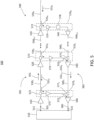
- FIG. 5 illustrates a distributed optical fiber sensing (DOFS) system 500 ("system 500") including an interrogating apparatus 510 and an optical fiber (OF) system 580.
- the interrogating apparatus 510 is connected to the OF system 580 to launch interrogation light 501 therein via an optical output 511, and to receive therefrom a response optical signal 585 via an optical input 515.
- the response optical signal 585 may also be referred to herein as the return light 585.
- the optical fiber system 580 may be, e.g., as described in the European patent application EP4160941 , or a variation thereof.
- Adjacent ones of the OFSs 530 n are end-connected via optical amplifiers (OAs) 520.
- the OAs 520 may be individually adapted to an optical power expected at the input thereof.
- the number N of the optical fiber segments 530 n may be, e.g., between 2 and 100, more typically in a range from 3 to 20.
- the length of each of the optical fiber segments 530 n may be, e.g. in a range from about 10 km to about 120km.
- the OAs 520 are rare-earth doped optical fiber amplifiers (OFAs), such as e.g. erbium-doped fiber amplifiers (EDFA).
- the interrogating apparatus 510 may be an embodiment of the apparatus 100 or the apparatus 300 described above, with the interrogation light 501 including optical probe signals, e.g. 331, and load light, e.g. 111 and 121.
- the apparatus 510 launches the interrogation light 501 into the optical fiber line 581 for sequentially propagating along the N OFSs 530n in a forward direction, i.e., away from the apparatus 510, along the optical fiber line 581.
- the interrogation light 501 Prior to entering each or at least some of the OFSs 530 n , the interrogation light 501 is suitably amplified by a corresponding one of the OAs 520, e.g. to compensate for optical losses in a preceding OFS 530 n-1 .
- Parts of the interrogation light 501 experience back-scattering and/or back-reflections in an OFSs 530n, giving rise to back-scattered light 531 n propagating along the OFS 530 n in a return direction, i.e. back towards the apparatus 510.
- the back-scattered light 531 n may be due to the Raleigh back-scattering on random fiber non-uniformities, or due to intentionally introduced back-reflectors, such as, e.g., fiber Bragg gratings (FBG), which may be incorporated into one or more of the OFS 530 n for the purpose of sensing.
- FBG fiber Bragg gratings
- the back-scattered light 531 n is transmitted back to the apparatus 510, e.g. via a return optical fiber (ROF) line 582, to be received at the apparatus 510 with the return light 585.
- the apparatus 510 is configured to process the return light 585 to obtain sensing data related, e.g., to environmental conditions along the optical fiber line 581.
- Each of the OLB paths 570 n includes a de-coupler 573 located at or near an input end of the respective OFS 530 n to de-couple the corresponding back-scattered light 531 n from the OF line 581, and may further include an optional optical preamplifier 575.
- the first (N-1) of the OLB paths 570 n , n 1,.., N -1, further includes an add-coupler 577 n configured to couple the back-scattered light 531 n , or a selected part 532 n thereof ("cross-coupled light 532 n "), into the return OF line 582 to propagate back toward the input 515 of the apparatus 510.
- the last OLB paths 570 N may not require an add-coupler 577 to couple the back-scattered light 531 N into the last OFS 560 N-1 of the return OF line 582.
- the interrogating apparatus 510 is an embodiment of the apparatus 300, with the interrogating light 501 including the probe light 331 wavelength-multiplexed with the first load light 111 (load channel 113) and the second load light 121 (load channel 123).
- the optical signals of the probe light 331 are arranged into N wavelength-multiplexed probe channels C n centered at the corresponding center wavelengths ⁇ n (optical frequencies v n ), e.g. as described above with reference to FIG. 3 .
- the center wavelengths ⁇ n n 1,..., N may or may not be sequentially ordered in wavelength values.
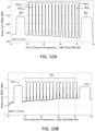
- FIG. 10A illustrates a typical time-averaged optical spectrum at an input of an OA 520 in the outbound OF line 581.
- FIG. 10B illustrates a time-averaged optical spectrum at an input of an OA 540 in the return OF line 582 in some embodiments, as described below.
- the optical frequency axes show the C-band ITU channel number, which is the offset from 190 THz in units of 100 GHz.
- the probe channels 931 are examples of the probe channels C n described above. They are centered close to every second ITUC channel from ITUC51 to ITUC21, i.e. with the probe channel spacing ⁇ v ⁇ 200GHz.
- the center frequencies v n of the probe channels 931 in FIGs. 10A and 10B are indexed in an ascending order from v 1 to v 16 .
- the shown spectrum correspond to a measurement by an optical spectrum analyzer (OSA) with a resolution bandwidth (RBW) that exceeds the bandwidth of an probe channel C n , which may be e.g. about 80 MHz, but is smaller than the probe channel spacing and the bandwidth of each of the load channels, i.e. approximately 3.75 GHz in this example.
- the time averaged power of a channel can be calculated as the height of the corresponding channel peak, converted to power with unit mW, and multiplied by the RBW.
- At least the first ( N -1) of the OLB paths 570 n are wavelength-selective, to select substantially only back-scattered light of the corresponding n-th probe channel C n (e.g. one of the probe channels 931, FIG. 10A ) to cross from the sensing OF line 581 into the return OF line 582, while substantially rejecting, or filtering out, the reminder of the back-scattered light 531 n .
- the part 532 n of the back-scattered light 531 n from the n-th OFS 530 n that is being cross-coupled into the return OF line 582 comprises predominantly the back-scattered light of the n -th probe channel C n .
- each of the N OFS 530 n is interrogated using a corresponding probe channel C n , with different probe channels C n used to interrogate different ones of the OFSs 530 n .
- the optical filter 578 may be omitted, or may be configured to pass therethrough only one, or a subset of, the probe channels C n and the load light, e.g. only the probe channel C N and the load light, to propagate to the OAs 540 of the return OF line 582.
- the de-couplers 573 may have different characteristics for light propagating along the optical fiber segment 530 n in the forward and return directions.
- the de-couplers 573 preferably allow all light propagating in the forward direction to pass therethrough, preferably with little or no attenuation, while re-directing ("dropping") at least part of the back-scattered light 531 n in the return direction along the corresponding OLB path 570 n .
- the de-couplers 573 may be embodied, for example, with backward-oriented directional couplers or, preferably, optical circulators.
- a de-coupler 573 at an input of the n-th OFS 530 n may be wavelength-selective to predominantly re-direct, i.e. drop, the back-scattered light of the corresponding probe channel C n (wavelengths ⁇ n ).
- the add-couplers 577 n may be wavelength-multiplexing to selectively add the back-scattered light of the corresponding probe channels C n (wavelengths ⁇ n ) to the return light propagating back toward the apparatus 510 along the return OF line 582.
- the add-couplers 577 n may be configured to selectively block light of the probe channel C n at wavelength ⁇ n , and to pass through toward the apparatus 510 the remaining ( N -1) probe channels at the wavelengths ⁇ m ⁇ ⁇ n , or at least all of the probe channels C m with m>n that are coupled into the return OF line 582 upstream of the add-multiplexer 577 n .
- the cross-coupled light signals 532 n , 532 n +1 , ..., 532 N of the probe channels C n , C n +1 , ..., C N propagate toward the input port 515 of the interrogating apparatus 510.
- FIGs. 6A-6D illustrate example wavelength-selective implementations of an add-coupler 577n.
- the add-coupler 577n includes a directional coupler 613 connecting to a fiber Bragg grating (FBG) 611 followed by an optical isolator 617 located in the return path upstream of the coupler 613.
- the FBG 611 is configured to selectively reflect light of the n -th probe channel C n (wavelength ⁇ n ) to propagate downstream the return path toward the apparatus 510, and to pass therethrough the remaining ( N -1) probe channels C m at the wavelengths ⁇ m ⁇ ⁇ n .
- the directional coupler 613 and the FBG 611 cooperate to act as a selective add-drop coupler for the n-th wavelength channel C n , selectively substituting light of the n-th probe channel C n received from the optical fiber segment 530 n via OLB 570 n for any light of the n-th channel C n that may be incident upon the FBG 611 in the downstream direction along the optical fiber segment 560 n .
- the optical isolator 617 may be omitted, at a potential expense of added noise on the sensing measurements due to sideband reflection from FBG 611 of not-selected channels C m , m ⁇ n or Rayleigh scattering of same channels upstream in the return OF line 582.
- the directional coupler 613 may have an asymmetric coupling ratio, so that more than 50% of light in the return path propagates through the coupler toward the input 515 of the apparatus 510, and less than 50% of the light entering in the direction from the de-coupler 573 is coupled to propagate upstream the return path.
- a 80/20 coupler may be used.
- the asymmetric coupling ratio of the coupler 613 reduces the transmission loss between two subsequent return-path OAs 540, at the expense of a somewhat higher gain of the optical preamplifier 575 in the optical loop-back path 570n. In this way the output power of the return-path OAs 540 can be reduced compared to an embodiment with a symmetric 50:50 coupler 513, thus reducing the nonlinear distortion in the return-path optical fiber segments 560 n .
- FIG. 6B illustrates an embodiment where the coupler 613 is replaced by a circulator 615.
- FIG. 6C illustrates an implementation of the add- coupler 577n, in which the FBG 611 is replaced with a thin-film filter (TFF) 622 having a passband that is smaller than the IF channel spacing ⁇ v and is centered at the wavelength ⁇ n .
- the TFF 622 is configured to selectively pass towards the interrogation apparatus 510 light of the probe channel C n received from the corresponding de-coupler 573, and light of the probe channels C n , m > n (wavelength ⁇ n+1 , ..., ⁇ N ) received from an upstream OA 540 in the return path.
- An advantage of this configuration compared to that of FIG. 6A is a potentially reduced insertion loss.
- a potential disadvantage is a possibly poorer extinction, i.e. the suppression of the dropped wavelengths relative to the transmitted, which may lead to a crosstalk between sensing signals from different optical fiber spans 530.
- FIG. 6D illustrates an implementation of the add-coupler 577 n combining the FBG 611 with the TFF 622. This implementation may be useful if the FBG 611 has poor sidelobe suppression in reflection.
- the TFF 622 may improve the extinction of not-selected channels C m , m ⁇ n, in the optical loopback path 570 n downstream of the optical preamplifier 575.
- the optical power of the back-scattered light 532 n at the optical input 515 of the apparatus 510 should be sufficiently above noise, e.g. sufficiently above the shot noise limit and above the amplified spontaneous emission (ASE) generated by the OAs 520, 575, and 540 along the corresponding optical path.
- the level of non-linear distortions of the interrogation signal 501 along the OF line 581 should be sufficiently low to enable the extraction of useful sensing information at the apparatus 510.
- the OFSs 530 n function both as distributed optical sensing elements and optical relay elements to relay the interrogation light along the outbound OF line 581.
- the accumulation of nonlinear distortions along the OF line 581 by the interrogation light 501 may complicate the sensing along those of the OFSs 530 n that are at the far end of the OF line 581.
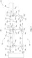
- FIG. 7 illustrates an example DOFS system 700 ("system 700") according to another embodiment.
- the DOFS system 700 illustrated in FIG. 7 is a modification of the DOFS system 500 and includes many of the same elements; elements that are common for the systems 500 and 700 are indicated in FIGs. 5 and 7 with same reference numerals and may not be further described.
- the system 700 differs from the system 500 by using different optical fibers for relaying the interrogation light 501 therealong (optical fibers 730 n ) and for optical sensing (optical fibers 740 n ).
- the system 700 includes the interrogating apparatus 510 that connects to an OF system 780, e.g. as described above with reference to the apparatus 510 and the OF system 580.
- Each, or at least some, of the optical segments 750. includes a relay optical fiber 730 n and a sensor optical fiber 740 n .
- the first, or input, ends of both the relay optical fiber 730 n and the sensor optical fiber 740 n are optically connected to a previous one of the optical segments 750 of the sequence, 750 n-1 , or to an output 511 of the apparatus 510 for the first segment 750 1 .
- a second, or output, end of the relay optical fiber 730 n is optically connected to an input of a subsequent one, i.e. 750 n+1 , of the optical segments 750 of the sequence.
- the last segment 750 N may include only a sensor optical fiber 740 N connected to the second end of the relay optical fiber 730 N -1 of the preceding optical segment 750 N-1 via the last OA 520 in the sequence.
- the length of one segment 750 may be e.g.
- the length of the relay and sensor optical fibers of a same segment 750 may be about the same. In some embodiments, the length of the relay and sensor optical fibers of a same segment 750 may differ; e.g. they may not be located along each other. Some embodiments may include segments 750, e.g. those that are sufficiently short, where the relay optical fiber of the segment also serves as the sensor optical fiber of the segment, as described above with reference to FIG. 5 .
- the OF line 781 is configured to amplify light propagating therethrough.
- the amplification is provided by the OAs 520, each embodied as a rare-earth doped OF A, such as an EDFA.
- the OAs 520 may use Raman amplification in an optical fiber contained therein.
- distributed Raman amplification along the relay optical fibers 730 n may be used; for such embodiments, the OAs 520 shown in FIG. 7 may symbolically represent such distributed Raman amplification in a corresponding relay optical fiber 730.
- the OAs 520 are disposed to amplify the interrogation light 501 prior to launching thereof into both the relay optical fiber 730 n and the sensor optical fiber 740 n of the subsequent optical segment 750 n , e.g. using an optical splitter 772.
- a selected part 742 n of light 741 n that is back-scattered and/or back-reflected at different locations along the sensor optical fiber 740 n is cross-coupled into the return OF line 582 by an OLB path 770 n .
- the selected part 742 n may be light of the n -th probe channel C n .
- an OLB path 770 n may include an optical circulator 774, an optional optical preamplifier 522, and a wavelength-selective add-coupler 577 n .
- the wavelength-selective add-coupler 577 n may be embodied, e.g., as described above with reference to FIG. 5 , and FIGs. 6A-6D .
- the optical circulator 774 is one embodiment of the de-coupler 573 described above, and may be replaced with a directional optical coupler, at a cost of a higher loss.
- the optical splitter 772 may have an asymmetric optical splitting ratio to direct relatively more light into the sensor optical fiber 740n than the relay optical fiber 730 n .
- nonlinear distortions of the interrogating light 501 in the OF line 781 may be controlled to an acceptable level, while at the same time sending enough light into the sensor optical fiber 740 n to obtain therefrom a sufficient amount of back-reflected light 742 n of the n -th probe channel C n .
- An optimal value of the splitting ratio of the optical splitter 772 may depend on a particular implementation, e.g. on the length of the relay and sensor optical fibers 730 n , 740 n , on the fiber type, etc.
- the optical splitter 772 may be configured to couple into the sensor optical fiber 740 n at least 3 times, or at least 4 times, or preferably at least 5 times more optical power than into the relay optical fiber 730 n .
- the optical splitter 772 has a splitting ratio of 15:85.
- the optical splitter 772 may be configured to direct at least as much, or more, optical power into the relay optical fiber 730 n than the sensor optical fiber 740 n .
- the fraction of probe light directed into the sensor optical fiber 740 n may be selectively amplified by a booster OA (not shown) connected between the optical splitter 772 and the sensor optical fiber 740 n .
- the interrogating apparatus 510 of any of the systems 500 and 700 may be an embodiment of the apparatus 100 or the apparatus 300 described above that is configured to transmit within a transmission period T 803, K optical probe signals at a temporal series 801 of K corresponding (pulse) start times t 1 , t 2 , ..., t k , ... t K ("start times t k "), so that different ones of the optical probe signals within the transmission period T are transmitted in different wavelength channels having different center wavelengths ⁇ k , e.g. different ones of the wavelength channels C n , e.g. such as the wavelength channels 931 n of FIGs. 10A and 10B .
- start times t k start times
- each of the probe signals 815 may be a single optical pulse or a sequence of optical pulses, together spanning a frequency band of a spectral width B c that is much smaller than the frequency spacing ⁇ v between adjacent ones of the wavelength channels.
- the interrogating apparatus thus transmits, over a transmission period T 803, K optical probe signals 815 at K different center wavelengths ⁇ k , after which the transmission may be repeated with a repeat period T r ; in this way, at each center wavelength ⁇ k the interrogator transmits a periodic sequence of optical probe signals 815 with the repeat period T r ("sampling period") equal or greater than the transmission period T of the pulse sequence.
- T r ⁇ T K ⁇ ⁇ t, where ⁇ t is the time delay between consecutive start times, and is the transmission duration of one optical probe signal 815.
- the transmission duration t p 810 of one optical probe signal 815 is smaller than the time delay ⁇ t , so that optical probe signals 815 of different wavelength channels transmitted at consecutive start times, e.g. t k and t k +1 , do not overlap.
- optical probe signals 815 of different wavelength channels transmitted at consecutive start times may partially overlap in time, e.g. at edges thereof.
- the number K of the optical probe signals 815 transmitted over one transmission period T 803, and thus the number of spectrally separate wavelength channels in which the optical probe signals are transmitted is equal to the number N of different optical fibers to be interrogated with the corresponding ones of the optical probe signals 815.
- the N sensor optical fibers 740 n of the optical system 780 may be interrogated by cycling through N wavelength channels C n , transmitting the optical probe signal 815 of each wavelength channel at a different one of the transmission start times t k .
- the optical transmitter e.g. of the interrogator apparatus 510, may repeatedly cycle through the N wavelength channels C n with a repeat period T r equal or greater than the transmission period 803 T .
- a same optical probe signal 815 may be used to interrogate two or more of the N sensor optical fibers 740 n of the optical system 780, so that the number K of the spectrally separate wavelength channels is smaller than N.
- the repeat period T r may be suitably extended to avoid temporal overlaps at the receiver of light of a same optical probe signal back-scattered in different optical fibers.
- the center wavelength of the optical probe signals 815 with successive start times t k increases step-wise over the duration of the transmission period 803.
- the center wavelength decreases step-wise over the duration of the transmission period 803.
- Such transmission scheme results in a relatively large wavelength shift of about ( N -1) ⁇ at a juncture of consecutive transmission periods 803.
- an abrupt large wavelengths shift of probe light may cause undesired transient response of the OAs of the optical fiber line being interrogated, e.g. the OAs 520 of FIGs. 5 or 7 . It may therefore be preferable to limit wavelength shifts between consecutive probe signals 815 to values that are much smaller than the OA gain bandwidth, e.g. less that 1 ⁇ 4 thereof.
- "abrupt” refers to changes that happen on a time scale comparable or faster than a gain relaxation time in the downstream OAs 520.
- the gain relaxation time for an EDFA may typically be in 5 - 10 ⁇ s.
- the center wavelength of the optical probe signals 815 first increases, e.g. over approximately one half of the transmission period 803, and then decreases, e.g. over the other half of the transmission period 803.
- the center wavelength first decreases, and then increases over the duration of the transmission period 803.
- Such a scheme has a potential advantage of limiting abrupt wavelength shifts of the probe light both within and between the transmission period 803.
- a similar scheme that may also provide sufficient advantage by limiting abrupt wavelength shifts is one where the center wavelength of the transmission increases over 1 ⁇ 4 of the transmission period then decreases over another 1 ⁇ 4 of the same transmission period, then increases over another 1 ⁇ 4 of the same transmission period, and finally increases over the last 1 ⁇ 4 of the same transmission period,.
- the center wavelength of the transmission increases by stepping up through the "even" wavelength channels with the central wavelengths ⁇ 2k over about half of the transmission period T 803, and then, the center wavelength of the transmission decreases by stepping down through the "odd" wavelength channels with the central wavelengths ⁇ 2k+1 over the other half of the transmission period T 803, e.g. not exceed about 2 ⁇ .
- Both embodiments, with small wavelength changes between steps, are expected to result in a more stable operation of the downstream OAs, e.g. the OAs 520 of FIGs. 5 and 7 .
- FIG. 9A illustrates an example optical pulse sequence 900 of a probe light that may be generated by optical transmitter(s) of an OFI, such as e.g. the optical transmitter 130 or the optical transmitters of the OFI 340 or the interrogator apparatus 510, for interrogating sixteen optical fibers of an optical fiber line.
- the optical pulse sequence 900 is transmitted over a transmission period T 910 at a temporal series of 16 start times spaced by a same time delay 901.
- Each consecutive pulse 903 has a different center wavelength than the preceding pulse, so that different pulses 903 of the sequence 900 are transmitted at different center wavelengths (different wavelength channels C n ).
- each of the pulses 903 is labeled with a corresponding center wavelength thereof ⁇ 1, ⁇ 2, ..., ⁇ 16, with the center wavelengths here being numbered in a wavelength-increasing order, so that ⁇ 1 ⁇ ⁇ 2 ⁇ ⁇ 3 ⁇ ... ⁇ ⁇ 16.
- the probe light e.g. 331
- the consecutive pulses 903 do not overlap in time, which eliminates or at least reduces nonlinear distortion of the pulses due to the four-wave mixing (FWM) in the optical fiber line being interrogated. Accordingly, both the wavelength and the optical power of the probe light varies in time, with the transmission wavelength abruptly changing and the optical power dropping at transitions between consecutive ones of the pulses 903.
- FWM four-wave mixing
- the optical amplifiers thereof may react to the changes in the input optical power and/or wavelength by varying the amplifier gain, causing undesired transients, e.g. spikes and/or ripples, in the optical probe pulses at the amplifier output(s). These transients may grow in amplitude as the probe pulses propagate through a series of optical amplifiers, e.g. the OAs 520 of FIGs. 5 and 7 .
- the downstream optical amplifiers are rare-earth doped OF As, e.g. EDFAs.
- the gain spectrum of an active medium (e.g. erbium-doped fiber) of an OFA is typically broad but varies significantly with wavelength on a scale of a few nanometers.
- Such optical amplifiers typically include gain flattening filters (GFFs) to flatten a net gain spectrum of the optical amplifier over a target wavelength range, changes in the wavelength or power of the light being amplified may change the net gain experienced by the light being transmitted through the amplifier.
- GFFs gain flattening filters
- the gain of the downstream optical amplifiers, and the amplification of the probe pulses 903 therein, may be at least partially stabilized using the load channels 113, 123 spectrally located at both the short-wavelength side and long-wavelength side of the optical probe signal, e.g. as described above with reference to FIGs. 1 and 2 , and by temporally varying the optical power of the load light at both sides of the probe signal spectrum so as to counteract changes in the optical probe signal.
- the center wavelength of the pulses 903 first increases, and then decreases over the duration of the transmission period 910 ( ⁇ 600 ⁇ s in this example); this limits the maximum wavelength shift at signal transitions.
- the overall wavelength variation of the probe light across the optical pulse sequence 900 may still have a significant effect on the OA gain spectrum.
- Some embodiments may therefore use one or more channels of temporally varying load light in addition to the probe light to stabilize the gain of optical amplifiers in an optical fiber line being interrogated.
- the gain of the downstream optical amplifiers, and the amplification of the probe pulses 903 therein may be at least partially stabilized using load channels spectrally located at both the short-wavelength side and long-wavelength side of the optical probe signal, e.g. as described above with reference to FIGs. 1 and 2 , and by temporally varying the optical power of the load light at both sides of the probe signal spectrum so as to counteract changes in the optical probe signal.
- FIG. 9B illustrates, for an example embodiment described above with reference to FIG. 9A and below with reference to FIGs. 10A, and 10B , the modulation of load light in load light channels 911 and 921 synchronized to the pulse sequence 900 of FIG. 7A.
- the load light channels 911 and 921 are spectrally located at opposite sides of the entire spectrum of the probe channels 931, as illustrated in FIGs. 10A and 10B .
- the load light channels 911 and 921 are examples of the load light channels 113, 123 described above with reference to FIGs. 1 and 2 .
- the horizontal (time) axes in FIGs. 9A and 9B are aligned to illustrate temporal variations happening synchronously in the probe channels ( FIG. 9A ) and the load channels ( FIG. 9B ).
- the load light of the load channels 911, 921 is injected into an optical fiber line, e.g. 581 or 781, together with the probe pulse sequence 900 to stabilize the gain of downstream optical amplifiers, e.g. OAs 540 ( FIGs. 5 and 7 ).
- an optical fiber line e.g. 581 or 781
- the probe pulse sequence 900 to stabilize the gain of downstream optical amplifiers, e.g. OAs 540 ( FIGs. 5 and 7 ).
- the spectrum shown in FIG. 10A is a typical time-averaged spectrum of the interrogation light 501 at an input to, e.g., one of the optical relay fibers 730 n .
- FIG. 9B shows a typical time-averaged spectrum at an input to one of optical fiber segments 560 n , i.e. the output one of the OAs 540 in the ROF line 582, for an example configuration of the OLB path 570 N or 770 N described below.
- Spectral lines 931 1 , 931 2 , ..., 931 N represent the spectrum of the probe pulse sequence 900 of FIG. 9A ; they correspond to the sixteen wavelength channels C n of the probe light, with the respective central frequencies v 1 , v 2 , ... , v 16 (wavelengths ⁇ 1 , ⁇ 2 , ... , ⁇ 16 in FIG. 9A ), and may be referred to as the wavelength channels 931 of the probe light, or the probe channels 931.
- the wavelength channels 931 of the probe light are approximately aligned with the C-band ITU frequency grid, and are spaced by approximately 200GHz.
- the frequency spacing of the probe channels C n may be somewhat uneven to reduce four-wave mixing.
- Load light in a second load channel 921 includes wavelengths that are greater than any of the wavelengths of the probe channels 931 1 , 931 2 , ..., 931 N .
- the spectral width of each load channel 911 and 921 preferably exceeds the spacing ⁇ between adjacent ones of the central wavelengths ⁇ n of the probe channels 931, which tends to reduce the spectral density of random intensity fluctuations in bandwidth-limited white light load signals.
- the large spectral width of the load channels 911, 921 may be advantageous for reducing XPM and XPolM of the optical probe signals by variations of the load light power, both in the outbound OF line 581, 781 and the return OF line 582, 782.
- the spectral width of each load light channel 911, 921 exceeds 2 ⁇ .
- one of the load channels 911 and 921 e.g. the short-wavelength load channel 911
- the other of the load channels 911 and 921 e.g. the long-wavelength load channel 921
- the active optical fiber may be e.g.
- the operating bandwidth is a spectral bandwidth that comprises all channels of the probe light and the load light channels.
- the spectral profile of the active fiber gain spanning the operating bandwidth may be measured, e.g., using a source of white light, with a same input optical power and a same pump power as expected during normal operation of the OFA(s).
- the figure shows temporal variations of the load light power in the short-wavelength load channel 911 (solid line) and in the long-wavelength load channel 921 (dashed line).
- the load light of the load channels 911, 921 is injected into an optical fiber line, e.g. the OF line 581 of FIG. 5 or 781 of FIG. 7 , together with the optical pulse sequence 900 to stabilize the gain of downstream optical amplifiers, e.g. OAs 520 ( FIGs. 5 , 7 ).
- the optical power in the load light channels 911, 921 varies in time in synchronization with the pulse sequence 900 of FIG. 9A , to counteract the effect of probe light power and wavelength variations during the pulse sequence 900 in FIG. 9A on downstream optical amplifiers of the outbound optical fiber line, e.g. the OAs 520.
- the optical power of both the first (911) and second (921) load light channels briefly rises in-between consecutive probe pulses 903, so as to at least partially compensate the effect of a drop in the power of the probe light on the gain of the downstream optical amplifiers, e.g. the OAs 520 in FIGs. 5 , 7 .
- this is manifested by load light peaking 922 in-between the probe pulses 903, when the total optical power of the probe light drops.
- the load light peaking 922 at transitions between consecutive probe pulses may be absent, e.g. if the consecutive probe pulses overlap at the edges so that the drops in the optical power of the probe light at pulse-to-pulse transitions are absent or small.
- the optical powers of the two load channels 911 and 921 change in opposite directions after a change in the center wavelength ⁇ n of probe light transmission, e.g. in a middle portion of a subsequent pulse 903 after the peaking 922 (if present) at pulse to pulse transitions; changing the optical powers of the two load channels 911 and 921 in opposite directions responsive to a (step-wise) change in the transmission center wavelength ⁇ n may at least partially counteract the effect of changing the center wavelength ⁇ n of the probe light upon the gain spectrum G( ⁇ ) of the downstream OAs 520.
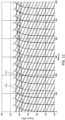
- FIG. 11 shows, for the example described above with reference to FIGs. 9A-10B , a typical evolution of optical power that is expected to be returned back to the apparatus 510 in different ones of the probe channels 931 due to the Raleigh back-scattering in, e.g., the sensor optical fibers 740 n .
- the Raleigh scattering is a random process, and the power of the scattered light will generally fluctuate, e.g. around the values plotted for the illustrated example.
- FIG. 11 shows the expectation values (mean values) of the optical power of the return light in each probe channel C n (spectral lines 931 in FIGs. 10A.
- actual signal power of the back-scattered light may fluctuate with a standard deviation that is comparable to the mean value (typically about one half thereof), and with a bandwidth equal to the optical bandwidth of the optical probe signal in the channel. These fluctuations may add some undesired SPM-induced phase noise into the response optical signal 585.
- the peak expectation value of the optical power of the back-scattered light in each probe channel at the output of a return-path OA 540 should be limited, e.g. preferably to about 0.3 mW or less in some typical embodiments.
- this corresponds to a time average per probe channel C n less than about (-12) dBm, or less than about 0 (zero) dBm summed over all 16 probe channels 931 in this example.
- an EDFA operating with an output power of less than 0 dBm will operate in an unsaturated regime where the gain has little dependence on the input optical power. This may be especially the case when the pump power is high, which may be desirable in order to achieve a low noise figure operation. It may be advantageous to operate the return-path OAs 540 in the saturated regime, since this will tend to stabilize the optical power of the return light as it propagates. In some implementations, operation of the return-path OAs 540 in the saturated regime may be achieved, e.g., by increasing the light power in at least one of the load channels 911, 921, or in a different load channel that may be unmodulated.
- the OF system 580 or 780 is configured to have a higher ratio between the load light power and the probe signal power in the return OF line 582 than in the outbound OF line 581 or 781; see e.g. FIGs. 10A and 10B , where the ratio of the optical power in the probe channels 931 to the optical power in the load channels 911, 921 is different.
- Such operation may be achieved, e.g., using the filter 578, which may have different, e.g. greater, attenuation for the probe channels than the load channels.
- the mean power of each probe channel 931 at the output from the first return-path OA 540 of the ROF line 582 is about -12 dBm, as suggested above, while the load channels 911, 921 carry about 7 dBm each.
- the mean power of each probe channel is greater, i.e. about -5.1 dBm, while the load channels 911, 921 are lower in power, about 0.5 dBm each ( FIG. 9A ).
- the last, i.e. N -th, OLB path e.g. 570 N or 770 N
- the last, i.e. N -th, OLB path e.g. 570 N or 770 N
- light of the load channels e.g. 911 and 921
- the sensing optical fibers e.g. 530 n or 740 n
- the Rayleigh back-scattered load light has intensity noise distributed over the bandwidths of the respective load channels 911, 921.
- This intensity noise of the back-scattered load light may cause phase and polarization noise on the back-scattered light in the probe channels 731 through XPM and XPolM.
- the group delay dispersion may cause some of this noisy modulation to be averaged out, since the load light and the optical probe signals travel at different speeds through the ROF line 582. Signal in the probe channels that are spectrally close to the load channels may still be affected.
- the degradation of the back-reflected optical probe signals in the return OF line 582 e.g. the back-reflected light of the optical probe signals 815 or 903 ( FIGs.
- due to the cross-modulation with the noisy load light may be reduced by increasing the load channel bandwidth to be much greater than the probe signal bandwidth B c , preferably to be greater than the probe channel spacing ⁇ v, thus spreading much of the cross-modulation intensity noise to frequencies that are outside of the detection bandwidth used in the optical receiver of the interrogating apparatus.
- the probe signal full-width-half-maximum bandwidth was 80 MHz we have observed no measurable degradation with the 500 to 600 GHz load bandwidth shown in FIGs. 9A and 9B .
- one or more of the OLB paths 770 n may be configured to cause light of one or more of the load channels to bypass one or more of the sensor optical fibers 740 n , and to enter the return OF line 532. This may avoid the XPM and/or XPolM of the probe channel signals in the ROF line 582 by the Raleigh back-scattering induced intensity noise of the load light.
- the bandwidth of the load channels that bypass the sensor optical fibers 740 n may be smaller, e.g. less than the probe channel spacing, thereby reducing requirements to the total OA bandwidth.
- the load light spectrum may be broadened to suppress stimulated Brillouin scattering, e.g., by applying phase modulation with a moderate bandwidth (typically between 50 and 1000 MHz).
- the load channel(s) that stabilize(s) the gain of the OAs of the outbound OF line 781 may be different from the load channel(s) that stabilize(s) the gain of the OAs in the return OF line 582, and may lack intensity modulation by the OFI.
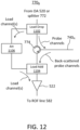
- load light is separated from the probe pulses in the last OLB path 570 _N or 770 N with a wavelength-selective drop filter 1102 located upstream of the circulator 774 (or the last de-coupler 573 of the OF line 531 of FIG, 5 ) to bypass the sensor optical fiber 740 N , and rejoined with the back-reflected probe signals by a wavelength-selective add filter 1104, preferably before the input to the optical preamplifier 552.
- the load light bypassing the circulator 774 may be suitably attenuated with an optical attenuator 1106.
- light of the corresponding load channels may be separated from the probe pulses and, possibly, from other modulated load light, to bypass the last de-coupler 573 and the optical fiber segment 530 N of the OF line 531 of FIG. 5 to enter the OLB path 570 N .
- the OLB path 770 N or 570 N may be configured to selectively block light of one or more load channels to prevent said light from entering the ROF line 582., e.g. using wavelength filtering somewhere along the OLB path 770 N or at the output of the nearest upstream OA 520.
- the load channel(s) being blocked may include, e.g. those of the load channels that are modulated to stabilize the gain of the OAs 520 of the OOF line 781.
- an OFI e.g. the OFI 340
- may be configured to output a temporally ordered set of optical probe pulses of different wavelength channels (channel center wavelengths ⁇ n , channel frequencies v n c/_ ⁇ n ), wherein consecutive probe pulses of the sequence temporally overlap at the edges.
- consecutive refers to two pulses with consecutive transmission start times, (smallest non-zero time delay).
- the duration of the rising and falling edges of the probe pulse (“on/off transition times") may be relatively small, so as to reduce the overlaps between probe pulses of different wavelengths and thus to lessen the FWM.
- the on/off transition times of a probe pulse may each be less than about 2 ⁇ sec, or preferably less than about 0.2 ⁇ sec.
- Very short apodization times may lead to the appearance of undesired side-lobes in the compressed signal at the output of the matched-filter processing.
- the OFI may be configured to correspondingly apodize the matched-filter impulse response used for the chirp compression, and/or to increase a chirp rate at the start and the end of the pulse, as described above with reference to FIG. 4 . These measures may lessen the magnitude of the undesired side-lobes.
- the optical probe pulses 1201 of different wavelength channels may be time-ordered such that the wavelength change at pulse-to-pulse transitions is minimized; this can for instance be achieved by ordering the channel frequencies v n of consecutive pulses 1201 to monotonically step in a same direction, e.g. from high to low or from low to high, throughout the pulse sequence. Such ordering may reduce OA-induced distortions of the pulse shape for most of the probe pulses as they propagate in the OF line being interrogated (e.g. the OF line 581 or 781), as reducing a wavelength change of input light tend to reduce changes in the steady-state spectral gain profile in the active (rare-earth doped) optical fibers of the OAs 520.
- Some OA gain instability may however occur when stepping from the end of one such pulse sequence to the start of the next pulse sequence. In some implementations, this may be mitigated, e.g., by adding some "idle" time between consecutive ones of the pulse sequences when no probe light is transmitted, e.g. as illustrated at 807 in FIG. 8A , and transmitting during this idle time, e.g. 807, a corresponding amount of optical power in a load light channel. This load light channel may be spectrally close to, but still separate from, the wavelength channel of the first probe pulse in the sequence.
- the OFI may be configured to step through, e.g., the odd numbered probe channels in sequence for a first half of the pulse sequence, followed by the even numbered probe channels in the opposite direction, as it illustrated in FIG. 8B .
- the channels are assumed to be numbered sequentially in the direction of increasing channel wavelength or channel frequency.
- DOFS systems can also be used in optical systems that differ in some aspects from the ones described above.
- Such other DOFS systems include, for instance, various distributed sensing systems that use pulsed or intensity modulated interrogation light to interrogate optical fibers, such as but not limited to Raman DTS systems, distributed Brillouin sensing systems, pulsed OTDR systems, pulsed interferometer interrogation systems, pulsed FBG interrogation systems.
- all of the above DOFS systems may be configured to use amplified multi-segment relay optical lines with separate sensor optical fibers coupled to at least some of the relay fiber segments.
- DOFS systems may be used in long-haul submarine telecom systems.
- DAS can be added for submarine telecom cable threat monitoring by dedicating a separate fiber pair for DAS to establish a surveillance system that generates early warnings if a potential threat is detected in the vicinity of the submarine telecom cable.
- Dedicated submarine DAS sensing cables may also be installed alongside, or piggybacked to electricity power cables, or seabed hydrocarbon carrying pipelines, for, e.g., detection and localization of leaks or electrical faults, and/or for cable or pipeline threat monitoring.
- the DAS sensing capabilities of such a system can also contribute to the SMART cables initiative where environmental sensing in introduced to submarine telecom systems for oceanographic and climate research objectives. In this respect, DAS can contribute with oceanographic observations on mammals, earthquakes, tsunamis, temperature or strain fluctuations etc.
- the apparatus comprises: an optical interrogator (e.g. 100, 300, 510) for distributed optical fiber sensing comprising an optical transmitter (e.g. 130), an optical receiver (e.g. 140), and first and second load light sources (e.g. 110, 120; 310, 320).
- the load light sources are connected to transmit temporally varying load light to an optical output (e.g. 101, 301, 511) of the optical interrogator.
- the optical transmitter e.g. 130
- optical probe signals e.g. 131, 331, 401, 815, 903
- the temporally varying load light from the first load light source occupies a wavelength range (e.g. 113; 911) on an opposite side of a wavelength range (e.g. 133; 931) of the optical probe light as the temporally varying load light from the second load light source (e.g. 120, wavelength range 123 or 921).
- Wavelengths of the temporally varying load light are in an amplification range for rare-earth doped amplifiers.
- the optical transmitter (e.g. 130) is configured to transmit the optical probe signals at a temporal series (e.g. 801) of start times t k , such that the optical probe signals (e.g. 815, 903) transmitted at different start times of the temporal series have different center wavelengths.
- the center wavelengths of the optical probe signals (e.g. 815, 903) transmitted at different ones of the start times have a spectral spacing, the spectral spacing being smaller than a spectral bandwidth of the temporally varying load light from either of the load light sources.
- the optical probe signals (e.g. 815, 903) having different center wavelengths do not overlap in time.
- the optical probe signals (e.g. 815, 903) having different center wavelengths partially overlap in time.
- At least one of the load light sources may be configured to output the load light therefrom with intensity peaks (e.g. 922) between consecutive ones of the optical probe signals (e.g. 903).
- the optical interrogator is such that intensities of the load light output by the first and second load light sources are changed in opposite directions by a change to a different one of the center wavelengths during transmission of the optical probe signals.
- any of the above implementations may further comprise an optical fiber line (e.g. 163, 581, 781) having a series of optical fiber segments (e.g. 530, 730) connected to the output of the optical interrogator, the optical fiber segments being end-connected by optical amplifiers (e.g. 165, 520).
- optical amplifiers e.g. 165, 520
- at least some of the optical amplifiers may be rare-earth doped optical fiber amplifiers.
- the optical receiver e.g. 140
- any of the above implementations may further comprise a return optical fiber line (e.g. 582, FIGs. 5 and 7 ) optically connected to return light back scattered by the optical fiber segments to the optical receiver, the return optical fiber line comprising a sequence of optical fibers (e.g. 560) end connected by rare-earth doped optical amplifiers (e.g. 540).
- a return optical fiber line e.g. 582, FIGs. 5 and 7
- the return optical fiber line comprising a sequence of optical fibers (e.g. 560) end connected by rare-earth doped optical amplifiers (e.g. 540).
- the bandwidth of load light (e.g. 111, 121) output by each load light source (e.g. 110, 120) may be larger than the bandwidth of individual ones of the optical probe signals (e.g. 131).
- each of the load light sources may include a bandpass filtered white light source (e.g. 307).
- the optical interrogator may be configured for distributed acoustic sensing along a plurality of optical fibers (e.g. 530; 740).
- some embodiments may include more than two load channels with temporally varying load light; e.g. a third load channel may be added spectrally between the first and second load channels to define two separate wavelength ranges for the OFI signal channels.
- Some embodiments may include only one load channel.
- other optical couplers may be used instead of circulators 774 to extract back-reflected light from optical fibers in the example OF system described above.
- a circulator may be used instead of a directional optical coupler in the add-couplers 577.
- Either multi-stage or single-stage optical amplifiers may be used for the OAs 165, 520, 575, 540.
- one or more of the OAs 165, 520, 575, 540 may be implemented using Raman amplification in the optical fibers 530, 730, 560 of the outbound and return OF lines, or using discrete Raman amplifiers where the amplifying fiber is contained within the amplifier unit, or with SOAs.
- one or more of the OAs 165, 520, 575, 540 may be implemented using semiconductor amplifiers (SA). Extra amplifiers may be added in certain paths, for instance in the path between the output of a return-path OA 540 and a downstream add-coupler 577.
- SA semiconductor amplifiers
- one or more optical splitters 772 may branch out to multiple sensor fibers, potentially measuring different quantities and/or at different locations, where the backscatter of at least one channel from each sensor fiber is amplified and added into the ROF line 582.
- some of the splitters 772 may be a drop filter.
- some of the elements 573, 772, 577 may be grating-assisted add/drop couplers.
- figure numbers and/or figure reference labels in the claims is intended to identify one or more possible embodiments of the claimed subject matter in order to facilitate the interpretation of the claims. Such use is not to be construed as necessarily limiting the scope of those claims to the embodiments shown in the corresponding figures.
- Couple refers to any manner known in the art or later developed in which energy is allowed to be transferred between two or more elements, and the interposition of one or more additional elements is contemplated, although not required. Conversely, the terms “directly coupled,” “directly connected,” etc., imply the absence of such additional elements.
Landscapes
- Physics & Mathematics (AREA)
- General Physics & Mathematics (AREA)
- Optical Communication System (AREA)
Priority Applications (1)
| Application Number | Priority Date | Filing Date | Title |
|---|---|---|---|
| EP23306548.1A EP4528228A1 (fr) | 2023-09-19 | 2023-09-19 | Interrogateur pour détection à fibre optique distribuée avec sources de charge optique variables |
Applications Claiming Priority (1)
| Application Number | Priority Date | Filing Date | Title |
|---|---|---|---|
| EP23306548.1A EP4528228A1 (fr) | 2023-09-19 | 2023-09-19 | Interrogateur pour détection à fibre optique distribuée avec sources de charge optique variables |
Publications (1)
| Publication Number | Publication Date |
|---|---|
| EP4528228A1 true EP4528228A1 (fr) | 2025-03-26 |
Family
ID=88969632
Family Applications (1)
| Application Number | Title | Priority Date | Filing Date |
|---|---|---|---|
| EP23306548.1A Pending EP4528228A1 (fr) | 2023-09-19 | 2023-09-19 | Interrogateur pour détection à fibre optique distribuée avec sources de charge optique variables |
Country Status (1)
| Country | Link |
|---|---|
| EP (1) | EP4528228A1 (fr) |
Citations (7)
| Publication number | Priority date | Publication date | Assignee | Title |
|---|---|---|---|---|
| JPH09236513A (ja) * | 1996-02-29 | 1997-09-09 | Advantest Corp | コヒーレントotdr装置およびコヒーレントotdr測定方法 |
| US20080309925A1 (en) * | 2005-08-22 | 2008-12-18 | Tyco Telecommunications (Us) Inc. | System and Method for Monitoring an Optical Communication System |
| US20090214214A1 (en) * | 2004-06-25 | 2009-08-27 | Tyco Telecommunications (Us) Inc. | Optical Fiber Transmission System with Noise Loading |
| US20110194853A1 (en) * | 2008-10-21 | 2011-08-11 | Huawei Technologies Co., Ltd. | Method and device for monitoring submarine cable system |
| US20200036447A1 (en) * | 2018-07-25 | 2020-01-30 | Alcatel Submarine Networks | Monitoring equipment for an optical transport system |
| US20220397448A1 (en) * | 2021-06-15 | 2022-12-15 | Subcom, Llc | Extending dynamic acoustic sensing range and localization in undersea cables using loopbacks |
| EP4160941A1 (fr) | 2021-09-29 | 2023-04-05 | Alcatel Submarine Networks | Détection et surveillance distribuées utilisant des liaisons optiques amplifiées |
-
2023
- 2023-09-19 EP EP23306548.1A patent/EP4528228A1/fr active Pending
Patent Citations (7)
| Publication number | Priority date | Publication date | Assignee | Title |
|---|---|---|---|---|
| JPH09236513A (ja) * | 1996-02-29 | 1997-09-09 | Advantest Corp | コヒーレントotdr装置およびコヒーレントotdr測定方法 |
| US20090214214A1 (en) * | 2004-06-25 | 2009-08-27 | Tyco Telecommunications (Us) Inc. | Optical Fiber Transmission System with Noise Loading |
| US20080309925A1 (en) * | 2005-08-22 | 2008-12-18 | Tyco Telecommunications (Us) Inc. | System and Method for Monitoring an Optical Communication System |
| US20110194853A1 (en) * | 2008-10-21 | 2011-08-11 | Huawei Technologies Co., Ltd. | Method and device for monitoring submarine cable system |
| US20200036447A1 (en) * | 2018-07-25 | 2020-01-30 | Alcatel Submarine Networks | Monitoring equipment for an optical transport system |
| US20220397448A1 (en) * | 2021-06-15 | 2022-12-15 | Subcom, Llc | Extending dynamic acoustic sensing range and localization in undersea cables using loopbacks |
| EP4160941A1 (fr) | 2021-09-29 | 2023-04-05 | Alcatel Submarine Networks | Détection et surveillance distribuées utilisant des liaisons optiques amplifiées |
Similar Documents
| Publication | Publication Date | Title |
|---|---|---|
| Ip et al. | DAS over 1,007-km hybrid link with 10-Tb/s DP-16QAM co-propagation using frequency-diverse chirped pulses | |
| CN111181631B (zh) | 一种基于时分空分复用的有中继海底光缆扰动监测系统 | |
| EP2763330B1 (fr) | Système et procédé d'identification de défauts dans des systèmes de communication optique | |
| CN102100018B (zh) | 长中继器跨距的高损耗环回 | |
| KR101174223B1 (ko) | 광선로 감시 시스템 및 그 시스템에 포함되는 감시 장치 | |
| US6009220A (en) | Surveillance system for passive branched optical networks | |
| CN101159493B (zh) | 利用时分复用测试信号测试光放大链路 | |
| US6011623A (en) | Fault detection system for an amplified optical transmission system | |
| US7869708B2 (en) | COTDR arrangement with swept frequency pulse generator for an optical transmission system | |
| US9234790B2 (en) | Apparatus and methods utilizing optical sensors operating in the reflection mode | |
| JP3391341B2 (ja) | 光伝送路監視システム及びその監視装置及びその監視方法 | |
| US20230269019A1 (en) | Long distance distributed fiber optic sensing (dfos) and wdm communications over repeated fiber spans using all-raman amplification and coding schemes | |
| CN109556527B (zh) | 光纤应变测定装置和光纤应变测定方法 | |
| JP2002044019A (ja) | 放射電力等化器 | |
| JP2023527128A (ja) | マルチスパンファイバリンク上の分散型音響検知のための中継器設計 | |
| EP2685641A1 (fr) | Étage d'amplification optique pour surveillance otdr et procédé associé et système de surveillance otdr d'une liaison de communication optique | |
| EP4528230A1 (fr) | Das à répéteur avec filtres sélectifs | |
| EP4528228A1 (fr) | Interrogateur pour détection à fibre optique distribuée avec sources de charge optique variables | |
| EP4528229A1 (fr) | Interrogateur optique pour détection optique distribuée pour changer de manière régulière le canal de longueur d'onde de signaux de sonde optique dans le temps | |
| EP4528227A1 (fr) | Système de détection à fibre optique distribuée à segments multiples avec des segments ayant un capteur optique et des fibres de relais optique | |
| US12571673B2 (en) | Multi-span optical fiber das system with amplified-filtered loopback (AFLB) | |
| US20050196175A1 (en) | Method and apparatus for obtaining status information concerning an in-service optical transmission line | |
| US20060159464A1 (en) | Method and apparatus for in-service monitoring of a regional undersea optical transmission system using COTDR | |
| Yuksel et al. | Centralised optical monitoring of tree-structured passive optical networks using a Raman-assisted OTDR | |
| Gautheron et al. | COTDR performance optimization for amplified transmission systems |
Legal Events
| Date | Code | Title | Description |
|---|---|---|---|
| PUAI | Public reference made under article 153(3) epc to a published international application that has entered the european phase |
Free format text: ORIGINAL CODE: 0009012 |
|
| STAA | Information on the status of an ep patent application or granted ep patent |
Free format text: STATUS: THE APPLICATION HAS BEEN PUBLISHED |
|
| AK | Designated contracting states |
Kind code of ref document: A1 Designated state(s): AL AT BE BG CH CY CZ DE DK EE ES FI FR GB GR HR HU IE IS IT LI LT LU LV MC ME MK MT NL NO PL PT RO RS SE SI SK SM TR |
|
| STAA | Information on the status of an ep patent application or granted ep patent |
Free format text: STATUS: REQUEST FOR EXAMINATION WAS MADE |
|
| 17P | Request for examination filed |
Effective date: 20250917 |