EP4528236A1 - Appareil de mesure vibronique et procédé de traitement de signal dans un tel appareil de mesure - Google Patents
Appareil de mesure vibronique et procédé de traitement de signal dans un tel appareil de mesure Download PDFInfo
- Publication number
- EP4528236A1 EP4528236A1 EP24192348.1A EP24192348A EP4528236A1 EP 4528236 A1 EP4528236 A1 EP 4528236A1 EP 24192348 A EP24192348 A EP 24192348A EP 4528236 A1 EP4528236 A1 EP 4528236A1
- Authority
- EP
- European Patent Office
- Prior art keywords
- signal
- analysis unit
- unit
- measuring device
- sensor
- Prior art date
- Legal status (The legal status is an assumption and is not a legal conclusion. Google has not performed a legal analysis and makes no representation as to the accuracy of the status listed.)
- Withdrawn
Links
Images

Classifications
-
- G—PHYSICS
- G01—MEASURING; TESTING
- G01F—MEASURING VOLUME, VOLUME FLOW, MASS FLOW OR LIQUID LEVEL; METERING BY VOLUME
- G01F23/00—Indicating or measuring liquid level or level of fluent solid material, e.g. indicating in terms of volume or indicating by means of an alarm
- G01F23/22—Indicating or measuring liquid level or level of fluent solid material, e.g. indicating in terms of volume or indicating by means of an alarm by measuring physical variables, other than linear dimensions, pressure or weight, dependent on the level to be measured, e.g. by difference of heat transfer of steam or water
- G01F23/28—Indicating or measuring liquid level or level of fluent solid material, e.g. indicating in terms of volume or indicating by means of an alarm by measuring physical variables, other than linear dimensions, pressure or weight, dependent on the level to be measured, e.g. by difference of heat transfer of steam or water by measuring the variations of parameters of electromagnetic or acoustic waves applied directly to the liquid or fluent solid material
- G01F23/296—Acoustic waves
- G01F23/2966—Acoustic waves making use of acoustical resonance or standing waves
- G01F23/2967—Acoustic waves making use of acoustical resonance or standing waves for discrete levels
-
- G—PHYSICS
- G01—MEASURING; TESTING
- G01F—MEASURING VOLUME, VOLUME FLOW, MASS FLOW OR LIQUID LEVEL; METERING BY VOLUME
- G01F25/00—Testing or calibration of apparatus for measuring volume, volume flow or liquid level or for metering by volume
- G01F25/20—Testing or calibration of apparatus for measuring volume, volume flow or liquid level or for metering by volume of apparatus for measuring liquid level
- G01F25/24—Testing proper functioning of electronic circuits
-
- G—PHYSICS
- G01—MEASURING; TESTING
- G01F—MEASURING VOLUME, VOLUME FLOW, MASS FLOW OR LIQUID LEVEL; METERING BY VOLUME
- G01F23/00—Indicating or measuring liquid level or level of fluent solid material, e.g. indicating in terms of volume or indicating by means of an alarm
- G01F23/22—Indicating or measuring liquid level or level of fluent solid material, e.g. indicating in terms of volume or indicating by means of an alarm by measuring physical variables, other than linear dimensions, pressure or weight, dependent on the level to be measured, e.g. by difference of heat transfer of steam or water
- G01F23/28—Indicating or measuring liquid level or level of fluent solid material, e.g. indicating in terms of volume or indicating by means of an alarm by measuring physical variables, other than linear dimensions, pressure or weight, dependent on the level to be measured, e.g. by difference of heat transfer of steam or water by measuring the variations of parameters of electromagnetic or acoustic waves applied directly to the liquid or fluent solid material
- G01F23/296—Acoustic waves
- G01F23/2968—Transducers specially adapted for acoustic level indicators
-
- G—PHYSICS
- G01—MEASURING; TESTING
- G01F—MEASURING VOLUME, VOLUME FLOW, MASS FLOW OR LIQUID LEVEL; METERING BY VOLUME
- G01F23/00—Indicating or measuring liquid level or level of fluent solid material, e.g. indicating in terms of volume or indicating by means of an alarm
- G01F23/80—Arrangements for signal processing
- G01F23/802—Particular electronic circuits for digital processing equipment
- G01F23/804—Particular electronic circuits for digital processing equipment containing circuits handling parameters other than liquid level
-
- G—PHYSICS
- G01—MEASURING; TESTING
- G01F—MEASURING VOLUME, VOLUME FLOW, MASS FLOW OR LIQUID LEVEL; METERING BY VOLUME
- G01F25/00—Testing or calibration of apparatus for measuring volume, volume flow or liquid level or for metering by volume
- G01F25/20—Testing or calibration of apparatus for measuring volume, volume flow or liquid level or for metering by volume of apparatus for measuring liquid level
Definitions
- the present invention relates to a vibronic measuring device according to the preamble of patent claim 1 and to a method for signal processing in such a vibronic measuring device according to the preamble of patent claim 10.
- Vibration sensors also known as vibronic sensors or vibrating point level sensors, with piezoelectric transmitting and/or receiving devices are known from the state of the art. Piezoelectric transmitting and/or receiving devices are used as transmitting and/or receiving devices in vibration sensors, which are frequently used as point level sensors in level measurement technology. Such piezoelectric transmitting and/or receiving devices are often also referred to as drives.
- Vibration sensors in particular vibrating point level switches for liquids and bulk materials, operate according to the principle of resonant frequency shift and/or emit a vibration amplitude.
- the vibration sensor oscillates with a different resonant frequency and amplitude depending on the coverage level, density, and temperature of the medium.
- the amplitude of the resonant frequency depends on the viscosity of the medium.
- the frequency shift depends on the density and temperature of the medium.
- point level monitoring such sensors are mounted in containers at the height of a fill level to be monitored and output status information based on the above parameters. Specifically, information can be read from the sensors as to whether the sensor is covered or uncovered, or whether the fill level of the medium has reached (covered) or fallen below (uncovered) the fill level to be monitored.
- the vibration sensor has a membrane that can be excited to oscillate via such a drive, by means of which a mechanical oscillator arranged on the membrane can be excited to oscillate as a mechanical oscillating unit.
- a mechanical oscillator arranged on the membrane can be excited to oscillate as a mechanical oscillating unit.
- the mechanical oscillator oscillates with a characteristic Frequency that is detected by the vibration sensor and can be converted into a measurement signal.
- DE 10 2012 101 667 A1 relates to a vibronic measuring device for determining and/or monitoring at least one process variable of a medium in a container, comprising at least one mechanically oscillating unit, at least one piezoelectric drive and receiving unit for exciting the mechanically oscillating unit to mechanical vibrations by means of an electrical excitation signal and for receiving and converting mechanical vibrations into an electrical received signal, and at least one control and evaluation unit for controlling and/or regulating the vibration excitation and for evaluating the received signal with respect to the process variable.
- the process variable is, for example, the fill level, in particular a limit level, the density, the viscosity or the flow rate of a liquid medium, or the fill level of a bulk material.
- the control and evaluation unit according to the disclosure in DE 10 2012 101 667 A1 is configured to control the vibration excitation in the presence of at least one external vibration as a function of the frequency and/or the amplitude of the external vibration in such a way that the received signal is substantially undisturbed by the external vibration and/or to suppress at least one frequency of an external vibration in the received signal.
- the external vibration is detected on the aforementioned measuring device by interrupting the excitation of the mechanically oscillating unit to oscillate and evaluating the received signal during the interruption. This is considered disadvantageous because it prevents continuous measurement.
- the external vibration is detected by a vibration sensor arranged on the container, in or on the measuring device, or on a component connected to the container.
- the vibration sensor is preferably attached to the process connection of the measuring device.
- the second alternative represents an improved design, as it avoids interruptions in the measurement.
- the reliability However, the reliability and reliability of detecting extraneous vibrations with this system is still considered insufficient.
- the proposed solution of controlling the vibration excitation by changing the excitation frequency so that the received signal is essentially undisturbed by the external vibration is technically difficult to implement, since the resonance frequency of the mechanically vibrating unit depends on its geometry and the medium surrounding the unit and cannot be changed by changing the excitation.
- the excitation of higher vibration modes is possible, with external vibration at or near the resonance frequency of the main mode, the amplitude of these higher vibration modes is so small that signal evaluation is either impossible or inadequate in practice.
- a vibronic measuring device for determining and/or monitoring at least one process variable of a medium in a container, with at least one mechanically oscillatable unit, with at least one drive and receiving unit for exciting the mechanically oscillatable unit to mechanical oscillations by means of an electrical excitation signal and for receiving and converting mechanical oscillations into an electrical reception signal, has at least one control and evaluation unit for Regulation and/or control of the vibration excitation and for evaluating the received signal in relation to the process variable.
- the vibronic measuring device further comprises at least one vibration sensor which is coupled to the vibronic measuring device in such a way that vibrations are transmitted from the measuring device to the vibration sensor, wherein a sensor signal can be tapped at the vibration sensor.
- the vibronic measuring device comprises an analysis unit which is connected to the control and evaluation unit, wherein the electrical received signal and the sensor signal are fed to the analysis unit as input signals, the analysis unit is designed as a unit for the self-learning analysis of the input signals fed to it, and wherein the analysis unit transmits at least one item of reliability information for the electrical received signal to the control and evaluation unit.
- the vibronic measuring device is thus capable of analyzing the input signals supplied to it, in this case at least the received signal from the drive and receiving unit and the sensor signal from the vibration sensor, and of generating reliability information for the received signal in a self-learning manner.
- This reliability information can, in particular, contain a statement about whether and to what extent information about the process variable extracted from the received signal by the control and evaluation unit can be considered reliable.
- the vibronic measuring device is enabled to do this by the analysis unit, which is preferably designed as an AI unit trained using suitable training data.
- the AI unit can preferably be designed as an artificial neural network, to which various input data is fed depending on the embodiment of the present invention. Based on this input data, a statement about the reliability of the input data is determined.
- the artificial neural network can, for example, be designed as a multi-layer perceptron, i.e. feed forward neural network.
- Vibration sensors can be vibration sensors, acceleration sensors, and also inertial measurement units.
- An inertial measurement unit has three orthogonal acceleration sensors to detect the six possible kinematic degrees of freedom. (Translation sensors) for detecting the translational movement in the x-, y- and z-direction as well as three orthogonally aligned rotation rate sensors (gyroscopic sensors) for detecting rotational movements around the x-, y- and z-axis.
- Translation sensors for detecting the translational movement in the x-, y- and z-direction as well as three orthogonally aligned rotation rate sensors (gyroscopic sensors) for detecting rotational movements around the x-, y- and z-axis.
- Both the drive and receiver unit and the acceleration sensor are subjected to a superposition of vibrations resulting from the measurement itself—that is, the vibration induced by the drive unit in the mechanically vibrating unit—and external vibrations that, for example, couple to the vibronic measuring device via the container.
- the receiver unit "sees" this superposition through the mechanical filter of the mechanically vibrating unit and can therefore only detect the direction of the resulting vibration to a limited extent.
- the vibration sensor on the other hand, can record the vibration unfiltered and thus derive additional information.
- Preferred systems are those that can measure the direction, magnitude, and frequency of accelerations acting on the sensor, thus providing as much information as possible about potential external vibrations that could influence a measurement.
- the vibration sensor can be constructed, for example, as a three-axis accelerometer or a gyroscope using MEMS technology. The additional information about the direction and magnitude of the acceleration allows for better classification and evaluation of external vibrations.
- the analysis unit according to the present invention is designed such that the analysis of the input signals of the analysis unit takes place within the vibronic measuring device, thus eliminating the need for a connection to the cloud, i.e., in particular, a network connection.
- Further advantages of signal processing directly within the measuring device include, for example, shorter response times and easier data protection, since the raw data does not leave the measuring device.
- the conversion of signals from the time domain to the spectral domain is performed using spectral analysis.
- the Fourier transform, and in particular the Fast Fourier Transformation (FFT), has become established as a common algorithm for this purpose.
- Temperature has a significant influence on the natural frequency of the mechanically vibrating unit and can be determined without great effort. Many vibronic measuring devices therefore already have a temperature sensor or another type of temperature measurement, allowing the temperature to be used in further signal processing in the analysis unit.
- the analysis unit can be configured to detect periodic events.
- Different AI units exist, each particularly well-suited for different tasks due to the algorithms used and/or the basic architecture of the AI.
- Temporarily recurring patterns for example, can be particularly well recognized by so-called "recurrent neural networks” or “RNNs” (Recurrent Neural Networks).
- RNNs Recurrent Neural Networks
- An AI constructed in this way can, for example, detect periodically recurring events that disrupt or influence a measurement and thus, for example, positively influence the measuring system. If the system detects, for example, that a filling process regularly disrupts the measurement due to a running pump and a stream of incoming medium, a measurement can be performed immediately before the filling process, so that an unadulterated measured value can still be determined.
- the analysis unit is particularly well-suited for detecting frequency patterns.
- Complex patterns or structures can be particularly well-detected by convolutional neural networks (CNNs).
- CNNs convolutional neural networks
- a configuration for detecting frequency patterns can be implemented using a convolutional neural network, which is implemented instead of or in addition to other AI units, or as an additional or alternative neural network within an AI unit.
- Suitable measures to reduce the influence of extraneous vibrations can include, for example, adjusting the signal filtering, increasing the excitation amplitude, or changing the excitation frequency such that a different eigenmode of the mechanically oscillating unit is excited. Additionally or alternatively, changing a switching delay can have a positive effect. In this way, sporadic erroneous results can be suppressed.
- Adjusting the filtering can, for example, also include inserting an additional filter. For example, in certain situations it may be useful to calculate a moving average over a predefined number of measured values. By calculating the average in this way, individual outliers in the measured values can also be suppressed.
- the analysis unit can further be suitably configured to generate and output a warning signal based on the analysis if the quality of the useful signal is too low and thus the probability of misinterpretation is too high. In this way, the input signal can be discarded in certain situations, thus avoiding errors. In particular, if measures to reduce the influence of external vibrations on the useful signal have been exhausted, it can be useful to output such a warning message.
- the warning message can be output in addition to or alternatively to the output signal.
- the received output signal can therefore be discarded and a warning signal output instead, or a warning can be output in addition to the output signal, which marks the output signal as unreliable.
- the analysis unit can transmit a setting signal to the control and evaluation unit for adjusting at least one adaptive filter for the received signal. This can be particularly useful if a source of extraneous vibrations can be identified and generates characteristic frequencies that are easy to filter.
- the analysis unit is designed to detect and classify events causing external vibrations and provide the control and evaluation unit with a classifier that identifies the respective class of the detected event.
- a classification can help define countermeasures for different classes of events, where the events within a class have the same or at least similar characteristics.
- the control and evaluation unit can, for example, be designed to adapt a measurement rate and/or signal processing, in particular filtering, based on the classification. Various options for this have already been described above.
- a method according to the invention for signal processing in a vibronic measuring device is characterized in that the electrical reception signal and the sensor signal are fed to the analysis unit as an input signal and the analysis unit transmits at least one reliability information item for the electrical reception signal to the control and evaluation unit, wherein the analysis unit analyses the input signals fed to it in a self-learning manner.
- the electrical reception signal and/or the sensor signal are fed to the analysis unit in the time domain and in the spectral domain.
- a temperature signal can be fed to the analysis unit as an additional input signal.
- the analysis unit performs a detection of periodic events.
- the analysis unit additionally or alternatively carries out a recognition of frequency patterns.
- the analysis unit generates and outputs a warning signal based on the analysis, especially if the quality of the useful signal is too low.
- the analysis unit transmits a signal for adjusting at least one adaptive filter for the received signal to the control and evaluation unit. This signal achieves an optimal adjustment of the adaptive filter, allowing the useful signal to be better extracted from the received signal.
- the analysis unit detects and classifies events causing external vibrations and outputs information about them.
- a classifier i.e., a value characterizing the class of the detected event, can be output.
- the classifier can then be further processed by the control and evaluation unit and/or a preset of the adaptive filter can be used to filter the received signal.
- the control and evaluation unit can further adapt a measuring rate and/or signal processing, in particular filtering, based on the classification and/or the type of an event.
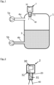
- Figure 1 shows a typical application of a vibronic measuring device 2 as a vibronic point level sensor 2 according to the state of the art.
- the point level sensor 2 is installed in a tank 1 as an overfill protection device. Filling of the tank 1 via an inlet 4a located in an upper area of the tank 1 is effected by a pump 5a and is controlled by the point level sensor 2. If the point level sensor 2 detects a medium 3, the pump 5a is switched off to prevent the tank 1 from overflowing.
- the point level sensor 2 uses a piezoelectric drive as an electromechanical transducer, which acts as a drive and receiver unit 31. Alternatively, electromagnetic transducer units are also possible. A mechanically oscillating unit 40 is excited at its resonant frequency via the electromechanical transducer. The sensor can detect the presence of a medium 3 using the resonant frequency and the amplitude of the oscillation.
- Emptying of the tank 1 takes place via a drain 4b arranged in a lower area, near a bottom of the tank 1, and is effected by a second pump 5b.
- level sensor 2 may detect these vibrations as a measurement signal. This may lead to a malfunction of level sensor 2. If the vibrations from pump 5a are in an area that level sensor 2 would detect as covered, an incorrect switching signal may be output. If the vibrations are in an area that level sensor 2 would detect as uncovered, the exceeding of the limit level cannot be detected, which in the worst case could result in overfilling of tank 1.
- Figure 2 shows a limit level sensor 2 according to the present application.
- An analysis unit 32 capable of detecting external vibrations is integrated into the limit level sensor 2.
- the analysis unit 32 is coupled to a vibration sensor 20, which in the present embodiment is designed as an inertial sensor.
- the vibration sensor 20 is arranged in the limit level sensor 2 such that that, on the one hand, it is mechanically decoupled from the mechanically oscillating unit 40, but on the other hand, it is mechanically coupled to a housing of the point level sensor 2 in such a way that external vibrations acting on the point level sensor 2 can be detected as effectively as possible.
- the vibration sensor 20 is ideally arranged in the area of a process connection 35 of the point level sensor 2 so that, if possible, only the external vibrations acting on the point level sensor 2 are evaluated by the vibration sensor 20. Without mechanical decoupling, the vibrations of the mechanically oscillating unit 40, which are generated by the drive unit 31, cannot be distinguished from external vibrations.
- the analysis unit 32 can also be integrated into the control and evaluation unit 30.
- One function of the analysis unit 32 is supported by integrated artificial intelligence. Various functions can be implemented to improve, stabilize, or adapt the measurement function of the control and evaluation unit 30.
- the electrical received signal S ⁇ , the sensor signal Ss, and the electrical excitation signal SA are supplied to the analysis unit 32 as input signals, each in the time domain and, after a fast Fourier transformation, in the spectral domain.
- a temperature signal T from a temperature sensor arranged adjacent to the mechanically oscillatable unit 40 is supplied to the analysis unit 32 as a further input signal.
- the analysis unit 32 provides reliability information Z, which characterizes a quality and reliability of the received signal SE , Filter parameters for setting an adaptive filter, as well as information about the regularity of interference caused by external vibrations are available.
- the control and evaluation unit 30 Depending on the reliability information Z, this is marked as valid or unreliable by the control and evaluation unit 30.
- the adjustment of the adaptive filter enables an improvement of the reliability information Z.
- countermeasures can be initiated in advance of regularly recurring disturbances, e.g., by increasing the measurement rate, adjusting the filter settings, and/or reducing the influence of the external vibration on the natural vibration, e.g., by increasing the amplitude of the excitation signal SA or by exciting a less or unaffected natural vibration of the mechanically vibratable unit 40.
- pump 5a is not in continuous operation, but only sporadically, this can be detected by the AI. If vibration of pump 5a is detected, the measuring rate of point level sensor 2 can be increased in order to detect reaching a maximum fill level more reliably and quickly.
- the measurement and pump 5a it would also be conceivable for the measurement and pump 5a to be controlled by a common control unit. In this scenario, the operating times of the pump and measurement can alternate. This way, the sensor can be used during a pause in the pumping process to check whether pumping is permitted to continue.
- FIG 3 shows an embodiment of an analysis unit 32 as used in the limit level sensor 2 according to Figure 2 can be used.
- the analysis unit 32 according to Figure 3 indicates in the Figure 3
- the simplified representation shown has six signal inputs 301-306 and four signal outputs 311-314.
- the excitation signal SA in the spectral range SAS is fed to the analysis unit 32 at the first signal input 301.
- the received signal S ⁇ in the time range SEZ and in the spectral range SES is applied to the second and third signal inputs 302, 303.
- the sensor signal is applied to the fourth and fifth signal inputs 304, 305.
- the temperature signal T of the temperature sensor is applied to the sixth signal input 306.
- the reliability information Z can be tapped at the first signal output 301.
- a classifier K for extraneous vibrations can be tapped at the second signal output 302.
- An adjustment signal E for adjusting the adaptive filter can be tapped at the third signal output 303, and a warning signal can be tapped at the fourth signal output 304.
- This warning signal in addition to the reliability information Z, represents a warning when the quality of the input signal falls below a threshold value compared to extraneous vibrations, e.g., in the sense of a signal-to-noise ratio.
Landscapes
- Physics & Mathematics (AREA)
- Fluid Mechanics (AREA)
- General Physics & Mathematics (AREA)
- Acoustics & Sound (AREA)
- Electromagnetism (AREA)
- Thermal Sciences (AREA)
- Engineering & Computer Science (AREA)
- Signal Processing (AREA)
- Measurement Of Mechanical Vibrations Or Ultrasonic Waves (AREA)
Applications Claiming Priority (1)
| Application Number | Priority Date | Filing Date | Title |
|---|---|---|---|
| DE102023125689.0A DE102023125689B3 (de) | 2023-09-21 | 2023-09-21 | Vibronisches Messgerät und Verfahren zur Signalverarbeitung in einem solchen Messgerät |
Publications (1)
| Publication Number | Publication Date |
|---|---|
| EP4528236A1 true EP4528236A1 (fr) | 2025-03-26 |
Family
ID=92208776
Family Applications (1)
| Application Number | Title | Priority Date | Filing Date |
|---|---|---|---|
| EP24192348.1A Withdrawn EP4528236A1 (fr) | 2023-09-21 | 2024-08-01 | Appareil de mesure vibronique et procédé de traitement de signal dans un tel appareil de mesure |
Country Status (4)
| Country | Link |
|---|---|
| US (1) | US20250102347A1 (fr) |
| EP (1) | EP4528236A1 (fr) |
| CN (1) | CN119666136A (fr) |
| DE (1) | DE102023125689B3 (fr) |
Citations (4)
| Publication number | Priority date | Publication date | Assignee | Title |
|---|---|---|---|---|
| DE102012101667A1 (de) | 2012-02-29 | 2013-08-29 | Endress + Hauser Gmbh + Co. Kg | Vibronisches Messgerät |
| EP4095500A1 (fr) * | 2021-05-28 | 2022-11-30 | Endress+Hauser Wetzer GmbH+CO. KG | Thermomètre avec détection de vibrations |
| DE102021129416A1 (de) * | 2021-11-11 | 2023-05-11 | Endress+Hauser SE+Co. KG | Zustandsüberwachung für einen vibronischen Sensor |
| DE102022200917A1 (de) * | 2022-01-27 | 2023-07-27 | Vega Grieshaber Kg | Füllstandmessgerät mit akustischem Sensor |
-
2023
- 2023-09-21 DE DE102023125689.0A patent/DE102023125689B3/de active Active
-
2024
- 2024-08-01 EP EP24192348.1A patent/EP4528236A1/fr not_active Withdrawn
- 2024-09-18 CN CN202411299092.8A patent/CN119666136A/zh active Pending
- 2024-09-18 US US18/888,235 patent/US20250102347A1/en active Pending
Patent Citations (4)
| Publication number | Priority date | Publication date | Assignee | Title |
|---|---|---|---|---|
| DE102012101667A1 (de) | 2012-02-29 | 2013-08-29 | Endress + Hauser Gmbh + Co. Kg | Vibronisches Messgerät |
| EP4095500A1 (fr) * | 2021-05-28 | 2022-11-30 | Endress+Hauser Wetzer GmbH+CO. KG | Thermomètre avec détection de vibrations |
| DE102021129416A1 (de) * | 2021-11-11 | 2023-05-11 | Endress+Hauser SE+Co. KG | Zustandsüberwachung für einen vibronischen Sensor |
| DE102022200917A1 (de) * | 2022-01-27 | 2023-07-27 | Vega Grieshaber Kg | Füllstandmessgerät mit akustischem Sensor |
Also Published As
| Publication number | Publication date |
|---|---|
| DE102023125689B3 (de) | 2025-02-06 |
| US20250102347A1 (en) | 2025-03-27 |
| CN119666136A (zh) | 2025-03-21 |
Similar Documents
| Publication | Publication Date | Title |
|---|---|---|
| EP2483646B1 (fr) | Procédé pour déterminer et/ou contrôler au moins une grandeur de processus physique | |
| EP1529202B1 (fr) | Dispositif pour surveiller un etat de remplissage predefini d'un milieu a mesurer dans un recipient | |
| EP2705336B1 (fr) | Procédé d'opération d'un dispositif pour la détermination et/ou la surveillance d'au moins une grandeur physique | |
| EP1266194B1 (fr) | Procede et dispositif de detection et/ou de controle du niveau d'un fluide dans un conteneur | |
| EP2464951B1 (fr) | Capteur à variables multiples pour la détermination et/ou la surveillance du niveau de remplissage et de la densité et/ou de la viscosité d'un liquide dans un réservoir | |
| EP2831553B1 (fr) | Dispositif de surveillance d'un niveau de liquide | |
| DE102012101667A1 (de) | Vibronisches Messgerät | |
| EP3877732A1 (fr) | Multicapteur vibronique | |
| EP1636553B1 (fr) | Génération d'alerte de formation de dépot au niveau d'appareils de terrain pour la mesure de niveau. | |
| DE102014109843A1 (de) | Verfahren zur Bestimmung des Füllstands in einem Tank | |
| DE102009026685A1 (de) | Verfahren zur Bestimmung oder Überwachung eines vorbestimmten Füllstandes, einer Phasengrenze oder der Dichte eines Mediums | |
| DE102016111134A1 (de) | Vibronischer Sensor | |
| DE102008010113A1 (de) | Verfahren und Vorrichtung zum Überwachen von Fahrwerkregelsystemen | |
| WO2004013585A1 (fr) | Dispositif de determination et/ou de controle d'une grandeur de processus physique ou chimique | |
| WO2003002952A1 (fr) | Dispositif de determination et/ou de surveillance de l'etat de remplissage d'un recipient avec une substance | |
| EP4430367A1 (fr) | Surveillance de l'état pour un capteur vibronique | |
| WO2016091479A1 (fr) | Dispositif et procédé servant à déterminer et/ou surveiller une grandeur de processus | |
| DE102023125689B3 (de) | Vibronisches Messgerät und Verfahren zur Signalverarbeitung in einem solchen Messgerät | |
| WO2010040581A1 (fr) | Dispositif de détermination et/ou de surveillance d'un paramètre de processus d'un fluide | |
| WO2020207699A1 (fr) | Surveillance de l'état d'un capteur vibronique | |
| EP1800093B1 (fr) | Dispositif pour determiner et/ou controler une grandeur de processus d'un milieu | |
| WO2014146980A1 (fr) | Dispositif de détermination et/ou de surveillance d'une grandeur de processus d'un milieu | |
| WO2024083409A1 (fr) | Capteur vibronique | |
| DE3314872A1 (de) | Einrichtung zur meldung des fuellstandes an dem ort eines sensors | |
| DE102010028161B4 (de) | Verfahren und Vorrichtung zur Bestimmung und/oder Überwachung eines Grenzfüllstands |
Legal Events
| Date | Code | Title | Description |
|---|---|---|---|
| PUAI | Public reference made under article 153(3) epc to a published international application that has entered the european phase |
Free format text: ORIGINAL CODE: 0009012 |
|
| STAA | Information on the status of an ep patent application or granted ep patent |
Free format text: STATUS: THE APPLICATION HAS BEEN PUBLISHED |
|
| AK | Designated contracting states |
Kind code of ref document: A1 Designated state(s): AL AT BE BG CH CY CZ DE DK EE ES FI FR GB GR HR HU IE IS IT LI LT LU LV MC ME MK MT NL NO PL PT RO RS SE SI SK SM TR |
|
| STAA | Information on the status of an ep patent application or granted ep patent |
Free format text: STATUS: THE APPLICATION IS DEEMED TO BE WITHDRAWN |
|
| 18D | Application deemed to be withdrawn |
Effective date: 20250927 |