EP4528247A1 - System zur bestimmung des gehaltes an mindestens einer verunreinigung in einer kryogenen flüssigkeit - Google Patents
System zur bestimmung des gehaltes an mindestens einer verunreinigung in einer kryogenen flüssigkeit Download PDFInfo
- Publication number
- EP4528247A1 EP4528247A1 EP24198484.8A EP24198484A EP4528247A1 EP 4528247 A1 EP4528247 A1 EP 4528247A1 EP 24198484 A EP24198484 A EP 24198484A EP 4528247 A1 EP4528247 A1 EP 4528247A1
- Authority
- EP
- European Patent Office
- Prior art keywords
- cryogenic liquid
- vaporization
- content
- impurity
- determining
- Prior art date
- Legal status (The legal status is an assumption and is not a legal conclusion. Google has not performed a legal analysis and makes no representation as to the accuracy of the status listed.)
- Granted
Links
Images
Classifications
-
- G—PHYSICS
- G01—MEASURING; TESTING
- G01N—INVESTIGATING OR ANALYSING MATERIALS BY DETERMINING THEIR CHEMICAL OR PHYSICAL PROPERTIES
- G01N1/00—Sampling; Preparing specimens for investigation
- G01N1/28—Preparing specimens for investigation including physical details of (bio-)chemical methods covered elsewhere, e.g. G01N33/50, C12Q
- G01N1/40—Concentrating samples
- G01N1/4022—Concentrating samples by thermal techniques; Phase changes
-
- F—MECHANICAL ENGINEERING; LIGHTING; HEATING; WEAPONS; BLASTING
- F25—REFRIGERATION OR COOLING; COMBINED HEATING AND REFRIGERATION SYSTEMS; HEAT PUMP SYSTEMS; MANUFACTURE OR STORAGE OF ICE; LIQUEFACTION SOLIDIFICATION OF GASES
- F25J—LIQUEFACTION, SOLIDIFICATION OR SEPARATION OF GASES OR GASEOUS OR LIQUEFIED GASEOUS MIXTURES BY PRESSURE AND COLD TREATMENT OR BY BRINGING THEM INTO THE SUPERCRITICAL STATE
- F25J3/00—Processes or apparatus for separating the constituents of gaseous or liquefied gaseous mixtures involving the use of liquefaction or solidification
- F25J3/02—Processes or apparatus for separating the constituents of gaseous or liquefied gaseous mixtures involving the use of liquefaction or solidification by rectification, i.e. by continuous interchange of heat and material between a vapour stream and a liquid stream
- F25J3/04—Processes or apparatus for separating the constituents of gaseous or liquefied gaseous mixtures involving the use of liquefaction or solidification by rectification, i.e. by continuous interchange of heat and material between a vapour stream and a liquid stream for air
- F25J3/04406—Processes or apparatus for separating the constituents of gaseous or liquefied gaseous mixtures involving the use of liquefaction or solidification by rectification, i.e. by continuous interchange of heat and material between a vapour stream and a liquid stream for air using a dual pressure main column system
- F25J3/04412—Processes or apparatus for separating the constituents of gaseous or liquefied gaseous mixtures involving the use of liquefaction or solidification by rectification, i.e. by continuous interchange of heat and material between a vapour stream and a liquid stream for air using a dual pressure main column system in a classical double column flowsheet, i.e. with thermal coupling by a main reboiler-condenser in the bottom of low pressure respectively top of high pressure column
-
- F—MECHANICAL ENGINEERING; LIGHTING; HEATING; WEAPONS; BLASTING
- F25—REFRIGERATION OR COOLING; COMBINED HEATING AND REFRIGERATION SYSTEMS; HEAT PUMP SYSTEMS; MANUFACTURE OR STORAGE OF ICE; LIQUEFACTION SOLIDIFICATION OF GASES
- F25J—LIQUEFACTION, SOLIDIFICATION OR SEPARATION OF GASES OR GASEOUS OR LIQUEFIED GASEOUS MIXTURES BY PRESSURE AND COLD TREATMENT OR BY BRINGING THEM INTO THE SUPERCRITICAL STATE
- F25J3/00—Processes or apparatus for separating the constituents of gaseous or liquefied gaseous mixtures involving the use of liquefaction or solidification
- F25J3/02—Processes or apparatus for separating the constituents of gaseous or liquefied gaseous mixtures involving the use of liquefaction or solidification by rectification, i.e. by continuous interchange of heat and material between a vapour stream and a liquid stream
- F25J3/04—Processes or apparatus for separating the constituents of gaseous or liquefied gaseous mixtures involving the use of liquefaction or solidification by rectification, i.e. by continuous interchange of heat and material between a vapour stream and a liquid stream for air
- F25J3/04763—Start-up or control of the process; Details of the apparatus used
- F25J3/04769—Operation, control and regulation of the process; Instrumentation within the process
-
- F—MECHANICAL ENGINEERING; LIGHTING; HEATING; WEAPONS; BLASTING
- F25—REFRIGERATION OR COOLING; COMBINED HEATING AND REFRIGERATION SYSTEMS; HEAT PUMP SYSTEMS; MANUFACTURE OR STORAGE OF ICE; LIQUEFACTION SOLIDIFICATION OF GASES
- F25J—LIQUEFACTION, SOLIDIFICATION OR SEPARATION OF GASES OR GASEOUS OR LIQUEFIED GASEOUS MIXTURES BY PRESSURE AND COLD TREATMENT OR BY BRINGING THEM INTO THE SUPERCRITICAL STATE
- F25J3/00—Processes or apparatus for separating the constituents of gaseous or liquefied gaseous mixtures involving the use of liquefaction or solidification
- F25J3/02—Processes or apparatus for separating the constituents of gaseous or liquefied gaseous mixtures involving the use of liquefaction or solidification by rectification, i.e. by continuous interchange of heat and material between a vapour stream and a liquid stream
- F25J3/04—Processes or apparatus for separating the constituents of gaseous or liquefied gaseous mixtures involving the use of liquefaction or solidification by rectification, i.e. by continuous interchange of heat and material between a vapour stream and a liquid stream for air
- F25J3/04763—Start-up or control of the process; Details of the apparatus used
- F25J3/04769—Operation, control and regulation of the process; Instrumentation within the process
- F25J3/04854—Safety aspects of operation
- F25J3/0486—Safety aspects of operation of vaporisers for oxygen enriched liquids, e.g. purging of liquids
-
- G—PHYSICS
- G01—MEASURING; TESTING
- G01N—INVESTIGATING OR ANALYSING MATERIALS BY DETERMINING THEIR CHEMICAL OR PHYSICAL PROPERTIES
- G01N1/00—Sampling; Preparing specimens for investigation
- G01N1/28—Preparing specimens for investigation including physical details of (bio-)chemical methods covered elsewhere, e.g. G01N33/50, C12Q
- G01N1/40—Concentrating samples
-
- F—MECHANICAL ENGINEERING; LIGHTING; HEATING; WEAPONS; BLASTING
- F25—REFRIGERATION OR COOLING; COMBINED HEATING AND REFRIGERATION SYSTEMS; HEAT PUMP SYSTEMS; MANUFACTURE OR STORAGE OF ICE; LIQUEFACTION SOLIDIFICATION OF GASES
- F25J—LIQUEFACTION, SOLIDIFICATION OR SEPARATION OF GASES OR GASEOUS OR LIQUEFIED GASEOUS MIXTURES BY PRESSURE AND COLD TREATMENT OR BY BRINGING THEM INTO THE SUPERCRITICAL STATE
- F25J2280/00—Control of the process or apparatus
- F25J2280/02—Control in general, load changes, different modes ("runs"), measurements
-
- G—PHYSICS
- G01—MEASURING; TESTING
- G01N—INVESTIGATING OR ANALYSING MATERIALS BY DETERMINING THEIR CHEMICAL OR PHYSICAL PROPERTIES
- G01N1/00—Sampling; Preparing specimens for investigation
- G01N1/28—Preparing specimens for investigation including physical details of (bio-)chemical methods covered elsewhere, e.g. G01N33/50, C12Q
- G01N1/40—Concentrating samples
- G01N1/4022—Concentrating samples by thermal techniques; Phase changes
- G01N2001/4027—Concentrating samples by thermal techniques; Phase changes evaporation leaving a concentrated sample
Definitions
- the present invention relates to the chemical industry and concerns a system for determining the content of at least one dissolved impurity in a cryogenic liquid, for example taken from an air gas separation system, as well as a corresponding determination method.
- An air separation system consists of low- and medium-pressure distillation columns to separate the various constituents of air. Although the air is purified before entering the columns, impurities remain in the air fed to the columns and are concentrated, for example, in an oxygen vaporizer in one of the columns.
- the impurity present in the vaporizer is not reactive with oxygen, it accelerates the accumulation phenomenon of all the others impurities, therefore also impurities reactive with oxygen. This is particularly the case for carbon dioxide and nitrous oxide, whose solidification temperature is higher than the operating temperature of liquid oxygen. These impurities may not be stopped by adsorption processes and create a solid phase in the liquid oxygen of the vaporizer, which can block the vaporization channels of the vaporizer. This mechanism, called “dead end boiling” or “dead-end boiling”, accelerates the concentration of all the impurities contained in the vaporizing liquid, particularly hydrocarbons, and therefore increases the risk of combustion of the vaporization matrix.
- the inventors have designed an apparatus and a method for analyzing this content, described in the documents FR3066596 And FR3066597
- the device allows the vaporization of a large quantity of a sample of cryogenic liquid to be analyzed in a capacity, the gas thus vaporized being evacuated in an open circuit, a residual quantity of cryogenic liquid in which the impurities of the sample have concentrated, being retained at the end of this vaporization. Then the capacity is kept closed and the residual quantity of cryogenic liquid is entirely vaporized in the capacity, so as to obtain a gas with a much higher impurity content than that of the initial sample, therefore easier to measure by a gas analyzer.
- This innovative approach requires that the impurities whose concentration is to be measured are less volatile than the cryogenic liquid in which they are present, but also that the quantity of impurities evaporating during open-circuit vaporization is negligible compared to the quantity of impurities remaining in the residual cryogenic liquid.
- These conditions depend on the thermodynamic equilibrium values between the impurities and their solvent, which themselves depend on the vaporization temperature and pressure. The lower the vaporization pressure, the more favorable vaporization is for the concentration of impurities in the residual cryogenic liquid. Based on these thermodynamic equilibrium values, the concentration of impurities in the residual cryogenic liquid should not be a problem.
- the quantity of nitrous oxide, or carbon dioxide, or propane, escaping as vapour during vaporization in an open circuit remains less than 2% of the quantity of impurities remaining in the cryogenic liquid.
- the inventors have found that the amount of impurities escaping into the gas phase during open-circuit vaporization can actually be much greater when the vaporized cryogenic liquid has areas of over-concentration of impurities, or when dry vaporization of the cryogenic liquid takes place on the wall of the apparatus which transmits the heat of vaporization.
- the concentration of impurities can be done at a pressure higher than atmospheric pressure, but this does not prevent the formation of over-concentrated areas of impurities in the liquid.
- the present invention aims to remedy at least in part the aforementioned drawbacks by providing a system and a method for determining the content of at least one impurity in a cryogenic liquid, as well as a system for separating gases from air, which make it possible to concentrate the impurity in a portion of the liquid before vaporization of this part of the liquid and sending the vapor thus produced into a gas analyzer, with a concentration factor which is not distorted by excessive vaporization of the impurities during the concentration of the impurity in the part of the cryogenic liquid.
- the vaporization means are configured to keep said heating surface wet with the volume of residual cryogenic liquid.
- the vaporization of the initial volume of cryogenic liquid making it possible to concentrate the impurity in the volume of residual cryogenic liquid, is done without the impurity escaping in a significant manner into the gaseous phase during this vaporization.
- the heating surface of the vaporization means which allows this vaporization is entirely submerged or entirely wetted by the volume of residual cryogenic liquid. There is therefore no dry vaporization of the cryogenic liquid which could create deposits on this heating surface. This is defined as allowing the vaporization of the cryogenic liquid, therefore releasing heat allowing this vaporization.
- Other surfaces of the vaporization means can be relatively hot compared to the cryogenic liquid without allowing it to vaporize.
- the heating surface is, for example, arranged in the lower part of the capacity.
- thermosiphon effect produced by the vaporization means, allows the cryogenic liquid to be agitated and therefore prevents the formation of areas over-concentrated in impurities in the cryogenic liquid, which also prevents excessive vaporization of these impurities.
- the discharge conduits are those which allow the vaporization of the cryogenic liquid, their internal surface heating the cryogenic liquid to a temperature allowing this vaporization.
- the vaporization means are for example arranged in a lower part of the capacity so as to at least partially submerge the discharge conduits in the volume of residual cryogenic liquid by the effect of gravity, the internal surface of the discharge conduits even not submerged by the residual cryogenic liquid, remaining wet by the circulation of residual cryogenic liquid in the discharge conduits due to the thermosiphon effect.
- the exhaust ducts surround, for example, the inlet duct.
- the exhaust ducts are preferably smaller in diameter than the inlet duct.
- the lower part of the capacity forms, for example, a portion of the lower part of the capacity, with the same surface area as the face of the body, corresponding to a base of its cylindrical shape.
- This face is therefore flat if we disregard the orifices of the conduits opening onto this face.
- This is, for example, flush with the lower part of the capacity, in order to allow the evaporation means to collect by gravity the entire volume of residual cryogenic liquid, forming for example one percent or less than one percent of the initial volume of cryogenic liquid.
- the conduits are therefore arranged vertically relative to the ground, the face delimiting the lower part of the capacity being arranged horizontally.
- the thermally conductive body is a good thermal conductor, for example made of copper or aluminum and preferably forming a single piece.
- the surface of this body is for example smooth or textured, in particular the internal surfaces of the exhaust ducts have for example a surface which improves the vaporization exchange coefficient and/or the wetting of the wall by its roughness, its texturing geometry, the presence of micro-fins or other means.
- the body comprises a thermally insulating jacket arranged between the intake duct and the exhaust ducts.
- This insulating jacket is for example made of polytetrafluoroethylene (also called “Teflon® ” ).
- the vaporization means comprise in particular at least one electric heating member arranged in a recess of the body proximal to the exhaust ducts. This heating member is for example a heating resistor or a heating cartridge, arranged between the intake duct and the exhaust ducts, or around the exhaust ducts.
- the vaporization means comprise several electric heating members in the form of heating cartridges, the body comprising spaces arranged around the discharge ducts and housing the heating cartridges, the spaces not opening onto the face of the body delimiting the lower part of the capacity.
- These spaces extend parallel to the discharge ducts, at a distance from them in the thermally conductive body, but close enough to maintain the internal surfaces of the discharge ducts at a temperature allowing the vaporization of the cryogenic liquid. They are preferably arranged uniformly angularly around the discharge ducts.
- the spaces are for example separated by recesses on the circumference of the body, over at least part of the height of the body. These recesses limit the mass of the body to be heated by the heating cartridges during the vaporization of the cryogenic liquid, but also the mass of the body to be cooled during a subsequent step aimed at bringing the walls of the capacity to a filling temperature. This subsequent step is necessary to carry out a new determination of the impurity content in a new initial volume of cryogenic liquid, which must be able to be accurately assessed when it fills the capacity.
- the recesses between the spaces housing the heating cartridges give, for example, a barrel shape to the body in the overall shape of a cylinder, by opening onto the external cylindrical wall of the body. They allow a reduction in the cost of the determination system according to the invention.
- the body has a face opposite the face delimiting the lower part of the capacity and the vaporization means comprise in particular a collector arranged on the opposite face, the collector fluidly connecting the intake duct with the discharge ducts.
- This collector is for example a copper part added to the opposite face of the body, comprising a fluid circulation chamber.
- the collector being arranged vertically under the body, it is always filled with residual cryogenic liquid and therefore does not allow the formation of impurity deposits.
- a jacket surrounds the vaporization means, the jacket being configured to contain a cooling liquid coming into contact with the vaporization means.
- other cooling means are conceivable.
- the envelope is for example an annular envelope surrounding at least the lower part of the capacity, this being for example a cylindrical tank.
- the opposite face opens out of the casing, the intake and exhaust ducts extending from the face delimiting the lower part of the capacity, through the casing.
- the opposite face includes, for example, orifices for inserting the heating cartridges into the spaces. The installation and replacement of these cartridges are thus also facilitated.
- the invention also relates to a system for separating air gases by cryogenic distillation comprising a system for determining the content of at least one impurity dissolved in a cryogenic liquid according to the invention, means for sampling fluid circulating in the separation system, means for liquefying the sampled fluid if it is gaseous, and means for sending the sampled fluid, possibly liquefied, into the capacity to determine its content of the impurity.
- system and the method for determining the content of at least one dissolved impurity in a cryogenic liquid of the invention are applicable to other systems, for example to a system for separating another type of gas, from which one would like to separate, for example, carbon dioxide.
- the vaporization step is carried out at atmospheric pressure or under controlled vacuum through a vacuum production system such as a vacuum pump or an ejector.
- a vacuum production system such as a vacuum pump or an ejector.
- the pressure within the capacity during the vaporization step is brought to a value between 0.2 bar and 0.3 bar and preferably equal to 0.2 bar. This makes it possible to lower the vaporization temperature and consequently to further reduce the liquid/vapor equilibrium coefficients. In addition, this increases the temperature difference between the heating surface and the cryogenic liquid, which makes it possible to reduce the duration of the vaporization step.
- the amount of cryogenic liquid vaporized during the vaporization step is controlled so as to precisely know the concentration factor corresponding to the ratio between the initial volume of cryogenic liquid and the volume of residual cryogenic liquid. This can be done by monitoring the duration of the vaporization step as well as the temperature and pressure parameters during this vaporization step.
- the determination step involves sampling the residual cryogenic liquid and then vaporizing the sampled liquid into a gas, or vaporizing all the residual cryogenic liquid into a gas, and then sending the gas obtained by vaporizing the sampled liquid or all the residual cryogenic liquid into a gas analyzer.
- the gas analyzer must detect a concentrated impurity content and therefore does not need to be very precise and very expensive.
- the determination method according to the invention comprises a step of emptying the capacity, followed by a step of cooling the capacity by introducing into the casing of the determination system, a liquid at a temperature lower than or equal to the filling temperature of the cryogenic liquid.
- the emptying step follows the removal of the residual cryogenic liquid, or the sending of the gas obtained by vaporization of all the residual cryogenic liquid, so as not to disturb the determination of the impurity content carried out by the gas analyzer.
- the capacity can accommodate a new initial volume of cryogenic liquid. taken from the air gas separation system, to carry out a new determination of the impurity content.
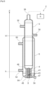
- a method 100 for determining the content of at least one dissolved impurity in a cryogenic liquid according to the invention is implemented by a system 2 for determining the content of at least one dissolved impurity in a cryogenic liquid according to the invention represented Figure 2 , this system 2 being part of a system for separating air gases by cryogenic distillation according to the invention.
- the at least one impurity whose content is determined is, for example, propane.
- the contents of impurities other than propane in the cryogenic liquid are of course also preferably determined by the determination method 100, the determination system 2 allowing these multiple determinations.
- the impurities determined in this embodiment of the invention are less volatile than the cryogenic liquid.
- This air gas separation system comprises means for sampling fluid circulating in the separation system.
- these sampling means sample liquid oxygen at the inlet of an oxygen vaporizer of the gas separation system, this oxygen vaporizer being arranged in a distillation column of the gas separation system. The liquid oxygen thus sampled is sent to the determination system 2.
- Capacity 3 comprises a capacity 3 in the form of a cylindrical tank, capable of containing liquid oxygen, and arranged vertically on feet not shown.
- Capacity 3 comprises a liquid inlet 32, a liquid outlet 34 and a gas outlet 36.
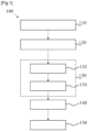
- the liquid oxygen taken from the separation system is sent into the capacity 3, via the liquid inlet 32 on the capacity 3, during a first step 110 of the determination method 100, which is a step of filling the capacity 3 with an initial volume of cryogenic liquid, i.e. here liquid oxygen.
- This initial volume of cryogenic liquid is predetermined.
- the capacity 3 is filled until the cryogenic liquid overflows from the capacity 3 through the liquid outlet 34, the position of which on the capacity 3 is determined so that the capacity 3 is filled with the predetermined initial volume of cryogenic liquid when it reaches the liquid outlet 34.
- the height of the cryogenic liquid in the capacity 3 is then h 1. This height is measured vertically relative to the ground along a vertical axis Z.
- the pressure and temperature of the cryogenic liquid prevent it from vaporizing.
- the temperature of the cryogenic liquid is notably lower than its vaporization temperature at the pressure to which it is subjected during this step.
- the next step of the determination method 100 is a step 120 of vaporizing the cryogenic liquid until a volume of residual cryogenic liquid is obtained.
- the liquid inlet 32 and outlet 34 on the capacity 3 are closed, while a gas outlet 36, arranged at the top of the capacity 3, is open. Indeed, the cryogenic liquid transformed into vapor is evacuated during this vaporization step 120, through the gas outlet 36.
- This vaporization is carried out by vaporization means 84 arranged in the lower part of the capacity 3, which bring the cryogenic liquid to its vaporization temperature, the vaporization pressure in capacity 3 being pulled under vacuum to a pressure of approximately 0.2 bar absolute. Thanks to this low pressure, the vaporization temperature (or bubble temperature) is lower than at atmospheric pressure, which reduces the duration of the vaporization step 120. In addition, this low pressure reduces the liquid/vapor equilibrium coefficients, avoiding the escape of a significant quantity of impurities into the gas phase.
- the concentration factor of the impurities in the volume of residual cryogenic liquid is precisely determined as the ratio between the initial volume of cryogenic liquid and the volume of residual cryogenic liquid.
- the capacity 3 has a capacity of 1.3 liters and the initial volume of cryogenic liquid is 0.8 liters.
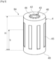
- the vaporization means 84 are more particularly visible on the Figure 3 They comprise a copper body 4, generally in the form of a cylinder of height H. The body 4 is arranged along this height H vertically in the lower part of the capacity 3, so that a face 46 of the body corresponding to a base of the cylinder, is arranged horizontally and forms a lower part of the capacity 3. In other words the bottom of the cylindrical tank forming the capacity 3 is constituted in part by the face 46 of the body 4, which is flush with the aluminum walls of the cylindrical tank.
- An opposite face 48 of the body 4 corresponding to the other base of the cylinder, is therefore arranged horizontally proximal to the ground relative to the face 46 forming the lower part of the capacity 3.
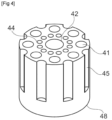
- the body 4 is crossed along its height by conduits 43 arranged vertically, namely an intake conduit 42, in the center of the body 4, and conduits evacuation 44 surrounding the intake duct 42.
- the evacuation ducts 44 are of smaller diameter than the intake duct 42.
- a copper collector 8 is attached to the opposite face 48 so as to fluidly communicate the intake duct 42 and the evacuation ducts 44.
- the collector 8 is part of the vaporization means 84.
- the lower part of the capacity 3 and the vaporization means 84 form sealed means for retaining the cryogenic liquid.
- the vaporization means 84 also comprise heating cartridges housed in spaces 41 (visible Figure 4 ) arranged in the body 4 around the evacuation conduits 44. These spaces 41 extend parallel to the evacuation conduits 44 in the body 4, without opening onto the face 46 forming the lower part of the capacity 3. They however open onto the opposite face 48 in order to allow the insertion of the heating cartridges into these cavities 41 as well as the electrical supply of these heating cartridges.
- the envelope 5 takes the form of an annular envelope of which a first circular edge surrounds the body 4 by bordering the opposite face 48 and of which a second circular edge surrounds the capacity 3 slightly below the liquid outlet 34 on the capacity 3. The usefulness of this envelope 5 will be described later.
- the vaporization means 84 operate as a bath vaporizer with a thermosiphon effect in the discharge conduits 44. Indeed, during the vaporization step 120, the heating cartridges are powered, and bring the temperature of the cryogenic liquid present in the discharge conduits 44 to its vaporization temperature, allowing the vaporized oxygen to escape with very few impurities towards the gas outlet 36. A circulation is created due to the thermal flows, the cryogenic liquid circulating in the intake conduit 42 from the face 46 to the opposite face 48 of the body 4, then passing through the collector 8 to supply the discharge conduits 44 with cryogenic liquid.
- This circulation allows good agitation and good homogeneity of the cryogenic liquid in the vaporization means 84 and in particular at the level of its heating surface formed by the internal surfaces of the discharge conduits 44.
- the vaporization means 84 are configured so that this heating surface is still submerged in the cryogenic liquid or wetted by it at the end of the evaporation step 120, when the volume of non-vaporized cryogenic liquid reaches the predetermined volume of residual cryogenic liquid.
- the body 4 has a height H of 7 mm (millimeters), and the height h reached by the volume of residual cryogenic liquid in the capacity is not less than 50% of the height H of the body 4.
- the circulation operated by thermosiphon effect in the discharge conduits 44 thus makes it possible to keep their internal surfaces wetted.
- the heating surface which is a vaporization surface, transmits the heat of vaporization without vaporizing dry even locally.
- the internal surface of the latter is covered with a thermally insulating jacket 47, for example made of Teflon ® .
- the heat flow in the vaporization means is controlled, which makes it possible to control the temperature of the heating surface.
- the body 4 through its material, makes it possible to homogenize the temperature of the internal surfaces of the evacuation conduits 44.
- the configuration of the body 4 and in particular the arrangement of its conduits 43, makes it possible to have a large, always wet heating surface although the volume of residual cryogenic liquid is very small.
- the thermal power of these vaporization means 84 makes it possible to vaporize 99% of the initial volume of cryogenic liquid, in less than 15 minutes.
- the gas outlet 36 is closed, the capacity being isolated and containing the predetermined volume of residual cryogenic liquid.
- the following step is then a step 130 of determining the impurity content of the residual cryogenic liquid.
- This determination step 130 involves the vaporization 132 of the entire volume of residual cryogenic liquid, in the capacity 3 kept closed, then the sending 134 of the gas thus vaporized and concentrated in impurities, into a gas analyzer 6 (represented Figure 2 ). This determines the propane content of the gas, then this content is divided by the concentration factor to determine the propane content in the liquid oxygen taken from the air gas separation system.
- the contents of other types of impurities can also be determined in this determination step 130, in the same way, in particular the nitrous oxide content and the carbon dioxide content in the liquid oxygen taken from the air gas separation system.
- the next step is a step 140 of emptying the capacity 3, for example by sending a neutral gas free of impurities into the capacity 3.
- the gas remaining in the capacity is drawn under vacuum by an ejector or a vacuum pump.
- the capacity 3 is cooled during a cooling step 150, during which a liquid at a temperature lower than or equal to the filling temperature of the cryogenic liquid, is sent into the casing 5 through a liquid inlet 52 with which the casing 5 is provided in its lower part.
- This liquid is for example liquid oxygen.
- a gas outlet 56 in an upper part of the casing makes it possible to release a gaseous phase produced by evaporation of the liquid in the casing 5 in contact with the hot wall of the capacity 3.
- the coolant is evacuated from the casing 5 through an outlet 54 located in the lower part of the casing 5, and the determination system 2 is ready for a new implementation of the determination method 100.
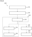
- a variant of the determination method 100 according to the invention is now presented in relation to the Figure 5 , showing the steps of a determination method 200 according to the invention.
- the determination method 200 comprises steps 210 of filling the capacity 3 and 220 of vaporization of the cryogenic liquid, which are identical to the steps 110 of filling and 120 of vaporization respectively described previously.
- the entire volume of residual cryogenic liquid is not vaporized, but a predetermined volume of this volume of residual cryogenic liquid is taken 232, it is vaporized 234 entirely and it is sent 236 to the gas analyzer 6.
- the latter determines the impurity content in the same way as in the determination step 130.
- This variant makes it possible to carry out a step 240 of emptying the capacity 3, in parallel with the vaporization of the cryogenic liquid sample in the separate capacity.
- the cryogenic liquid remaining in the capacity 3 is for example vaporized and evacuated via the gas outlet 36 on the capacity 3.
- the capacity 3 is cooled during a cooling step 250, identical to the cooling step 150 of the determination method 100.
- the determination system 2 is then ready for a new implementation of the determination method 200.
- the invention is described in the context of a cryogenic liquid originating from the separation of air, such as oxygen, nitrogen or argon. It goes without saying that the invention applies to any cryogenic liquid, for example carbon dioxide, carbon monoxide, hydrogen, helium, methane, krypton, xenon, neon.
Landscapes
- Engineering & Computer Science (AREA)
- Physics & Mathematics (AREA)
- Mechanical Engineering (AREA)
- Thermal Sciences (AREA)
- General Engineering & Computer Science (AREA)
- Analytical Chemistry (AREA)
- Life Sciences & Earth Sciences (AREA)
- Chemical & Material Sciences (AREA)
- Health & Medical Sciences (AREA)
- Biochemistry (AREA)
- General Health & Medical Sciences (AREA)
- General Physics & Mathematics (AREA)
- Immunology (AREA)
- Pathology (AREA)
- Separation By Low-Temperature Treatments (AREA)
- Filling Or Discharging Of Gas Storage Vessels (AREA)
Applications Claiming Priority (1)
| Application Number | Priority Date | Filing Date | Title |
|---|---|---|---|
| FR2309982A FR3153406B1 (fr) | 2023-09-21 | 2023-09-21 | Système de détermination de la teneur en au moins une impureté dans un liquide cryogénique |
Publications (2)
| Publication Number | Publication Date |
|---|---|
| EP4528247A1 true EP4528247A1 (de) | 2025-03-26 |
| EP4528247B1 EP4528247B1 (de) | 2026-03-04 |
Family
ID=89158381
Family Applications (1)
| Application Number | Title | Priority Date | Filing Date |
|---|---|---|---|
| EP24198484.8A Active EP4528247B1 (de) | 2023-09-21 | 2024-09-04 | System zur bestimmung des gehaltes an mindestens einer verunreinigung in einer kryogenen flüssigkeit |
Country Status (5)
| Country | Link |
|---|---|
| US (1) | US20250102406A1 (de) |
| EP (1) | EP4528247B1 (de) |
| JP (1) | JP2025048797A (de) |
| CN (1) | CN119666518A (de) |
| FR (1) | FR3153406B1 (de) |
Citations (4)
| Publication number | Priority date | Publication date | Assignee | Title |
|---|---|---|---|---|
| FR3066597A1 (fr) | 2017-05-19 | 2018-11-23 | L'air Liquide, Societe Anonyme Pour L'etude Et L'exploitation Des Procedes Georges Claude | Appareil d'analyse des traces de contaminants d'un liquide cryogenique |
| FR3066596A1 (fr) | 2017-05-19 | 2018-11-23 | L'air Liquide, Societe Anonyme Pour L'etude Et L'exploitation Des Procedes Georges Claude | Procede d'analyse des traces de contaminants d'un liquide cryogenique |
| US20200191689A1 (en) * | 2017-05-19 | 2020-06-18 | L'air Liquide, Societe Anonyme Pour L'etude Et L'exploitation Des Procedes Georges Claude | Method for analyzing traces of contaminants of a cryogenic liquid |
| US20220163432A1 (en) * | 2020-11-26 | 2022-05-26 | L'air Liquide, Societe Anonyme Pour L'etude Et L?Exploitation Des Procedes Georges Claude | Process and device for vaporizing purge liquid from a cryogenic liquid vaporizer |
-
2023
- 2023-09-21 FR FR2309982A patent/FR3153406B1/fr active Active
-
2024
- 2024-09-04 EP EP24198484.8A patent/EP4528247B1/de active Active
- 2024-09-19 CN CN202411305685.0A patent/CN119666518A/zh active Pending
- 2024-09-19 JP JP2024161578A patent/JP2025048797A/ja active Pending
- 2024-09-20 US US18/890,893 patent/US20250102406A1/en active Pending
Patent Citations (4)
| Publication number | Priority date | Publication date | Assignee | Title |
|---|---|---|---|---|
| FR3066597A1 (fr) | 2017-05-19 | 2018-11-23 | L'air Liquide, Societe Anonyme Pour L'etude Et L'exploitation Des Procedes Georges Claude | Appareil d'analyse des traces de contaminants d'un liquide cryogenique |
| FR3066596A1 (fr) | 2017-05-19 | 2018-11-23 | L'air Liquide, Societe Anonyme Pour L'etude Et L'exploitation Des Procedes Georges Claude | Procede d'analyse des traces de contaminants d'un liquide cryogenique |
| US20200191689A1 (en) * | 2017-05-19 | 2020-06-18 | L'air Liquide, Societe Anonyme Pour L'etude Et L'exploitation Des Procedes Georges Claude | Method for analyzing traces of contaminants of a cryogenic liquid |
| US20220163432A1 (en) * | 2020-11-26 | 2022-05-26 | L'air Liquide, Societe Anonyme Pour L'etude Et L?Exploitation Des Procedes Georges Claude | Process and device for vaporizing purge liquid from a cryogenic liquid vaporizer |
Also Published As
| Publication number | Publication date |
|---|---|
| US20250102406A1 (en) | 2025-03-27 |
| CN119666518A (zh) | 2025-03-21 |
| JP2025048797A (ja) | 2025-04-03 |
| EP4528247B1 (de) | 2026-03-04 |
| FR3153406A1 (fr) | 2025-03-28 |
| FR3153406B1 (fr) | 2025-08-22 |
Similar Documents
| Publication | Publication Date | Title |
|---|---|---|
| CA2656806C (fr) | Procede de prelevement automatique du tritium dans la vapeur d'eau de l'air | |
| FR2533304A1 (fr) | Appareil de refrigeration pour le refroidissement rapide de specimens, en particulier, biologiques | |
| EP0349042A2 (de) | System zur automatischen Kontrolle von integrierten Schaltungen | |
| EP4006469B1 (de) | Verfahren und vorrichtung zum verdampfen von spülflüssigkeit aus einem verdampfer für kryogene flüssigkeiten | |
| EP1357341A1 (de) | Verfahren und kryogene Flüssigkeiten Probenahmeeinrichtung, sowie Luftzerlegungsanlage mit solcher Einrichtung | |
| FR2769354A1 (fr) | Procede et installation de remplissage d'un reservoir sous pression | |
| WO2021123554A1 (fr) | Dispositif de régulation thermique pour un composant électrique | |
| EP4528247B1 (de) | System zur bestimmung des gehaltes an mindestens einer verunreinigung in einer kryogenen flüssigkeit | |
| FR2545588A1 (fr) | Appareil de refrigeration et piege frigorifique comprenant un tel appareil | |
| EP3625536B1 (de) | Vorrichtung zur behandlung einer zu analysierenden flüssigkeit | |
| EP0188976A1 (de) | Mischkryostat | |
| EP2584294B1 (de) | Vorrichtung zur kaltgaseinspeisung einer nmr-anlage | |
| EP4528193B1 (de) | Verfahren und system zur bestimmung des gehalts mindestens einer verunreinigung in einer kryogenen flüssigkeit | |
| EP2203729B1 (de) | Zweiphasenübergangs-nuklearkalorimeter für einen reaktor | |
| EP3443264B1 (de) | Vorrichtung zur umwandlung einer flüssigkeit in dampf | |
| CH370489A (fr) | Procédé cryogénique d'irradiation à basse température d'un échantillon de matière et dispositif pour sa mise en oeuvre | |
| EP0177416A1 (de) | Kryostatische Vorrichtung für Strahlungsdetektoren | |
| FR3066596A1 (fr) | Procede d'analyse des traces de contaminants d'un liquide cryogenique | |
| FR3066597A1 (fr) | Appareil d'analyse des traces de contaminants d'un liquide cryogenique | |
| FR2754598A1 (fr) | Dilatometre basse temperature de precision | |
| EP1616139A1 (de) | Verfahren und vorrichtung zur behandlung eines sauerstoffreichen flüssigkeitbades im sumpfteil einer tieftemperatur-destillationsäule | |
| FR2797325A1 (fr) | Procede et appareil de detection et d'analyse de composes en phase liquide ou solide et unite de distillation comprenant un tel appareil | |
| FR2858416A1 (fr) | Procedes d'analyse de liquides cryogeniques et analyseur | |
| FR2618016A1 (fr) | Dispositif de refroidissement d'un aimant resistif |
Legal Events
| Date | Code | Title | Description |
|---|---|---|---|
| PUAI | Public reference made under article 153(3) epc to a published international application that has entered the european phase |
Free format text: ORIGINAL CODE: 0009012 |
|
| STAA | Information on the status of an ep patent application or granted ep patent |
Free format text: STATUS: THE APPLICATION HAS BEEN PUBLISHED |
|
| AK | Designated contracting states |
Kind code of ref document: A1 Designated state(s): AL AT BE BG CH CY CZ DE DK EE ES FI FR GB GR HR HU IE IS IT LI LT LU LV MC ME MK MT NL NO PL PT RO RS SE SI SK SM TR |
|
| STAA | Information on the status of an ep patent application or granted ep patent |
Free format text: STATUS: REQUEST FOR EXAMINATION WAS MADE |
|
| 17P | Request for examination filed |
Effective date: 20250926 |
|
| GRAP | Despatch of communication of intention to grant a patent |
Free format text: ORIGINAL CODE: EPIDOSNIGR1 |
|
| STAA | Information on the status of an ep patent application or granted ep patent |
Free format text: STATUS: GRANT OF PATENT IS INTENDED |
|
| GRAS | Grant fee paid |
Free format text: ORIGINAL CODE: EPIDOSNIGR3 |
|
| GRAA | (expected) grant |
Free format text: ORIGINAL CODE: 0009210 |
|
| STAA | Information on the status of an ep patent application or granted ep patent |
Free format text: STATUS: THE PATENT HAS BEEN GRANTED |
|
| INTG | Intention to grant announced |
Effective date: 20260115 |
|
| AK | Designated contracting states |
Kind code of ref document: B1 Designated state(s): AL AT BE BG CH CY CZ DE DK EE ES FI FR GB GR HR HU IE IS IT LI LT LU LV MC ME MK MT NL NO PL PT RO RS SE SI SK SM TR |
|
| REG | Reference to a national code |
Ref country code: CH Ref legal event code: F10 Free format text: ST27 STATUS EVENT CODE: U-0-0-F10-F00 (AS PROVIDED BY THE NATIONAL OFFICE) Effective date: 20260304 Ref country code: GB Ref legal event code: FG4D Free format text: NOT ENGLISH |
|
| REG | Reference to a national code |
Ref country code: DE Ref legal event code: R096 Ref document number: 602024002976 Country of ref document: DE |
|
| REG | Reference to a national code |
Ref country code: IE Ref legal event code: FG4D Free format text: LANGUAGE OF EP DOCUMENT: FRENCH |
|
| REG | Reference to a national code |
Ref country code: NL Ref legal event code: FP |