EP4528248A1 - Teilchenmanipulationssystem mit zytometrischer fähigkeit und rückkopplungsschleife und detektor mit variabler verstärkung - Google Patents
Teilchenmanipulationssystem mit zytometrischer fähigkeit und rückkopplungsschleife und detektor mit variabler verstärkung Download PDFInfo
- Publication number
- EP4528248A1 EP4528248A1 EP23198689.4A EP23198689A EP4528248A1 EP 4528248 A1 EP4528248 A1 EP 4528248A1 EP 23198689 A EP23198689 A EP 23198689A EP 4528248 A1 EP4528248 A1 EP 4528248A1
- Authority
- EP
- European Patent Office
- Prior art keywords
- particle
- channel
- detector
- variable gain
- particles
- Prior art date
- Legal status (The legal status is an assumption and is not a legal conclusion. Google has not performed a legal analysis and makes no representation as to the accuracy of the status listed.)
- Pending
Links
Images






Classifications
-
- G—PHYSICS
- G01—MEASURING; TESTING
- G01N—INVESTIGATING OR ANALYSING MATERIALS BY DETERMINING THEIR CHEMICAL OR PHYSICAL PROPERTIES
- G01N15/00—Investigating characteristics of particles; Investigating permeability, pore-volume or surface-area of porous materials
- G01N15/10—Investigating individual particles
- G01N15/14—Optical investigation techniques, e.g. flow cytometry
- G01N15/149—Optical investigation techniques, e.g. flow cytometry specially adapted for sorting particles, e.g. by their size or optical properties
-
- B—PERFORMING OPERATIONS; TRANSPORTING
- B01—PHYSICAL OR CHEMICAL PROCESSES OR APPARATUS IN GENERAL
- B01L—CHEMICAL OR PHYSICAL LABORATORY APPARATUS FOR GENERAL USE
- B01L3/00—Containers or dishes for laboratory use, e.g. laboratory glassware; Droppers
- B01L3/50—Containers for the purpose of retaining a material to be analysed, e.g. test tubes
- B01L3/502—Containers for the purpose of retaining a material to be analysed, e.g. test tubes with fluid transport, e.g. in multi-compartment structures
- B01L3/5027—Containers for the purpose of retaining a material to be analysed, e.g. test tubes with fluid transport, e.g. in multi-compartment structures by integrated microfluidic structures, i.e. dimensions of channels and chambers are such that surface tension forces are important, e.g. lab-on-a-chip
-
- G—PHYSICS
- G01—MEASURING; TESTING
- G01N—INVESTIGATING OR ANALYSING MATERIALS BY DETERMINING THEIR CHEMICAL OR PHYSICAL PROPERTIES
- G01N15/00—Investigating characteristics of particles; Investigating permeability, pore-volume or surface-area of porous materials
- G01N15/10—Investigating individual particles
- G01N15/14—Optical investigation techniques, e.g. flow cytometry
- G01N15/1456—Optical investigation techniques, e.g. flow cytometry without spatial resolution of the texture or inner structure of the particle, e.g. processing of pulse signals
- G01N15/1459—Optical investigation techniques, e.g. flow cytometry without spatial resolution of the texture or inner structure of the particle, e.g. processing of pulse signals the analysis being performed on a sample stream
-
- G—PHYSICS
- G01—MEASURING; TESTING
- G01N—INVESTIGATING OR ANALYSING MATERIALS BY DETERMINING THEIR CHEMICAL OR PHYSICAL PROPERTIES
- G01N15/00—Investigating characteristics of particles; Investigating permeability, pore-volume or surface-area of porous materials
- G01N15/10—Investigating individual particles
- G01N15/14—Optical investigation techniques, e.g. flow cytometry
- G01N15/1484—Optical investigation techniques, e.g. flow cytometry microstructural devices
-
- G—PHYSICS
- G01—MEASURING; TESTING
- G01N—INVESTIGATING OR ANALYSING MATERIALS BY DETERMINING THEIR CHEMICAL OR PHYSICAL PROPERTIES
- G01N15/00—Investigating characteristics of particles; Investigating permeability, pore-volume or surface-area of porous materials
- G01N15/10—Investigating individual particles
- G01N2015/1006—Investigating individual particles for cytology
-
- G—PHYSICS
- G01—MEASURING; TESTING
- G01N—INVESTIGATING OR ANALYSING MATERIALS BY DETERMINING THEIR CHEMICAL OR PHYSICAL PROPERTIES
- G01N15/00—Investigating characteristics of particles; Investigating permeability, pore-volume or surface-area of porous materials
- G01N15/10—Investigating individual particles
- G01N15/14—Optical investigation techniques, e.g. flow cytometry
- G01N2015/1486—Counting the particles
Definitions
- This invention relates to a system and method for manipulating small particles in a microfabricated fluid channel.
- MEMS Microelectromechanical systems
- MEMS devices may be moveable actuators, sensors, valves, pistons, or switches, for example, with characteristic dimensions of a few microns to hundreds of microns.
- a moveable MEMS switch may be used to connect one or more input terminals to one or more output terminals, all microfabricated on a substrate.
- the actuation means for the moveable switch may be thermal, piezoelectric, electrostatic, or magnetic, for example.
- MEMS devices may be fabricated on a semiconductor substrate which may manipulate particle passing by the MEMS device in a fluid stream.
- MEMS devices can be used to count a population of target particles, such as particular types of biological cells, like stem cells or tumor cells. MEMS can also be used to separate such target cells from non-target material in a sample stream. Other particle manipulations can also be performed using MEMS device, as discussed further below.
- MEMS devices such as a movable valve, may be used as a sorting mechanism for sorting various particles from a fluid stream, such as cells from blood.
- the particles may be transported to the sorting device within the fluid stream enclosed in a microchannel, which flows under pressure.
- the sorting device Upon reaching the MEMS sorting device, the sorting device directs the particles of interest such as a blood stem cell, to a separate receptacle, and directs the remainder of the fluid stream to a waste receptacle.
- MEMS-based cell sorter systems may have substantial advantages over existing fluorescence-activated cell sorting systems (FACS) known as flow cytometers.
- FACS fluorescence-activated cell sorting systems
- Flow cytometers are generally large and expensive systems which sort and/or count cells based on a fluorescence signal from a tag affixed to the cell of interest. The cells are diluted and suspended in a sheath fluid, and then separated into individual droplets via rapid decompression through a nozzle. After ejection from a nozzle, the droplets are separated into different bins electrostatically, based on the fluorescence signal from the tag.
- U.S. Patent No. U.S. Patent 6,838,056 is directed to a MEMS-based cell sorting device
- U.S. Patent No. 7,264,972 b1 is directed to a micromechanical actuator for a MEMS-based cell sorting device
- U.S. Patent No. 7,220,594 is directed to optical structures fabricated with a MEMS cell sorting apparatus
- U.S. Patent No. 7,229,838 is directed to an actuation mechanism for operating a MEMS-based particle sorting system.
- U.S. Patent Application Nos. 13/374,899 and 13/374,898 provide further details of other MEMS designs.
- Optical interrogation is a leading method of measuring the properties of biological samples.
- a microscopy technique is commonly applied in order to gain enough resolution to associate the measured properties to individual particles or structures such as cells, sub-cellular organelles or molecules.
- Optical measurement techniques involve the illumination or excitation of the sample with electro-magnetic energy, and the measurement of the resulting optical effects such as absorbance, reflection, scatter, emission and luminescence.
- multiplexing In order to measure many properties of the sample (known as "multiplexing"), many of these techniques are applied simultaneously to increase throughput.
- multi-color fluorescence wavelength multiplexing allows a high degree of multiplexing.
- Flow cytometry is a technique in which cells are interrogated serially while flowing through a microchannel at high speed to achieve the desired throughput. Furthermore, actions based on the measurement, such as cell sorting, must be done immediately. In this case, the data from the measurement must be processed and interpreted extremely fast within tens of microseconds in order to recognize and select and sort out targeted cells which are moving at high speed, currently in the 1-4 m/s range. Moreover, as genetic and immunological scientific knowledge increases, more properties of the cells must be measured ("high content”) in order to recognize and distinguish cell types.
- This invention provides a method and apparatus for achieving the higher resolution, wider dynamic range, and multi-color or hyperspectral optical measurement of biological objects at high measurement rate which overcome at least one of the above mentioned problems. It allows a less complex optical system with easier alignment and serviceability. The need for sensor gain (bias voltage) adjustment by the end user is eliminated, while the tolerance of biochemical variances is increased.
- object of the invention is a variable gain detector, comprising at least one circuit that varies a gain applied to a sensor between at least two values, a higher value and a lower value, and a detector having a plurality of independently controllable sensors with variable gain, wherein the sensor senses fluorescent light emitted from a biological sample tagged with a fluorophore.
- Another object of the invention is a system for manipulating particles, comprising: a microfabricated cell sorting system, which distinguishes target cells from non-target material, wherein the target cells are distinguished by a laser-induced fluorescent signal, and wherein this laser-induced fluorescent signal is detected by the variable gain detector of the invention.
- the MEMS device may be a valve which separates a target particle from other components of a sample stream.
- the MEMS device may redirect the particle flow from one channel into another channel, when a signal indicates that a target particle is present.
- This signal may be a photon from a fluorescent tag which is affixed to the target particle and excited by laser illumination in an interrogation region upstream of the MEMS device.
- the MEMS device may be a particle or cell sorter operating on a fluid sample.
- particles in the fluid stream may be manipulated rather than sorted, by some manipulation including heating, tagging, charging, altering or destroying a target particle flowing in a fluid stream.
- the target particle may be distinguished from the non-target particle by a fluorescence activated detection, such as that used in the above-described FACS flow cytometers.
- the identified cells may then be manipulated by the particle manipulation stage. This manipulation may be accomplished by a microfabricated device manufactured on a substrate which heats, tags, charges, alters or destroys the target particles.
- the fabrication substrate may also include microfabricated channels leading to and from the particle manipulation stage.
- a system and method are described which makes use of this architecture which is particular to the particle manipulation systems such as those disclosed in the aforementioned patents. These techniques may form a particle manipulation system with cytometric capability, as described below.
- a microfabricated device may be used to manipulate the particles in the fluid stream enclosed in the microfabricated channel.
- a plurality of interrogation regions exist within the microfluidic pathways, with one laser interrogation region upstream of the MEMS device, and at least one additional laser interrogation region downstream of the MEMS device. The additional laser interrogation regions may be used to confirm the performance of the microfabricated manipulation device.
- the particle manipulation system with cytometric capability may include an interrogation region that identifies the particles flowing in the sample stream.
- the identification methodology may include, but is not limited to, one or more laser interrogation regions that use laser excitation to induce identifying fluorescence from a fluorescent tags affixed to a target particle.
- This interrogation region may include laser light directed into a first laser interrogation region in first portion of a microchannel formed in a substrate, at least one particle manipulation stage formed in the substrate, and laser light directed into at least one additional laser interrogation region formed in a second portion of a microchannel formed in the substrate, wherein the first portion of the microchannel is disposed upstream of the particle manipulation stage, and the second portion of the microchannel is disposed downstream of the particle manipulation stage, and the particle manipulation stage comprises a movable structure microfabricated on the substrate which includes the microfluidic channels.
- Other types of identifying features may also be used to identify target particles, and this identification may be made upstream and/or downstream of the particle manipulation device, as described further below.
- the MEMS device is a flap-type cell sorter, which sorts a target cell (cancer cell, sperm cell, stem cell for example) from the other components of a fluid stream.
- the MEMS sorter may be a flap or diverter which is pulled down into the channel to redirect the flow in response to the detection of a target particle in the channel. This flap directs the flow into a sort channel rather than the waste channel.
- the additional interrogation region may be disposed in the sort channel, where the target particles are directed by the MEMS sorter. By counting the proportion of target particles to non-target particles, the effectiveness of the sorter can be ascertained, and properties or parameters can be adjusted as the sorting process is underway.
- the particle manipulation system may monitor a set of manipulation parameters which characterize or affect the performance of the particle manipulation system. These parameters can be updated to alter, improve, or optimize the functioning of the particle manipulation system.
- the operation of the particle manipulation system can be monitored of controlled remotely using internet services via wired or wireless connections. Data generated by the system can be stored digitally in a manner that allows the data to be shared or accessed by multiple users.
- variable gain may be applied to the fluorescence detector that monitors the fluorescence signal, as described below.
- the emitted light from the sample is formed into a desired spatial intensity profile on a first axis ("spatial axis").
- the resulting said light with intensity profile is projected onto one or a plurality of optical sensors (“intensity sensors”), wherein the same or different light intensities are incident onto the sensors.
- variable gain detector and the particle manipulation system may comprising at least one of a circuit that varies the gain applied to a sensor between at least two values, a higher value and a lower value, and a detector having independently controllable sensors.
- the system described herein is a particle manipulation system which may make use of microchannel architecture of a MEMS particle manipulation system, such as those disclosed in the aforementioned patents. More generally, the systems and methods describe a particle manipulation system with multiple laser interrogation regions, which form a particle manipulation system with cytometric capability. A feedback loop may be implemented to monitor and/or control parameters that determine the performance of the particle manipulation system. Laser interrogation regions may provide information as to the effectiveness or accuracy of the particle manipulations, allowing the manipulations to be adjusted or controlled during the process in the aforementioned feedback loops.
- a “detector” is the device or unit which contains one or more “sensors” to establish the presence of or to measure something.
- a “sensor” is an individual unit which responds to a stimulus, light in this case.
- Each “sensor” is a “pixel” when multiple sensors are used in a linear or 2-dimensional array.
- a “camera” is an optical instrument that captures images.
- the emitted light from the sample is formed into a desired spatial intensity profile on a first axis ("spatial axis").
- the intensity profile may be implemented using refractive or diffractive optics, a graded optical filter, filters of different attenuations.
- the resulting said light with intensity profile is projected onto one or a plurality of optical sensors (“intensity sensors”), wherein the same or different light intensities are incident onto the sensors.
- the emitted light from the sample is spectrally separated into its wavelength components along a second axis ("spectral axis").
- the intensity profile may be implemented using refractive or diffractive optics, a graded optical filter, filters of different attenuations.
- the resulting light which is spectrally separated is projected onto one or a plurality of optical sensors ("spectral sensors"), whereby in some embodiments the spectral resolution (sensors per unit wavelength) is higher than that necessary for discrimination of luminescence labels. This allows optimizing of sensitivity and dynamic range according to wavelength, by selectively summing the signals from the sensors.
- the emitted light may be projected in the form of a 2-dimensional spectral image onto one or a plurality of optical sensors.
- the type, number and positions of the “intensity sensors” and “spectral sensors” are positioned spatially in 3 dimensions individually or in groups at the optimal focal plane of the incident light, allowing easier and simpler optical systems.
- One embodiment of this is a regular X-Y matrix, whereby all or a subset of the sensors are actively used.
- the type, number and positions of the said sensors are optimally selected. For example, when measuring luminescence spectra, the number, size and position of sensors on the spectral axis are optimized for best spectral resolution and dynamic range for the labels to be used.
- One or more parameters (such as a bias voltage) of the said sensors is varied programmatically, either individually or in groups.
- the outputs of multiple sensors receiving different intensities of incident light within a desired wavelength band are summed in order to increase dynamic range.
- the gain of the signal amplification in analog form of the outputs of one or more selected sensors (e.g. current) can be varied programmatically, individually or in groups.
- the plurality of optical sensors are capable of operating completely independently of each other. For example they can have separate electronic amplifiers, gain, controls and related parameters, timing.
- Feedback control is employed to adaptively control the sensors and their parameters individually or in groups in real time during the interrogation of an object such as a cell such that the measurements are optimized, for example, kept within the valid dynamic range of the measurement system.
- the feedback control system controls a "manipulation means" which is capable of influencing the sample within the interrogation region and time. For example, if the intensity of measured light emission shows a trend toward saturation of the sensor(s), or is too weak, the emission is actively improved, for example by photobleaching or photoactivation, or by chemical means.
- the gain of one or more sensor(s) is adjusted in real time (Automatic Gain Control "AGC") based on previous measurements in order to for example keep the sensor in its measurement range, or to avoid any negative effects of saturation. Moreover this is done individually for all sensors.
- AGC Automatic Gain Control
- a means for processing the outputs of the said sensors is provided to achieve higher resolution, linearity, wider dynamic range, and multi-color or hyperspectral optical measurement of the biological sample. Measurement parameters actually used in the measurement of a sample are stored during the interrogation and used either immediately or by a processing means to reconstruct a highly linear, wide dynamic range.
- the parameters are stored and applied as correction factors later in data processing.
- State-of-the-art solid-state sensors such as SiPM's, Avalanche Photodiodes (APD), Single Photon Avalanche Diodes (SPAD), PMTs and/or image sensors are employed, wherein in some embodiments, these various types of sensors may be combined in a measurement system in order to advantageously make use of their different properties to increase dynamic range.
- a further embodiment uses a means of compressing at least a portion of the dynamic range of an amplification circuit.
- a first implementation is a logarithmic amplifier; a second implementation is a piecewise linear transfer function, a combination thereof, or the like.
- adaptive as used herein should be understood to mean based on previous measurements, without a-priori information.
- Real time should be understood to mean a feedback control loop reaction time which is less than the acquisition period between measurements. For flow cytometry this is less than 10 microseconds.
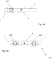
- Fig. 1a is a schematic illustration of a MEMS-based particle manipulation system using lithographically formed microfluidic channels.
- One microfluidic channel 1 may be an input channel which directs a fluid flow.
- the fluid stream in microfluidic channel 1 flows through a first laser interrogation region 101.
- light from one or more lasers is directed.
- the light may be focused to a spot and onto the particles flowing in the stream, wherein the laser interrogation region 101 is disposed upstream of a microfabricated manipulation stage 4.
- the particles have the appropriate fluorescent tag affixed thereto, the tag may be excited and emit a characteristic fluorescent photon. This photon may be detected by optical detectors and evaluated by appropriate logic circuits.
- the logic circuits may control the manipulation stage 4, which may manipulate the tagged particles under the control of the logic circuits.
- the MEMS device may apply a charge to the target particle.
- the manipulation stage 4 may be an actuator, which diverts the target particle into a different flow path as the non-target particles.
- the MEMS actuator may divert the incoming fluid stream into one of the plurality of exit channels, for example into either channel 2 or channel 3. For example, if a signal from laser interrogation region 101 indicates that a target particle is present, the logic circuit coupled to laser interrogation region 101 may send a signal to the MEMS actuator 4 to activate the flap. Drawing down the flap will divert the detected target particle into the sort channel 2 rather than allowing it to flow past into waste channel 3.
- waste channel 3 may also be equipped with an additional laser interrogation region 301.
- This arrangement is shown in Figs. 4a and 4b , which are similar to figs. 3a and 3b , except that two laser interrogation regions 201 and 301 are disposed in sort channel 2 and waste channel 3, respectively.
- the two additional interrogation regions 201 and 301 may measure the increased density of target cells in sort channel 2 compared to waste channel 3, and thus may provide evidence of the effectiveness and accuracy of the MEMS sorter 4 and laser interrogation region 101.
- the additional laser interrogation regions 201 and 301 may act as a cytometer or as a quality control measure.
- the system 10 may give feedback as to the correct setting of any adjustable parameters in the sorting algorithm.
- Such parameters may include, for example, fluorescent pulse shape, width, magnitude or duration, laser intensity, optical alignment or focusing. These parameters may then be adjusted during the sort, rather than waiting for the entire sample to be processed before finding a problem in the sorting.
- the presence of additional laser interrogation regions 201 and/or 301 may provide cytometer capability to the sorter, in that it is able to count, enumerate, or quantify the density or purity of the sorted sample, while the sorting process is underway. This capability may allow the sort process to be adjusted in real time, that is, while it is underway. This may allow an optimization of sort parameters without performing multiple sorting operations on a sample, thus saving time and sample volume.
- Fig. 5 Also shown in Fig. 5 is the field of view 200 of the detector monitoring laser interrogation region 101 as well as additional laser interrogation regions 201 and 301. As indicated in Fig. 5 , all laser interrogation regions may fall within the detector field of view, and thus may share at least a portion of the optical and electronic data detection channel. Accordingly, light collected from the at least one additional laser interrogation region is collected by an optical system which also collects light from the first laser interrogation region. Details as to how to exploit or implement this feature are set forth below with respect to the remaining figures.
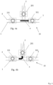
- Figs. 6 and 7 illustrate one exemplary embodiment of a particle manipulation stage.
- the manipulation may be a cell sorting stage 100, 100' that separates at least one target particle flowing in a sample stream of target particles and non-target material. It should be understood that this embodiment is exemplary only, and that many other sorts of particle manipulations may be envisioned, including but not restricted to the particle manipulations described in detail below.
- a magnetically permeable material should be understood to mean any material which is capable of supporting the formation of a magnetic field within itself.
- the permeability of a material is the degree of magnetization that the material obtains in response to an applied magnetic field.
- An external source of magnetic field lines of flux may be provided outside the device 100, as shown in Fig. 7 .
- This source may be an electromagnet 500.
- the electromagnet 500 may include a permeable core 512 around which a conductor 514 is wound.
- the wound conductor or coil 514 and core 512 generate a magnetic field which exits the pole of the magnet, diverges, and returns to the opposite pole, as is well known from electromagnetism. Accordingly, the movable member 110 is generally drawn toward the pole of the electromagnet 500 as shown in Fig. 7 .
- stationary permeable feature 130 should be understood to mean a feature which is affixed to the substrate and does not move relative to the substrate, unlike movable member or valve 110.
- a stationary permeable feature 130 may be shaped to collect these diverging lines of flux and refocus them in an area directly adjacent to the movable member 110 with inlaid permeable material.
- the stationary permeable feature may have an expansive region 132 with a narrower throat 134. The lines of flux are collected in the expansive region 132 and focused into and out of the narrow throat area 134. Accordingly, the density of flux lines in the throat area 134 is substantially higher than it would be in the absence of the stationary permeable feature 130.
- the permeable portion 116 of the movable member 110 is drawn toward the throat 134, thus moving the movable member 110 and diverting surface 112 such that the inlet stream in inlet channel 120 is redirected to the output or sort channel 122. This position is shown in Fig. 7 .
- the particle sorting device is capable of sorting particles at rates in excess of 50 kHz or higher, assuming 10 microseconds required to pull the actuator in, and 10 microseconds required to return it to the as-manufactured position.
- Fig. 9 is a schematic view of the particle manipulation system 400 with camera confirmation in operation.
- the particle manipulation system 400 with camera confirmation may have one or more target particles 150 flowing in the sample stream in the input channel 120 and through the laser interrogation region 101.
- the laser will irradiate the target particle 150 which will then fluoresce as a result of the irradiation.
- the fluorescence will be detected by detector which is not shown in Fig. 10 .
- the output of this detector may be delivered to a controller 1900 ( Fig. 10 , 18 ).
- This controller then may send out a sort trigger pulse which may cause the movable member 110 of the microfabricated particle manipulation stage 100 to move to the sort position as was shown in Fig. 7 .
- the optical camera 160 may be configured to generate repeated images of the same field view as triggered by the controller signal just described. These images may be overlaid to show the sequence and time evolution of the field of view of the optical camera 160. Accordingly, as multiple target particles are sorted by particle manipulation stage 100, this plurality of target particles will show appear in the field of view of the optical camera 160. Thus, the output of the optical camera 160 may show multiple particles within the image, and the particles may be clustered in a particular location within the image. The location of this cluster of target particles may be an indication of the relative precision of the timing of the sort pulse relative to detection of fluorescence of the target particle 150 in the detection region 101. The distribution of particles in the channel may be indicative of the variability of particle speed and location, within the flow, or variability in the fluid flow itself, for example.
- the geometric center of the cluster is referred to herein as the "locus" of particles within the field of view.
- the locus may alternatively be understood as the center of the circle which includes most or all of the detected and sorted particles. If the locus appears in the downstream edge of the field of view of optical camera 160, it may be an indication that the sort trigger is somewhat late. In other words, the position of the locus may be an indication that the timing between the detection of the particles by the laser interrogation region 101, and the opening of the sort gate 110, maybe slightly too early or slightly too late. Accordingly, by analyzing the locus of the target particles in the field of view of the optical him a 160, the timing between the detection and sorting operations may be optimized.
- the particle manipulation system with optical confirmation may be capable of optimizing itself under computer control, that is the system maybe "self-aware". With no other operator intervention, the system may be able to optimize its various parameters including sort gate timing, sort gate width, laser power and positioning, etc., based on the sequence of images captured by the optical camera and analyzed by the computer.
- the particle manipulation system may use a camera to image the target particles and a controller to determine the locus of the particles within a field of view of the camera, and the controller may adjust sort gate timing thereby.
- This feedback loop is shown qualitatively and Fig. 11 as the arrows connecting the optical camera 160 to the controller 1900, and the controller 1900 to the movable member 110.
- the controller 1900 may alter the pulse timing between the detection of the target particle, and the generation of the sort trigger pulse.
- the situation is shown qualitatively in Fig. 13 .
- the microfabricated particle manipulation device may be coupled to a microfabricated fluidic focusing element 300.
- the focusing element 300 may include at least one additional sheath fluid inlet channel 320 that provides a sheath fluid to the sample stream and also a z-focusing curve 330 coupled to the sheath fluid inlet channel 320.
- the sheath fluid may be used to adjust the concentration or positioning of the target particles within the sample inlet channel.
- the focusing element 300 may be configured to urge the target particles into a particular portion of the sample inlet channel 120, such that the sorting process has fewer errors, as described further below.
- Fig. 13 depicts the microfabricated focusing element 300 which may be used to focus the particles in a certain area within the fluid stream.
- the sheath fluid inlet channel 320 adds a sheath fluid to the sample stream, which is a buffering fluid which tends to dilute the flow of particles in the stream and locate them in a particular portion of the stream.
- the combined fluid then flows around a focusing element 300 coupled to the sample inlet channel 120.
- the focusing element 300 may include here a z-focusing curve 330, which tends to herd the particles into a particular plane within the flow. This plane is substantially in the plane of the paper of Fig. 13 .
- the combined fluid in the focusing element 300 then passes another intersection point, a "y-intersection point" 350, which introduces additional sheath fluid above and below the plane of particles.
- a "y-intersection point" 350 which introduces additional sheath fluid above and below the plane of particles.
- two flows may join the z-focus channel 330 from substantially antiparallel directions, and orthogonal to the z-focus channel 330.
- This intersection may compress the plane of particles into a single point, substantially in the center of the stream.
- the target particles may be compressed from a plane to a stream line near the center of the z-focus channel 330 and sample inlet channel 120. Focusing the particles into a certain volume tends to decrease the uncertainly in their location, and thus the uncertainty in the timing of the opening and closing of the movable member or valve 110. Such hydrodynamic focusing may therefore improve the speed and/or accuracy of the sorting operation.
- the angular sweep of z-bend 330 is a curved arc of about 180 degrees. That is, the approximate angular sweep between the junction of the sheath fluid inlet channel 320 and the y-intersection point 350, may be about 180 degrees.
- the radius of curvature of the z-bend 330 may be at least about 100 microns and less than about 500 microns, and the characteristic dimension, that is the width, of the channels is typically about 50 microns to provide the focusing effect.
- the radius of curvature of the channel may be about 250 microns, and the channel widths, or characteristic dimensions, for the sample inlet channel 120 and z-bend channel 330 are on the order of about 50 microns. These characteristic dimensions may provide a curvature sufficient to focus the particles, such that they tend to be confined to the plane of the paper upon exit from the z-focus channel 330 at y-intersection point 350. This plane is then compressed to a point in the channel at the y-intersection point 350. Accordingly, the y-intersection 350 flows along with the z-focusing element 330 may urge the particles into a single stream line near the center of the microfabricated sample inlet channel 120.
- Fig. 13 shows another embodiment of a focusing element, 700.
- the focusing element 700 includes a plurality of segments having a variable lateral dimension or cross section.
- the variable cross section portion of the channel serves to urge or focus the particles into a particular portion of the stream flowing in the channel.
- the novel flow channel may possess portions of variable cross section, wherein the variable cross section arises from the shapes of the sidewalls of the flow channel.
- These variable portions may have one sidewall which is substantially straight with respect to the flow direction, and an adjacent side wall which is not straight, or at least not parallel to the substantially straight portion.
- this adjacent sidewall may be triangular or parabolic in shape, deviating away from the straight sidewall in an expanding region, to a point of maximum channel width, before coming back to the nominal distance between the sidewalls in a contracting region.
- the expanding portion, maximum point, and contracting portion may constitute what is hereafter referred to as a fluid "cavity" 620 in the microfabricated channel.
- the variable channel width segments may define expansion/contraction cavities 620, 620' within the microfluidic channel, wherein the cavity is defined by the expanding portion followed by the contracting portion.
- the cavity 720 should be understood to be in fluid communication with the microfabricated fluid channel, such as sample inlet channel 120, such that fluid flows into and out of the cavity 620. It should be understood that this cavity 620 may be a two-dimensional widening of the channel in the expanding region, and narrowing of the channel in the contracting region. This shape of geometry is shown schematically in Fig. 13 .
- Figs. 14-17 depict another exemplary embodiment of the focusing structure which focuses the suspended particles into a portion, for example a particular quadrant, of the cross section of the fluid channel.
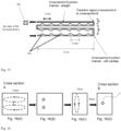
- Fig. 14 is a simplified schematic diagram of a fluid path with a variable cross-section.
- the shaped cavities 720 which are shown in Fig. 14 , have a triangular shape 720 as shown in Fig. 14 . Because of the asymmetry of this triangular shape, these cavities may cause a more effective focusing forces that concentrate particles within the flow.
- the triangular cavity 720 may have a 60° angle with respect to the incoming streamline, and a 30° angle with respect to the outgoing streamline. These angles are as defined in Fig. 14 , which shows that the first-encountered wall 725 may form an angle of about 60 degrees with respect to the parallel, horizontal wall of the flow channel. The second-encountered wall 727 may form an angle of about 30 degrees with respect to the parallel, horizontal wall of the flow channel. The third angle in the triangle is, of course, 90°.
- the relatively wide entrance angle to the triangular region 720 may enforce pronounced Dean flow forces in this region, focusing particles as described above.
- the gentler 30 degree exit angle may urge the particles into their new stable positions.
- the series of triangular regions 720 may enforce this behavior again and again, until the stable positions shown in Fig. 16B are reached.
- the pitch between the triangular cavities may be about 2 mm.
- the height of each triangular cavity as defined in Fig. 14 maybe about 360 ⁇ m.
- the total length of the triangular cavity may be on the order of about 1000 ⁇ m, or 1 mm. It should be understood that these dimensions are exemplary only.
- the incoming fluid channel may have a channel height of about 110 ⁇ m, as shown in the figure.
- the depth of this channel may be about 80 ⁇ m. This channel cross-section is maintained throughout the input to the triangle. Upon encountering the triangular cavity 760, the 110 micron dimension expands dramatically, whereas the 80 micron depth is maintained, as further described below.
- the 80 ⁇ m dimension may pertain to the depth of the channel, that is, the depth of the channel in the dimension into the paper.
- a perspective view of the flow channel also appears in Fig. 14 .
- This 80 ⁇ m depth is maintained throughout the triangular cavity.
- the 110 ⁇ m channel height varies from 110 ⁇ m at the entrance to a height of (360+110) ⁇ m at the apex of the triangular cavity 760, before descending again to 110 ⁇ m at the output of the triangular cavity 760.
- the curvature imparted to the streamlines by the existence of this cavity generates the Dean flow which provides the focusing force as described previously.
- Fig. 15 is a simplified schematic illustration of the flow channel from a zoomed out perspective.
- Fig. 15 shows a plurality of triangular cavities disposed in the fluid path. It should be understood, that this diagram is not to scale, and the details may be altered for ease of illustration. In particular whereas Fig. 15 shows only about 18 triangles cavities, there may in fact be many more, for example 50 or even 75 triangular cavities in the flow path.
- Fig. 14 There may also be a transition region shown in Fig. 14 , wherein the shape of the flow channel changes abruptly.
- the cross sectional shape of the flow channel may transition from shape "A" to shape "B".
- the channel height may bt, for example, between 50um and 500 um
- the channel width may be between about 30 um and about 120 um.
- the aspect ratio in the "tall" segment (AR>1) may simply have an aspect ratio greater than 1 (for example, between 1+ and 50), and the aspect ratio in the "wide” segment may simply have an aspect ratio less than 1 (for example, between 0.4 and 1-).
- the total path length may be on the order of, for example, 8 cm or more. In view of this length, it may be advantageous to fold the fluid path in order to make the device more compact.
- Fig. 15 shows six such turns, which gives a fluid path a serpentine shape. It should be understood that the path may be much longer with more turns. However, the features may not be drawn to scale because the details are impossible to render on the much larger scale of this 8 cm fluid path. Over this 8 cm distance, the particles in the fluid stream may be strongly focused into a single quadrant of the cross section. The location of the microfabricated fluid valve 100 is shown schematically in Fig. 15 , but again, the details of the valve 100 are not rendered.
- a relatively large number of triangular cavities 760 is used, each having a shape general as depicted in Fig. 14 .
- 30-70 cavities are used, or more specifically on the order of 50 triangular cavities 760 may be used.
- the total channel length may be about 8-10 cm long.
- the features depicted in Fig. 14 are not to scale.
- the triangular cavities 760 are smaller and more numerous than shown in Fig. 14 , but for clarity of depiction and to keep the size of the drawing manageable, they are presented as shown in Fig. 14 .
- This length of fluid path will result in a focusing of the particles in a particular portion of the fluid channel.
- the particles may be arranged in two points along the depth dimension. That is, across the 80 ⁇ m depths of this flow channel there may exist to concentrated areas where the target particles are urged. This behavior is driven by the Dean flow forces existing in the curved channel with the aspect ratio being greater than one. If this aspect ratio is suddenly changed to a value less than one, the effect will be to urge the target particles into two new, and different paths plus spots with respect to the short dimension of the aspect ratio short dimension of the channel.
- Fig. 16 Also illustrated in Fig. 16 is the effect of a sudden change in the aspect ratio, in particular an aspect ratio less than one, such that the channel is deeper than it is tall.
- the aspect ratio in particular an aspect ratio less than one
- the cross-section B what was the long dimension 110 is altered to become the short dimension 50 ⁇ m.
- the aspect ratio of this cross-sectional channel B is now less than one.
- the particles are urged again into a two spots along the short dimension of the flow channel, which is now the height dimension, 50 microns. Or in other words, the particles tend to be focused in two spots along the long dimension, which is now the depth dimension 80 microns.
- the effect of this change is therefore to suppress the second stable position that was formed in the AR>1 channel. That is, the AR>1 channel tends to focus particles on the right hand side of the channel, but the transition to cross section B suppresses the second stable position and encourage all the particle to flow in a single location of the right hand side of the channel.
- This effect is illustrated in Fig. 16A-D where one of the two stable positions is effectively eliminated. Accordingly, the two stable previously focused regions shown in Fig. 16 may be collapsed into one focal region located within a portion of the cross section of the particle focusing channel.
- the effect is to undermine or suppress one of the stable positions of the particles as illustrated in Fig. 16B , Fig. 16C and Fig. 16D.
- the lone of the two loci of particles is effectively suppressed, leading only one locus in the flow channel, that being on the right side of the short dimension of the channel as illustrated in Fig. 16D.
- Fig. 16C and Fig. 16D show the flows and the remaining focal spot within the cross section.
- FIG. 17 Another way to shift the locations of the stable position within the flow channel, is to impose a 90° turn in the fluid path. This may provide an effect similar to the change in aspect ratio from AR>1 to AR ⁇ 1, but in the orthogonal dimension. As such, the effect is difficult to render in a 2-dimensional drawing. Nonetheless, the novel flow path is depicted in Fig. 17 . It should be understood that the dashed portions of the flow pass shown in Fig. 17 may lie under, over, or adjacent to their projection of the solid lines shown in Fig. 17 .
- the detector may be, for example, a photomultiplier tube (PMT) which creates a cascade of charges when a photon strikes the detector surface. Weak signals, for example a single photon, may be detected by these sensitive devices. However, for stronger fluorescent signals, the cascade may saturate, limiting the dynamic range and thus reducing the quality of the information collected by the detector.
- PMT photomultiplier tube
- the invention applies to flow cytometry and to automatically adjust the sensor gain during the measurement of each particle. Downstream processing will combine the signal from the detector with the gain setting that was used for each instant of time to generate a high dynamic range output signal. This technique eliminates the manual gain adjustment and effectively increases the dynamic range of the sensor so that a larger range of light levels can be measured.
- a difference between adjusting "sensor” gain and “detector” gain may be that the former may be done via the bias voltage, whereas the latter can be done also in the amplifier or digitally.
- the system and circuit described below may provide a high resolution, wide dynamic range optical detector when using a high sample rate Analog to Digital Converter (ADC).
- ADC Analog to Digital Converter
- the detection platform does not require special front-end optics or multiple optical sensors in order to achieve a high dynamic range.
- the resulting dynamic range will be higher than the optical sensor can deliver when using a fixed gain.
- This platform generates a high speed gain modulation signal which is synchronized to the clock used for the ADC.
- the gain modulation signal is 50% of the frequency of the ADC clock, and is phase-locked to the ADC clock. The phase between these signals is adjusted such that every other sample from the ADC will be measuring the response of the detector when it is using the high gain setting, and every other sample will be measuring the response of the detector when it is using the low gain setting.
- the signal processing system separates the high gain and low gain digital sample streams and performs digital signal processing (DSP) on these streams.
- DSP digital signal processing
- the conditioned streams are then scaled and recombined into a single, high resolution, wide dynamic range stream.
- the optical sensor and amplification electronics are able to respond properly to the high frequency gain control signal.
- the signal processing can be tuned to the sensor and amplifier electronics in order to generate an accurate output stream.
- the sensor gain may be switched between more than two discrete gain levels.
- the sensor gain is adjusted continuously between two gain levels using a predetermined sequence or pattern.
- a simple example would be a sine wave at a fixed frequency. Because the pattern of the gain control signal is known, the downstream electronics can use timing to determine the precise gain setting that was used for each instant of time.
- the sensor gain is adjusted continuously to keep the output signal within the range of the measurable levels of the downstream electronics.
- Automatic gain control Commonly called automatic gain control.
- the downstream processing may combine the precise gain setting with the output signal of the detector for each instant of time.
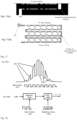
- Figs. 18 and 19 describe such a system, wherein the sensor gain on the detector is changed dynamically by a circuit including, in some embodiments, a gain changer or gain modulator, an ADC and a signal processing circuit that demultiplexes and then applies a suitable gain to the higher and the lower sample streams, independently.
- the sampler streams may then be recombined.
- Fig. 18 a is a simplified schematic illustration of a manner for implementing a gain change function on the florescence detector, here a photomultiplier tube (PMT).
- the gain on the sensor may be modulated, toggled, or varied between a higher value and a lower value by a gain controller 1610. This will result in a signal which varies or is modulated between a higher value 1601 and a lower value 1602.
- portions of the plot labeled with reference number 1601 correspond to the signal amplitude when the gain is at the first higher value, i.e. a higher gain is applied to the signal.
- the modulation may be characterized by an amplitude and a frequency f.
- Reference number 1602 indicates the portions of the signal curve where the gain is set to the lower value, i.e. less gain is applied to the signal. The amplitude of the signal thus cycles back and forth between two levels, a higher level 1601 and a lower level 1602.
- This variable signal can then be sampled using a clock phase-locked to the gain changing frequency.
- the frequency of the sampling clock may be 2f, whereas the modulation frequency is f.
- the sample stream from the sampling circuit may then consist of a sequence of values at the higher level 1601, interleaved with a sequence of values at the lower level 1602.
- the phase locked sample stream may then be sent to an ADC 1605, as shown in Fig. 18(B).
- the sampling clock and ADC 1605 may be synchronized with the gain controller 1610 of detector, such that the analog to digital converter samples first a high value, 1601, followed be a lower value 1602.
- the data coming from the ADC 1605 may consist of a sequence of interleaved higher and lower digitized numbers.
- the output of the analog to digital converter may then be provided to a splitter, 1620 or demultiplexer, as shown in Fig. 19 .
- the purpose of the splitter divides the higher gain elements, and the lower gain elements, into two different data streams.
- the upper path in Fig. 19 corresponds to the higher amplitude samples 1601 and the lower path corresponds to the lower amplitude samples 1602.
- These two pulse trains may be applied to digital signal processors 1630 and 1630' respectively.
- the DSP may provide whetever additional signal conditioning may be desired.
- a scaling circuit 1640, 1640' may then provide a final opportunity to adjust the magnitude or amplitude of the data, or other attributes.
- the signals may then be recombined by a combiner or multiplexer 1650.
- the excitation laser described previously can be modulated instead of the gain of the detector. This accomplishes the same thing.
- a single laser may be modulated between a higher and lower power setting.
- two lasers may be used, one at higher power that is turned on/off at high speed, and one lower power laser that is continuously on. This low power laser can be very inexpensive.
- Another alternative is to provide an external variable optical attenuator (VOA) on the output of the laser.
- VOA variable optical attenuator
- Machine learning and artificial intelligence techniques as described above may also be applied to the variable gain controller 1610 and the sampling clock 1615, to fine tune their performance with respect to the control variables and performance metrics.
- Figs. 20-23 illustrate another embodiment of the invention, wherein, the sensors of the detector are controlled individually and/or independently, and according to an expected magnitude of the signal they are expected to receive.
- the expected signal levels may be based on previous detection, or on geometry of the optical arrangement, or on a monitor detector, for example.
- Fig. 23 Shows another embodiment in which a plurality of beams, each covering a different spectral region, is projected onto an advantageous configuration of arrays of sensors.
- the beams may originate from the same or different interrogation regions, or from different wavelength ranges of emitted light from the same sample.
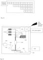
- Another module, 1680 may perform the gain modulation, ADC, and DSP functions described above with respect to Figs. 18 and 19 .
- the embodiment shown in Fig. 24 may be based on a FACS-type detection mechanism, wherein one or more lasers 1400 impinges on the sample inlet channel 120 as described above.
- the relative amount of light may be monitored by a computer 1900.
- the computer 1900 may then generate a control signal that controls the force-generating means or electromagnet 500.
- the controller 1900 may output a sort trigger that causes the electromagnet 500 to be energized, thus moving the movable member 110 into the sort position shown in Fig. 7 .
- the movable member thus diverts the target particle from the input channel 120 into the sort channel 122 rather than the waste channel 140. This is normal operation of the microfabrication particle sorting system 1000.
- the controller 1900 may generate a camera trigger (as well as a sort trigger) based on the detection of this fluorescence signal.
- the other optical components in particle manipulation system 1000 may include a beamsplitter 1500 and multiple color detectors 1300.
- the beam splitter1500 may reflect the incoming light from laser 1400 onto the MEMS manipulation device 100.
- the output of detectors 1300 may be analyzed by the controller 1900 and compared to a threshold in normal operation.
- the controller 1900 may be understood to be operating in conjunction with the deep learning module 1950 described above, where in the deep learning module may include an annotated image library 1960 and a classifier 1970 and an analyzer 1980.
- the particle manipulation system may include a particle manipulation stage and a sample stream in a microfluidic inlet channel, an optical interrogation device upstream of the particle manipulation stage which identifies target particles, and an optical confirmation device downstream of the particle manipulation stage, wherein the optical confirmation device uses a camera to determine the presence or absence of a target particle.
- the MEMS particle manipulation system 1000 may be used in conjunction with one or more additional downstream cameras 160, wherein the additional cameras are used to confirm the effectiveness or accuracy of a manipulation stage in manipulating a stream of particles.
- the downstream evaluation by camera may occur beyond the sorting stage 100 or 100' and may allow the operator to measure one event number (e.g. the captured event rate post-sort) divided by another event number (e.g. the initial event rate pre-sort) for individual particle types, and to feedback to adjust initial interrogation parameters (e.g. such as x, y, z position and also "open window" length in time) based on this ratio. This method may thus be used to optimize the yield or accuracy of the system 1000.
- event number e.g. the captured event rate post-sort
- another event number e.g. the initial event rate pre-sort
- initial interrogation parameters e.g. such as x, y, z position and also "open window" length in time
- the operator could measure the event rate post-sort of target cells, divided by total event rate post-sort feedback to adjust initial laser interrogation parameters such as x, y, z position and also "open window" length in time, in order to optimize the purity of the sorting system 1000.
- These sorting parameters may be adjusted by changing control signal 2000 which is sent by computer 1900 to electromagnet 500, or by changing the optical detection parameters or by changing the laser control signals, as shown in Fig. 24 .
- the camera system 1600 may be used in conjunction with controller 1900 to improve or optimize the performance of the system with respect to at least one measured parameter.
- the particle manipulation system may image the target particles with the camera, determine the locus of the particles within a field of view of the camera with a controller, and adjust a sorting parameter.
- the system may optionally be used with machine learning or artificial intelligence techniques to choose superior sorting parameters.
- One such sorting parameter is the timing of the sort gate, but other parameters may include at least one of laser fluorescent pulse shape, width, magnitude or duration, laser intensity, optical alignment or focusing, gate duration, and so forth. These parameters may be optimized with respect to purity, yield, or some other measured output of the system 1000.
- the particle manipulation system described above may make use of any of a number of particle manipulations. These manipulations may include moving the particles using a pressure pulse, so as to guide them in a particular direction. Other manipulations may include washing, mechanical interference such as pushing or squeezing, application of heat, cooling, application of fields such as magnetic or electric fields. This field-based manipulation may result in electroporesis, transfection, or electrophoresis which may alter the trajectory of the particles. More broadly, the particle manipulation system may be combined with transfection of wide-ranging sorts and methodologies.
- the system 1000 may include internet capability, remote operation and remote data storage.
- the required connections to the internet, cloud, or data repository 5000 may be hardwired or wireless, and may allow non-local operation by a remote operator 4000.
- the manipulations may include, for example, mechanical probing, squeezing, slicing, rupturing.
- Other embodiments may use heating, tagging, sorting, imaging, counting.
- the particle may be focused into a particular streamline, which may improve performance of the system.
- the particle manipulation system 1000 may be coupled to a fluidic focusing structure as described above, which tends to concentrate the particles in a particular portion of the microfabricated channel.
- the fluidic focusing system may include the three-dimensional focusing channel described above, which may focus the ensemble of particle into stream lines near the center of the channel.
- the particle manipulation system 1000 may be coupled to a droplet generator which generates droplets containing one or more known, identified particles. These droplets may optionally be dispensed into an immiscible fluid, such as water droplets into a hydrophobic fat or an oil. These particles may be brought into the droplet or sequence of droplets in a particular desired order, under computer control, by proper manipulation of the system.
- the target particles may also be coupled to a bar coded bead which identifies uniquely the bead/particle combination, and thus identifies uniquely the bound particle.
- the particle manipulation system 1000 may be coupled to a genetic sequencer, that may sequence the DNA or RNA of the particles enclosed in the droplet.
- the particle manipulation system 1000 may be combined with a device that can activate a particular bioactive compound, for example a protein.
- the protein may be activated optically (photoactivation) or chemically, for example.
- the activated compound may then interact with the manipulated particle.
- the particle manipulation system 1000 may be combined with a selective lysis system.
- the manipulated particles may be lysed on demand, and only particular cells subjected to the lysing.
- the lysant may be photoactivated.
- the particle manipulation system 1000 may be combined with a selective optical activation system, for example a selectable UV light source.
- the UV light may photoactivate a bleaching/quenching system, wherein the UV light is applied to a fluorophore to quench the fluorescence.
- This system may use the above described hardware and software system to apply the photoactivation to only a subset of targeted particles.
- a measurement (of a control variable) is made using a sensor, and this measurement may form the basis of a feedback system wherein a manipulation parameter is adjusted based on the value of the measurement (of the control variable), and the measurement is taken again after the adjustment.
- the "manipulation parameters" may be those variables used by the control loop to alter the performance of the manipulation system in some way. Accordingly, the feedback loop may be used to drive the measurement of this control variable to a predefined level, using the manipulation parameters.
- control variables may include Hall effect detection, fluorescence intensity, scatter, side scatter, locus of particle detected, statistics as to the relative location of particles in the channel. Additionally, capacitive measurements may be used to detect the passage of the target particle within the channel. Other indicators may include the deflection of an mechanical device, sensor or actuator. Accordingly, the control variable may be, for example, fluorescence, capacitance, mechanical or spectroscopic data, the number of live or dead cells passing through the device, or their ratio.
- the feedback loop may be operable to improve or maximize an aspect of the manipulated population, such as their purity or yield, ratio of live to dead.
- FTIR Fourier-transform infrared
- FTIR is a technique used to obtain an infrared spectrum of absorption or emission of a solid, liquid or gas.
- An FTIR spectrometer simultaneously collects high-resolution spectral data over a wide spectral range.
- manipulation parameters may include timing of a gate for a sorter, duration of the gate signal, waveform of the valve timing signal.
- Other manipulation parameters may include fluid velocity, fluid pressure, particle concentration.
- the feedback loop may attempt to improve or maximize the tightness of distribution of the particles in the channel, and the location of their locus.
- the parameters that may be adjusted based on the measurements may be valve timing, sort gate, flow rate, viscosity, laser algorithms, and adjusting the timing of the leading and/or trailing edges of the valve gate signal.
- the particle manipulation system may be coupled with a cell counter/analyzer or cytometer, such as the MACS Quant, developed and manufactured by Miltenyi Biotec B.V. & Co. KG.
- the cytometer may provide valuable analytical information such as particle size and distribution, wherein this information is then shared with the particle manipulation system to further optimize the manipulation in terms of target particle and cell populations.
- the cytometer may alternatively by disposed downstream of the particle manipulation system, in order to gather information or statistics as to the performance of the particle manipulation system.
- the cytometer may assess the sort purity or yield, for example.
- the particle manipulation system 1000 may be coupled to a particle sorting system.
- the particle sorting system can be configured to perform a pre-sort or debulking, to remove a large number of non-target species, before routing the sorted stream to the particle manipulation system.
- a magnetic bead cell separation for example using Miltenyi Biotec B.V. & Co. KG MACSiMag, may do a pre-sort/debulking to reduce the concentration of cells in a sample.
- a cell handling system such as the Miltenyi Biotec B. V. & Co. KG CliniMACS Prodigy may be used to increase automation and reduce handling of the fluids and samples, for example.
- the particle manipulation system 1000 may be operated in conjunction with a cloud computing system, wherein operational software is downloaded from the cloud, and the results of the procedure may be uploaded. After downloading an algorithm with control parameters and target quantities for the feedback loop, the results of the particle manipulation may then be uploaded to the cloud for remote evaluation.
- the cloud may serve as a repository of data for manipulations occurring in different geographic locations, such that results may be quickly and easily compared.
- the particle manipulation system 1000 may be coupled to a robotically controlled automation system.
- the system may perform the manipulations of fluids such as buffers, reagents and lysants, to name just a few.
- fluids such as buffers, reagents and lysants
- a plurality of fluid receptacle such as multiwell titer plates
- large scale parallel operations can be performed, greatly improving throughout and efficiency.
- Very few human operators would be needed to oversee the operations, and the oversight could b done remotely, increasing the overall safety of the system.
- remote operation could be easily combined with robotic control over the system, cloud-housed software and global data repositories.
- the particle manipulation system 1000 can be implemented on manufacturing lines, such as cell manufacturing lines, and can thus serve as quality control devices, to maintain the integrity of the manufacturing process. Any deviation from expected values, for example, purity, yield and viability, could prompt the interruption of the manufacturing process for failure analysis to take place. Again, this can all be done remotely.
- the particle manipulation system may be combined with PCR testing to amply the effluent or to confirm the identity of the pathogen.
- the algorithm could be self-correcting, that is, under feedback control, for a largely completely automated process. Combined with robotically controlled tasks such as the movement of fluids, the entire process may be possible with little or no human intervention.
- the system can adaptively respond to events occurring, such as an unexpected change in pressure or flow, indicating that a clog is forming in a channel.
- the detector used in the system may have variable gain applied electronically in response to variable signal levels.
- the pixels or sensors of the detector may be controlled independently to adjust the gain to expected levels of input.
- the fluorescent signal may be separated spectrally by a wavelength separating device.
- the wavelength separating device may form a spatial intensity profile on a first spatial axis.
- the variable gain detector may also have a sampling circuit that samples the higher value and the lower value, and digitizes these samples.
- the wavelength separating may be implemented using refractive or diffractive optics, a graded optical filter, filters of different attenuations.
- the intensity profile may be projected onto on or more of the plurality of detectors, wherein the same or different light intensities are incident onto the plurality of independently controllable sensors.
- the independently controllable sensors may be programmable, or even remotely programmable.
- the independently controllable detectors may be arranged to detect four spectrally dispersed wavelengths.
Landscapes
- Chemical & Material Sciences (AREA)
- Health & Medical Sciences (AREA)
- Dispersion Chemistry (AREA)
- Analytical Chemistry (AREA)
- General Health & Medical Sciences (AREA)
- Life Sciences & Earth Sciences (AREA)
- Physics & Mathematics (AREA)
- Biochemistry (AREA)
- General Physics & Mathematics (AREA)
- Immunology (AREA)
- Pathology (AREA)
- Clinical Laboratory Science (AREA)
- Chemical Kinetics & Catalysis (AREA)
- Hematology (AREA)
- Investigating, Analyzing Materials By Fluorescence Or Luminescence (AREA)
Priority Applications (1)
| Application Number | Priority Date | Filing Date | Title |
|---|---|---|---|
| EP23198689.4A EP4528248A1 (de) | 2023-09-21 | 2023-09-21 | Teilchenmanipulationssystem mit zytometrischer fähigkeit und rückkopplungsschleife und detektor mit variabler verstärkung |
Applications Claiming Priority (1)
| Application Number | Priority Date | Filing Date | Title |
|---|---|---|---|
| EP23198689.4A EP4528248A1 (de) | 2023-09-21 | 2023-09-21 | Teilchenmanipulationssystem mit zytometrischer fähigkeit und rückkopplungsschleife und detektor mit variabler verstärkung |
Publications (1)
| Publication Number | Publication Date |
|---|---|
| EP4528248A1 true EP4528248A1 (de) | 2025-03-26 |
Family
ID=88146869
Family Applications (1)
| Application Number | Title | Priority Date | Filing Date |
|---|---|---|---|
| EP23198689.4A Pending EP4528248A1 (de) | 2023-09-21 | 2023-09-21 | Teilchenmanipulationssystem mit zytometrischer fähigkeit und rückkopplungsschleife und detektor mit variabler verstärkung |
Country Status (1)
| Country | Link |
|---|---|
| EP (1) | EP4528248A1 (de) |
Citations (5)
| Publication number | Priority date | Publication date | Assignee | Title |
|---|---|---|---|---|
| US6838056B2 (en) | 2002-07-08 | 2005-01-04 | Innovative Micro Technology | Method and apparatus for sorting biological cells with a MEMS device |
| US7220594B2 (en) | 2002-07-08 | 2007-05-22 | Innovative Micro Technology | Method and apparatus for sorting particles with a MEMS device |
| US7229838B2 (en) | 2002-07-08 | 2007-06-12 | Innovative Micro Technology | MEMS actuator and method of manufacture for MEMS particle sorting device |
| US20210080368A1 (en) * | 2019-09-12 | 2021-03-18 | Cytonome/St, Llc | Systems and methods for extended dynamic range detection of light |
| US20230136744A1 (en) * | 2021-11-04 | 2023-05-04 | Owl biomedical, Inc. | Particle manipulation system with cytometric capability and feedback loop and variable gain detector |
-
2023
- 2023-09-21 EP EP23198689.4A patent/EP4528248A1/de active Pending
Patent Citations (6)
| Publication number | Priority date | Publication date | Assignee | Title |
|---|---|---|---|---|
| US6838056B2 (en) | 2002-07-08 | 2005-01-04 | Innovative Micro Technology | Method and apparatus for sorting biological cells with a MEMS device |
| US7220594B2 (en) | 2002-07-08 | 2007-05-22 | Innovative Micro Technology | Method and apparatus for sorting particles with a MEMS device |
| US7229838B2 (en) | 2002-07-08 | 2007-06-12 | Innovative Micro Technology | MEMS actuator and method of manufacture for MEMS particle sorting device |
| US7264972B2 (en) | 2002-07-08 | 2007-09-04 | Innovative Micro Technology | Method and apparatus for sorting biological cells with a MEMS device |
| US20210080368A1 (en) * | 2019-09-12 | 2021-03-18 | Cytonome/St, Llc | Systems and methods for extended dynamic range detection of light |
| US20230136744A1 (en) * | 2021-11-04 | 2023-05-04 | Owl biomedical, Inc. | Particle manipulation system with cytometric capability and feedback loop and variable gain detector |
Similar Documents
| Publication | Publication Date | Title |
|---|---|---|
| EP2880419B1 (de) | Teilchenmanipulationssystem mit zytometriekapazität | |
| US7767444B2 (en) | Cell analysis using laser with external cavity | |
| EP2788737B1 (de) | Analyse und sortierung von im fluss befindlichen biologischen zellen | |
| US11371927B2 (en) | Method and device for optically examining a plurality of microscopic samples | |
| JP6396911B2 (ja) | 粒子を選別するためのシステム、装置、および、方法 | |
| Picot et al. | Flow cytometry: retrospective, fundamentals and recent instrumentation | |
| US9168568B2 (en) | Particle manipulation system with cytometric confirmation | |
| EP2640844B1 (de) | System zum identifizieren und sortieren lebender zellen | |
| JP2008501999A (ja) | 光学流体顕微鏡装置 | |
| US20230136744A1 (en) | Particle manipulation system with cytometric capability and feedback loop and variable gain detector | |
| JP2015072272A (ja) | 面外チャネルを備えた粒子操作システム | |
| US20240272061A1 (en) | Flow Cytometers Including Light Collection Enhancers, And Methods of Using The Same | |
| US12623254B2 (en) | Systems and methods for particle sorting with automated adjustment of operational parameters | |
| US20060177940A1 (en) | Optical trap separations in microfluidic flows | |
| US20240067920A1 (en) | Particle manipulation system with cytometric capability and feedback loop and variable gain detector | |
| US20230118941A1 (en) | Particle manipulation system with cytometric capability and feedback loop | |
| US20230124069A1 (en) | Particle manipulation system with cytometric capability and feedback loop | |
| EP4173706A1 (de) | Partikelmanipulationssystem mit cytometrischer fähigkeit und rückkopplungsschleife | |
| US20240142368A1 (en) | Segmented side fluorescence detector flow cytometry | |
| EP4632350A1 (de) | Quantitative durchflusszytometrie-lichtstreuungsdetektorausrichtung |
Legal Events
| Date | Code | Title | Description |
|---|---|---|---|
| PUAI | Public reference made under article 153(3) epc to a published international application that has entered the european phase |
Free format text: ORIGINAL CODE: 0009012 |
|
| STAA | Information on the status of an ep patent application or granted ep patent |
Free format text: STATUS: THE APPLICATION HAS BEEN PUBLISHED |
|
| AK | Designated contracting states |
Kind code of ref document: A1 Designated state(s): AL AT BE BG CH CY CZ DE DK EE ES FI FR GB GR HR HU IE IS IT LI LT LU LV MC ME MK MT NL NO PL PT RO RS SE SI SK SM TR |
|
| STAA | Information on the status of an ep patent application or granted ep patent |
Free format text: STATUS: REQUEST FOR EXAMINATION WAS MADE |
|
| 17P | Request for examination filed |
Effective date: 20250923 |