EP4528331A1 - Système de détection de bord et procédé de détection d'un bord - Google Patents
Système de détection de bord et procédé de détection d'un bord Download PDFInfo
- Publication number
- EP4528331A1 EP4528331A1 EP23198331.3A EP23198331A EP4528331A1 EP 4528331 A1 EP4528331 A1 EP 4528331A1 EP 23198331 A EP23198331 A EP 23198331A EP 4528331 A1 EP4528331 A1 EP 4528331A1
- Authority
- EP
- European Patent Office
- Prior art keywords
- edge
- detection system
- edge detection
- sensor unit
- distance value
- Prior art date
- Legal status (The legal status is an assumption and is not a legal conclusion. Google has not performed a legal analysis and makes no representation as to the accuracy of the status listed.)
- Pending
Links
Images




Classifications
-
- E—FIXED CONSTRUCTIONS
- E01—CONSTRUCTION OF ROADS, RAILWAYS, OR BRIDGES
- E01C—CONSTRUCTION OF, OR SURFACES FOR, ROADS, SPORTS GROUNDS, OR THE LIKE; MACHINES OR AUXILIARY TOOLS FOR CONSTRUCTION OR REPAIR
- E01C19/00—Machines, tools or auxiliary devices for preparing or distributing paving materials, for working the placed materials, or for forming, consolidating, or finishing the paving
- E01C19/004—Devices for guiding or controlling the machines along a predetermined path
- E01C19/006—Devices for guiding or controlling the machines along a predetermined path by laser or ultrasound
-
- E—FIXED CONSTRUCTIONS
- E01—CONSTRUCTION OF ROADS, RAILWAYS, OR BRIDGES
- E01C—CONSTRUCTION OF, OR SURFACES FOR, ROADS, SPORTS GROUNDS, OR THE LIKE; MACHINES OR AUXILIARY TOOLS FOR CONSTRUCTION OR REPAIR
- E01C23/00—Auxiliary devices or arrangements for constructing, repairing, reconditioning, or taking-up road or like surfaces
- E01C23/01—Devices or auxiliary means for setting-out or checking the configuration of new surfacing, e.g. templates, screed or reference line supports; Applications of apparatus for measuring, indicating, or recording the surface configuration of existing surfacing, e.g. profilographs
-
- E—FIXED CONSTRUCTIONS
- E01—CONSTRUCTION OF ROADS, RAILWAYS, OR BRIDGES
- E01C—CONSTRUCTION OF, OR SURFACES FOR, ROADS, SPORTS GROUNDS, OR THE LIKE; MACHINES OR AUXILIARY TOOLS FOR CONSTRUCTION OR REPAIR
- E01C19/00—Machines, tools or auxiliary devices for preparing or distributing paving materials, for working the placed materials, or for forming, consolidating, or finishing the paving
- E01C19/48—Machines, tools or auxiliary devices for preparing or distributing paving materials, for working the placed materials, or for forming, consolidating, or finishing the paving for laying-down the materials and consolidating them, or finishing the surface, e.g. slip forms therefor, forming kerbs or gutters in a continuous operation in situ
-
- E—FIXED CONSTRUCTIONS
- E01—CONSTRUCTION OF ROADS, RAILWAYS, OR BRIDGES
- E01C—CONSTRUCTION OF, OR SURFACES FOR, ROADS, SPORTS GROUNDS, OR THE LIKE; MACHINES OR AUXILIARY TOOLS FOR CONSTRUCTION OR REPAIR
- E01C19/00—Machines, tools or auxiliary devices for preparing or distributing paving materials, for working the placed materials, or for forming, consolidating, or finishing the paving
- E01C19/48—Machines, tools or auxiliary devices for preparing or distributing paving materials, for working the placed materials, or for forming, consolidating, or finishing the paving for laying-down the materials and consolidating them, or finishing the surface, e.g. slip forms therefor, forming kerbs or gutters in a continuous operation in situ
- E01C19/4866—Machines, tools or auxiliary devices for preparing or distributing paving materials, for working the placed materials, or for forming, consolidating, or finishing the paving for laying-down the materials and consolidating them, or finishing the surface, e.g. slip forms therefor, forming kerbs or gutters in a continuous operation in situ with solely non-vibratory or non-percussive pressing or smoothing means for consolidating or finishing
- E01C19/4873—Apparatus designed for railless operation
-
- G—PHYSICS
- G01—MEASURING; TESTING
- G01S—RADIO DIRECTION-FINDING; RADIO NAVIGATION; DETERMINING DISTANCE OR VELOCITY BY USE OF RADIO WAVES; LOCATING OR PRESENCE-DETECTING BY USE OF THE REFLECTION OR RERADIATION OF RADIO WAVES; ANALOGOUS ARRANGEMENTS USING OTHER WAVES
- G01S17/00—Systems using the reflection or reradiation of electromagnetic waves other than radio waves, e.g. lidar systems
- G01S17/02—Systems using the reflection of electromagnetic waves other than radio waves
- G01S17/06—Systems determining position data of a target
- G01S17/42—Simultaneous measurement of distance and other co-ordinates
-
- G—PHYSICS
- G01—MEASURING; TESTING
- G01S—RADIO DIRECTION-FINDING; RADIO NAVIGATION; DETERMINING DISTANCE OR VELOCITY BY USE OF RADIO WAVES; LOCATING OR PRESENCE-DETECTING BY USE OF THE REFLECTION OR RERADIATION OF RADIO WAVES; ANALOGOUS ARRANGEMENTS USING OTHER WAVES
- G01S17/00—Systems using the reflection or reradiation of electromagnetic waves other than radio waves, e.g. lidar systems
- G01S17/88—Lidar systems specially adapted for specific applications
-
- G—PHYSICS
- G01—MEASURING; TESTING
- G01S—RADIO DIRECTION-FINDING; RADIO NAVIGATION; DETERMINING DISTANCE OR VELOCITY BY USE OF RADIO WAVES; LOCATING OR PRESENCE-DETECTING BY USE OF THE REFLECTION OR RERADIATION OF RADIO WAVES; ANALOGOUS ARRANGEMENTS USING OTHER WAVES
- G01S17/00—Systems using the reflection or reradiation of electromagnetic waves other than radio waves, e.g. lidar systems
- G01S17/88—Lidar systems specially adapted for specific applications
- G01S17/93—Lidar systems specially adapted for specific applications for anti-collision purposes
- G01S17/931—Lidar systems specially adapted for specific applications for anti-collision purposes of land vehicles
-
- E—FIXED CONSTRUCTIONS
- E01—CONSTRUCTION OF ROADS, RAILWAYS, OR BRIDGES
- E01C—CONSTRUCTION OF, OR SURFACES FOR, ROADS, SPORTS GROUNDS, OR THE LIKE; MACHINES OR AUXILIARY TOOLS FOR CONSTRUCTION OR REPAIR
- E01C2301/00—Machine characteristics, parts or accessories not otherwise provided for
- E01C2301/14—Extendable screeds
Definitions
- the invention relates to the detection of edges as a reference for the installation of road surfaces.
- references are used along which the paver finisher, and in particular its screed, can be guided. These references include, for example, wires or edges. Examples of edges used as references are curb edges, edges of previously laid pavement layers, or milled edges created by removing pavement layers to be replaced.
- the guidance of the paver finisher or screed or its extension parts along the reference is often still carried out manually by operating personnel. However, further automation is being sought.
- a challenging task here is to record the course of the reference.
- WO 2020 088 782 A1 A sensor system for a construction machine, in particular a road paver, is known, which includes a laser scanner. This is intended to enable tracking by steering the road paver or extending or retracting extendable screed parts.
- the edge detection system comprises a sensor unit configured to emit laser pulse sequences in a plurality of directions such that the laser pulse sequences are reflected at a plurality of locations on a surface to be scanned.
- the sensor unit is further configured to detect reflections of the laser pulse sequences and, based on the detected reflections, to generate polar coordinate signals representing polar coordinates, wherein the polar coordinates include a distance value and an associated angle value.
- the edge detection system is further configured to transform the polar coordinate signals into Cartesian coordinate signals representing Cartesian coordinates and, based on the Cartesian coordinate signals, to determine a position of an edge in the surface to be scanned relative to a Cartesian coordinate system.
- the transformation into Cartesian coordinate signals can enable processing methods that, unlike prior art approaches, do not require evaluation of the radiation intensity.
- the surface to be scanned can, for example, be a subsurface or a section of the subsurface on which the road paver travels and/or applies the road surface.
- the edge detection system can comprise further components, e.g. a control unit.
- the components of the edge detection system can be interconnected, e.g. to transmit signals and/or exchange data.
- the connections between the components of the edge detection system can comprise one or more Ethernet connections and/or one or more CAN bus connections.
- the edge detection system can comprise multiple sensor units. Each sensor unit can have an address, e.g. an IP address. The address can be statically programmed into the respective sensor unit or assigned, e.g. by the sensor unit.
- the control unit can be configured to assign an address to one, several, or all of the sensor units based on a connection through which the respective sensor unit is connected to the control unit.
- the control unit can be configured to implement various functionalities of the edge detection system.
- the control unit can be implemented, for example, as a separate electronic circuit or as part of a central control device of the screed or road paver.
- Laser pulse sequences can be considered to be laser signals that comprise a limited number of periods, in particular one or more periods.
- the term "function" is used in a general, mathematical sense. This can be understood, for example, as a relationship between two sets in which each element of the first set is assigned to exactly one element of the second set.
- the assignment can be given, for example, by a mathematical formula or by a plurality of, for example, discrete, ordered pairs, e.g., coordinate pairs.
- An ordered pair can each comprise an argument, e.g., a first coordinate or an x-coordinate, and a function value, e.g., a second coordinate or a y-coordinate or a gradient.
- the edge detection system can be configured to determine an interpolating function based on the Cartesian coordinate signals.
- the interpolating function can be viewed as a representation of the contour of the surface to be scanned. By analyzing curves, prominent points in the contour can be determined mathematically.
- the edge detection system can be configured to determine a smoothed function based on the interpolating function and/or the Cartesian coordinate signals. Smoothing can, for example, prevent evaluation errors that would otherwise arise from measurement noise in the unsmoothed function.
- the smoothed A function can contain multiple ordered pairs. For example, each ordered pair can contain a first coordinate or an x-coordinate as an argument and a second coordinate or a y-coordinate as the function value.
- the edge detection system can be configured to differentiate the smoothed function and determine a derivative function.
- the derivative function can comprise a plurality of ordered pairs.
- the ordered pairs can each comprise a first coordinate or an x-coordinate as an argument and a gradient, e.g., a gradient of the smoothed function at the respective argument or the respective x-coordinate, as the function value. Since the derivative function can represent the gradient of the smoothed function, the location of changes in direction in the contour of the surface to be scanned can be determined by evaluating the derivative function.
- the edge detection system can be configured to determine the smallest minimum and/or the largest maximum of the derivative function. For this purpose, for example, the derivative function can be differentiated once more and the zeros of the thus determined second derivative function can be determined.
- the edge detection system can further be configured to disregard points where the function values of the derivative function are smaller than a threshold when determining the smallest minimum and/or the largest maximum of the derivative function. This can prevent continuously randomly distributed values from being output in the absence of a clear extremum.
- the edge detection system may be configured to determine an edge distance value based on the argument of the derivative function at the smallest minimum and/or the largest maximum, which may represent an edge distance between the edge in the surface to be scanned and the sensor unit.
- the sensor unit can comprise a 2D LiDAR sensor.
- the sensor unit can be configured to emit laser pulse sequences in the infrared spectrum.
- the sensor unit can be configured to emit infrared laser pulses.
- the sensor unit can further comprise a photodiode.
- the photodiode can be configured to detect reflections of the laser pulse sequences, e.g., reflections in the infrared spectrum and/or reflections of infrared laser pulses.
- the sensor unit or the edge detection system can be configured to determine the distance value based on a time-of-flight measurement.
- the sensor unit can, for example, comprise a rotating mirror.
- the mirror can be configured to deflect the laser pulse sequences in the infrared spectrum and/or infrared laser pulses in the plurality of directions.
- the sensor unit or the edge detection system can further be configured to determine the angle value based on the orientation of the mirror.
- the rotation frequency of the mirror can be, for example, between 1 Hz and 100 Hz, in particular between 1 Hz and 50 Hz, particularly preferably between 1 Hz and 30 Hz.
- the rotation frequency of the mirror can be, for example, 15 Hz.
- the sensor unit and/or the edge detection system can be configured to evaluate measurements in the range between -35° and 35°.
- the edge detection system may further comprise a second sensor unit and be configured to distinguish between the sensor unit and the second sensor unit based on their IP addresses.
- the edge detection system may be configured to distinguish between the sensor unit and the second sensor unit based on their mounting position, e.g., the side and/or side shift of the screed on which they are mounted.
- the edge detection system may be configured to distinguish between the sensor unit and the second sensor unit based on connections with which the respective sensor unit is connected to other components of the edge detection system, e.g., a control unit.
- the invention also relates to a paving screed for a road paver, comprising an edge detection system of the type described above.
- the paving screed can in particular comprise at least one extending part, preferably two extending parts.
- the edge spacing can be defined parallel to an extension direction of the extending part.
- the movement of the extending part or parts can be controllable based on an output of the edge detection system.
- a sensor unit can be provided on one, several, or all of the extendable parts present on the screed.
- a side shift can be attached to one, several, or all of the extendable parts present on the screed.
- the sensor unit or units can each be arranged on one of the side shifts.
- the sensor unit or units can each be arranged on the extendable part or the side shift such that the plane is oriented at an angle to the surface to be scanned that is greater than 0° and less than 180°, in particular 90°.
- the screed may have a path measurement and/or a width control.
- the path measurement may be configured to determine the extension distances of each of the extension parts.
- the width control may be configured to set a predetermined target width by moving one or more or all of the extension parts.
- the invention also relates to a road finisher comprising an edge detection system of the type described above or a screed of the type described above.
- the plane and a direction of travel of the road finisher enclose an angle which is greater than 0° and/or less than 180°, preferably greater than 75° and/or less than 105°, In particular, the plane can be oriented orthogonally to a direction of travel of the road paver.
- the invention also relates to a method for detecting an edge by an edge detection system for a road paver, wherein the edge detection system comprises a sensor unit.
- the method comprises emitting laser pulse sequences in a plurality of directions by a sensor unit such that the laser pulse sequences are reflected at a plurality of locations on a surface to be scanned, detecting reflections of the laser pulse sequences by the sensor unit, and generating polar coordinate signals representing polar coordinates based on the detected reflections, wherein the polar coordinates comprise a distance value and an associated angle value.
- the method further comprises transforming the polar coordinate signals into Cartesian coordinate signals representing Cartesian coordinates and determining a position of an edge in the surface to be scanned relative to a Cartesian coordinate system based on the Cartesian coordinate signals.
- the surface to be scanned can be, for example, a subsoil or a section of the subsoil on which the road paver is driving and/or applying the road surface.
- the method may further comprise determining an interpolating function based on the Cartesian coordinate signals.
- the method may further comprise determining a smoothed function based on the interpolating function. Smoothing the function can, for example, prevent errors in the evaluation that would otherwise arise from measurement noise in the unsmoothed function.
- the method may further comprise differentiating the smoothed function and determining a derivative function. Since the derivative function represents the gradient of the smoothed function, evaluating the derivative function can be used to determine where changes in direction occur in the contour of the surface to be scanned.
- the method may further comprise determining the smallest minimum and/or the largest maximum of the derivative function.
- the derivative function may be differentiated once more and the zeros of the second derivative function thus determined may be determined. Determining the smallest minimum and/or the largest maximum of the derivative function may comprise ignoring points where the function values of the derivative function are smaller than a threshold value. This can prevent the continuous output of randomly distributed values in the absence of a clear extremum.
- the method may further comprise determining an edge distance value based on the argument of the derivative function at the smallest minimum and/or the largest maximum wherein the edge distance value may represent an edge distance between the edge in the surface to be scanned and the sensor unit.
- the invention also relates to a method for operating a screed of a road finisher comprising a method for detecting an edge of the type described above and further comprising moving an extending part of the screed based on the determined edge distance value.
- the method may further comprise setting a target value for the edge distance value.
- the method may further comprise defining a plausibility window around the target value, wherein the determined edge distance value is taken into account when moving the pull-out part if it lies within the plausibility window and/or wherein the determined edge distance value is not taken into account when moving the pull-out part if it lies outside the plausibility window.
- the method may comprise forming a difference between the target value and the determined edge distance value. Outside the plausibility window, the difference between the target value and the edge distance value can be assumed to be 0 according to the method.
- the sensor unit can comprise a 2D LiDAR sensor.
- the emission of laser pulse sequences can, for example, comprise emission of laser pulse sequences in the infrared spectrum, e.g., infrared laser pulses.
- the method can further comprise detecting reflections of the laser pulse sequences, e.g., reflections in the infrared spectrum and/or reflections of infrared laser pulses, in particular by a photodiode.
- the photodiode can be provided as part of the sensor unit.
- the method can comprise determining the distance value based on a time-of-flight measurement, e.g., by the sensor unit or the edge detection system.
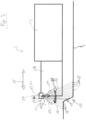
- Figure 1 1 shows a schematic side view of a road paver 1.
- the road paver 1 may include a tractor 2.
- the road paver may include a screed 3.
- the tractor 2 may be configured to tow the screed 3.
- the road paver 1 may include towing arms 4.
- the road paver 1 may be configured to apply a road surface 5 to a subsoil 6.
- the road paver 1 may move in a direction of travel 7.
- the screed 3 may comprise side shifters 8.
- the side shifters 8 may be configured to provide a paving width 9 (see Figure 2 ) of the paving screed 3.
- the side shifters 8 can be configured to limit the paving width 9 in a direction transverse to the direction of travel 7.
- the road paver 1 can further comprise an edge detection system 10.
- the edge detection system 10 can comprise a sensor unit 11.
- the sensor unit 11 can be arranged on one of the side shifters 8.
- the road paver 1 is shown in a schematic plan view from above.
- the paving screed 3 can comprise a base screed 12.
- the paving screed 3, as in the present embodiment, can comprise two extension parts 13.
- the extension parts 13 can be movable relative to the base screed 12, in particular in an extension direction 15.
- the extension direction 15 can be oriented transversely, in particular orthogonally, to the direction of travel 7.
- the edge detection system 10 can comprise a second sensor unit 14.
- the sensor unit 11 and the second sensor unit 14 can be arranged on opposite extension parts 13, in particular on opposite side shifters 8, of the paving screed 3.
- the sensor unit 11 can be configured to emit laser pulse sequences 16.
- the sensor unit 11 can be configured to emit laser pulse sequences in a plurality of directions 17.
- the sensor unit 11 can be configured to 16 such that they are reflected at a plurality of locations 18 of a surface 19 to be scanned.
- a section of the substrate 6 can be regarded as a surface 19 to be scanned.
- the reflections of the laser pulse sequences 16 can be detected by the sensor unit 11.
- reflections of the laser pulse sequences 16 can be detected by a photodiode (not shown) of the sensor unit 11.
- the sensor unit 11 and/or the edge detection system 10 can further be configured to determine a distance of the respective location 18 from the sensor unit 11 based on the propagation times of the laser pulse sequences 16 and their reflections. Based on this distance and the direction 17 of the respective laser pulse sequence, the sensor unit 11 and/or the edge detection system 10 can be configured to generate polar coordinate signals. Each polar coordinate signal can be representative of a position of the respective location 18 relative to a polar coordinate system, the origin of which can, for example, be in the sensor unit 11.
- the edge detection system 10 and/or the sensor unit 11 can further be configured to generate Cartesian coordinate signals based on the polar coordinate signals.
- the Cartesian coordinate signals can represent Cartesian coordinates of the respective locations relative to a Cartesian coordinate system 20.
- the origin of the Cartesian coordinate system 20 can be located in the sensor unit 11, in particular at a point at which the laser pulse sequences 16 are deflected in the respective direction 17.
- the edge detection system 10 and/or the sensor unit 11 can be configured to generate an interpolating function 21 (see Figure 4 ).
- a schematic diagram of such an interpolating function 21 is shown in Figure 4 shown by way of example.
- the edge detection system 10 and/or the sensor unit 11 may further be configured to determine a smoothed function 22 based on the interpolating function 21.
- a schematic diagram of such a smoothed function 22 is shown in Figure 5 shown by way of example.
- the edge detection system 10 and/or the sensor unit 11 can be configured to determine a derivative function 23 based on the smoothed function 22, in particular by differentiating the smoothed function 22.
- a schematic diagram of such a derivative function 23 is shown by way of example in Figure 6 shown.
- the edge detection system 10 and/or the sensor unit 11 can be configured to determine the smallest minimum 24 and/or the largest maximum 25 of the derivative function 23. Based on the smallest minimum 24 of the derivative function 23 and/or the largest maximum 25 of the derivative function 23, an edge distance value 26 can be determined.
- the edge detection system 10 and/or the sensor unit 11 can be configured to determine the smallest minimum 24 and/or the largest maximum 25 of the derivative function 23 and/or based on the largest maximum 25 of the derivative function 23, to determine an edge distance value 26.
- the smallest minimum 24 of the derivative function 23 is used as the basis for determining the edge distance value 26, as will be explained in more detail later.
- an argument of the derivative function 23 can be determined at the smallest minimum 24 of the derivative function 23 as an edge distance value 26.
- the edge distance value 26 can be considered representative of an edge distance 27 (see Figure 3 ) between an edge 28 (see also Figure 3 ) in the surface 19 to be scanned and the sensor unit 11.
- the edge detection system 10 can comprise a control unit 32.
- the sensor unit 11 can be connected to a first connection 33 of the control unit 32.
- the second sensor unit 14 can be connected to a second connection 34 of the control unit 32.
- the connection between the sensor units 11, 14 and the control unit 32 can be implemented, for example, as an Ethernet.
- the sensor unit 11 can have a fixed IP address, based on which the control unit 32 can recognize a paving side of the sensor unit 11.
- the sensor unit 14 can have a fixed IP address, which can be different from the IP address of the sensor unit 11 and based on which the control unit 32 can determine a paving side of the second sensor unit 14.
- the first connection 33 and the second connection 34 can each be assigned to a paving side.
- the control unit 32 can be configured to determine on which installation side the respective sensor unit 11, 14 is arranged based on the connection to which the respective sensor unit 11, 14 is connected.
- the sensor unit 11 can be arranged on the extension part 13, in particular on the side shift 8, of the screed 3. As in the present embodiment in Figure 1 As shown, the sensor can be mounted such that a plane 29, in which the plurality of directions 17 lie, is oriented at an angle 30 to the ground 6 and/or to the direction of travel 7. By varying the angle 30, it is possible to adjust how far the surface 19 of the ground 6 to be scanned should be from a rear edge of the screed 3. By adjusting a mounting height of the sensor unit 11, a width of the surface to be scanned can be adjusted.
- the x-coordinate of the Cartesian coordinate system 20, or the argument of the functions determined relative to this coordinate system 20, can be oriented parallel to the extension direction 15 of the extension part 13.
- the x-coordinate of the Cartesian coordinate system 20 can become more positive in the direction of a reduction of the installation width 9 (in Figure 3 to the left), the x-coordinate of the Cartesian coordinate system 20 can become more negative.
- the x-coordinate of a coordinate system (not shown) which has an origin in the second sensor unit 14 can be oriented such that the x-coordinate becomes more positive in the direction of a reduction in the installation width 9.
- the edge detection system 10 can be configured to automatically detect on which side of the screed the sensor unit 11 or the second sensor unit 14 is arranged.
- the operator can set which type of edge should be detected, e.g., whether an outwardly sloping or rising edge should be detected.
- the edge detection system 10 can provide the user with a suggestion based on the first measurement data. This suggestion can be accepted or changed by the operator.
- the edge distance value 26 the smallest minimum 24 of the derivative function 23 or the largest maximum 25 of the derivative function 23 can be searched for.
- the operator can save the edge distance value 26 determined in this situation as a target value.
- a deviation may occur, for example, a difference between the target value and the edge distance value 26.
- the corresponding extension part 13 can then be controlled such that the deviation is compensated.
- fluctuating edge distance values 26 may be determined using the method of determining the edge distance value 26 explained above. Undesirable effects of this effect can be reduced by the inertia of the adjustment behavior of the screed, particularly the extending parts 13. If the effects of the described effect are to be further reduced, the progression of the edge distance value 26 can be dampened and thus smoothed using a suitable filter, for example, a low-pass filter.
- the edge distance value can be subjected to a plausibility check before it is taken into account when adjusting the extension part 13.
- a plausibility window can be defined around the target value. If the edge distance value 26 lies within this plausibility window, the calculated difference between the target value and the edge distance value 26 can be taken into account when adjusting the extension part 13. If the edge distance value 26 lies outside the plausibility window, the difference between the target value and the edge distance value 26 can be assumed to be 0, so that the edge distance value 26 assessed as implausible can be disregarded when adjusting the extension part 13.
Landscapes
- Engineering & Computer Science (AREA)
- Physics & Mathematics (AREA)
- Electromagnetism (AREA)
- Remote Sensing (AREA)
- General Physics & Mathematics (AREA)
- Radar, Positioning & Navigation (AREA)
- Computer Networks & Wireless Communication (AREA)
- Architecture (AREA)
- Civil Engineering (AREA)
- Structural Engineering (AREA)
- Optics & Photonics (AREA)
- Road Paving Machines (AREA)
- Length Measuring Devices By Optical Means (AREA)
Priority Applications (5)
| Application Number | Priority Date | Filing Date | Title |
|---|---|---|---|
| EP23198331.3A EP4528331A1 (fr) | 2023-09-19 | 2023-09-19 | Système de détection de bord et procédé de détection d'un bord |
| JP2024157888A JP2025064969A (ja) | 2023-09-19 | 2024-09-12 | 縁部検出システム及び縁部の検出方法 |
| CN202411309891.9A CN119665807A (zh) | 2023-09-19 | 2024-09-19 | 边缘检测系统和检测边缘的方法 |
| CN202422289584.0U CN223512693U (zh) | 2023-09-19 | 2024-09-19 | 边缘检测系统、熨平板和道路摊铺机 |
| US18/889,639 US20250092618A1 (en) | 2023-09-19 | 2024-09-19 | Edge detection system and method of detecting an edge |
Applications Claiming Priority (1)
| Application Number | Priority Date | Filing Date | Title |
|---|---|---|---|
| EP23198331.3A EP4528331A1 (fr) | 2023-09-19 | 2023-09-19 | Système de détection de bord et procédé de détection d'un bord |
Publications (1)
| Publication Number | Publication Date |
|---|---|
| EP4528331A1 true EP4528331A1 (fr) | 2025-03-26 |
Family
ID=88097377
Family Applications (1)
| Application Number | Title | Priority Date | Filing Date |
|---|---|---|---|
| EP23198331.3A Pending EP4528331A1 (fr) | 2023-09-19 | 2023-09-19 | Système de détection de bord et procédé de détection d'un bord |
Country Status (4)
| Country | Link |
|---|---|
| US (1) | US20250092618A1 (fr) |
| EP (1) | EP4528331A1 (fr) |
| JP (1) | JP2025064969A (fr) |
| CN (2) | CN119665807A (fr) |
Citations (4)
| Publication number | Priority date | Publication date | Assignee | Title |
|---|---|---|---|---|
| US20080289558A1 (en) * | 2004-06-29 | 2008-11-27 | Peter James Montgomery | Lasar Scanning for Mooring Robot |
| WO2020088782A1 (fr) | 2018-11-02 | 2020-05-07 | Moba Mobile Automation Ag | Système de capteurs pour un finisseur de route |
| US20210337734A1 (en) * | 2018-10-08 | 2021-11-04 | Advanced Farm Technologies, Inc. | Autonomous crop harvester |
| DE202018006746U1 (de) * | 2018-11-02 | 2022-08-30 | Moba Mobile Automation Aktiengesellschaft | Sensorsystem für einen Straßenfertiger |
-
2023
- 2023-09-19 EP EP23198331.3A patent/EP4528331A1/fr active Pending
-
2024
- 2024-09-12 JP JP2024157888A patent/JP2025064969A/ja active Pending
- 2024-09-19 CN CN202411309891.9A patent/CN119665807A/zh active Pending
- 2024-09-19 US US18/889,639 patent/US20250092618A1/en active Pending
- 2024-09-19 CN CN202422289584.0U patent/CN223512693U/zh active Active
Patent Citations (4)
| Publication number | Priority date | Publication date | Assignee | Title |
|---|---|---|---|---|
| US20080289558A1 (en) * | 2004-06-29 | 2008-11-27 | Peter James Montgomery | Lasar Scanning for Mooring Robot |
| US20210337734A1 (en) * | 2018-10-08 | 2021-11-04 | Advanced Farm Technologies, Inc. | Autonomous crop harvester |
| WO2020088782A1 (fr) | 2018-11-02 | 2020-05-07 | Moba Mobile Automation Ag | Système de capteurs pour un finisseur de route |
| DE202018006746U1 (de) * | 2018-11-02 | 2022-08-30 | Moba Mobile Automation Aktiengesellschaft | Sensorsystem für einen Straßenfertiger |
Also Published As
| Publication number | Publication date |
|---|---|
| CN223512693U (zh) | 2025-11-04 |
| CN119665807A (zh) | 2025-03-21 |
| US20250092618A1 (en) | 2025-03-20 |
| JP2025064969A (ja) | 2025-04-17 |
Similar Documents
| Publication | Publication Date | Title |
|---|---|---|
| EP1339920B1 (fr) | Dispositif de reglage de hauteur au laser pour un engin de chantier | |
| DE602004003811T2 (de) | Objektdetektionssystem und verfahren zum erkennen eines objekts | |
| EP1664838B1 (fr) | Procede et programme informatique pour detecter le contour d'un obstacle dans l'environnement d'un vehicule | |
| EP2687631A1 (fr) | Finisseuse de route dotée d'un dispositif de mesure | |
| EP0547378B1 (fr) | Appareil de contrôle ultrasonore pour une fraiseuse mobile | |
| EP3550322B1 (fr) | Segment d'étalonnage destiné à l'étalonnage d'un système de mesure et procédé d'étalonnage d'un système de mesure | |
| EP1554606A1 (fr) | Procede pour identifier et suivre des objets | |
| EP0913707A1 (fr) | Procédé pour mesurer sans contact la distance d'un objet selon le principe de triangulation à laser | |
| DE9214769U1 (de) | Ultraschallsensor-Regeleinrichtung für einen Straßenfertiger | |
| EP3874296B1 (fr) | Système de capteurs pour un finisseur de route | |
| WO2019076812A1 (fr) | Procédé de classification radar de la surface routière | |
| WO2021001341A1 (fr) | Étalonnage d'un système de capteur optique actif à l'aide d'une cible d'étalonnage | |
| WO2005061985A2 (fr) | Procede et dispositif de determination de la position d'au moins un point de reflexion sur un obstacle | |
| DE102014115260B3 (de) | Sicherheitssystem zur Absicherung der Umgebung eines Objekts | |
| DE19754220B4 (de) | Verfahren und Vorrichtung zur Erkennung einer bevorstehenden oder möglichen Kollision | |
| WO2003050562A1 (fr) | Procede d'identification d'obstacles pour une automobile, avec au moins trois detecteurs de distance pour detecter l'extension laterale d'un objet | |
| EP3990944B1 (fr) | Détermination d'un angle de tangage d'un système de détection optique actif | |
| EP1433002B1 (fr) | Procede pour determiner la position d'un objet cible et systeme radar actionne selon ledit procede | |
| DE102021100695A1 (de) | Verfahren zum Betrieb eines Topologie-erfassenden Radarsystems innerhalb eines Behälters | |
| DE202018006746U1 (de) | Sensorsystem für einen Straßenfertiger | |
| EP4327121A1 (fr) | Dispositif de déviation de signal pour dévier des faisceaux de signaux électromagnétiques d'un appareil de détection, appareil de détection, véhicule comprenant au moins un appareil de détection et procédé pour faire fonctionner un dispositif de déviation de signal | |
| EP4040188B1 (fr) | Dispositif et procédé de mesure d'un objet | |
| DE102011001713B3 (de) | Einrichtung zur Ortsbestimmung eines Objektes in einem Raumwinkelbereich und Informationsübertragung | |
| EP2320248B1 (fr) | Procédé de détection d'un objet dans un angle mort d'un véhicule et système d'assistance au conducteur pour la détection d'un objet dans un angle mort d'un véhicule | |
| AT400908B (de) | Vorrichtung zur erfassung und messung unregelmässiger werkstücke, wie bohlen, mittels strahlen |
Legal Events
| Date | Code | Title | Description |
|---|---|---|---|
| PUAI | Public reference made under article 153(3) epc to a published international application that has entered the european phase |
Free format text: ORIGINAL CODE: 0009012 |
|
| STAA | Information on the status of an ep patent application or granted ep patent |
Free format text: STATUS: THE APPLICATION HAS BEEN PUBLISHED |
|
| AK | Designated contracting states |
Kind code of ref document: A1 Designated state(s): AL AT BE BG CH CY CZ DE DK EE ES FI FR GB GR HR HU IE IS IT LI LT LU LV MC ME MK MT NL NO PL PT RO RS SE SI SK SM TR |
|
| STAA | Information on the status of an ep patent application or granted ep patent |
Free format text: STATUS: REQUEST FOR EXAMINATION WAS MADE |
|
| 17P | Request for examination filed |
Effective date: 20250926 |
|
| P01 | Opt-out of the competence of the unified patent court (upc) registered |
Free format text: CASE NUMBER: UPC_APP_0005939_4528331/2026 Effective date: 20260218 |