EP4528355A1 - Système d'imagerie biologique et appareil de détection optique - Google Patents
Système d'imagerie biologique et appareil de détection optique Download PDFInfo
- Publication number
- EP4528355A1 EP4528355A1 EP23887178.4A EP23887178A EP4528355A1 EP 4528355 A1 EP4528355 A1 EP 4528355A1 EP 23887178 A EP23887178 A EP 23887178A EP 4528355 A1 EP4528355 A1 EP 4528355A1
- Authority
- EP
- European Patent Office
- Prior art keywords
- lens
- imaging system
- biological body
- lens set
- object side
- Prior art date
- Legal status (The legal status is an assumption and is not a legal conclusion. Google has not performed a legal analysis and makes no representation as to the accuracy of the status listed.)
- Granted
Links
Images


Classifications
-
- G—PHYSICS
- G02—OPTICS
- G02B—OPTICAL ELEMENTS, SYSTEMS OR APPARATUS
- G02B23/00—Telescopes, e.g. binoculars; Periscopes; Instruments for viewing the inside of hollow bodies; Viewfinders; Optical aiming or sighting devices
- G02B23/24—Instruments or systems for viewing the inside of hollow bodies, e.g. fibrescopes
- G02B23/2407—Optical details
- G02B23/2423—Optical details of the distal end
- G02B23/243—Objectives for endoscopes
-
- A—HUMAN NECESSITIES
- A61—MEDICAL OR VETERINARY SCIENCE; HYGIENE
- A61B—DIAGNOSIS; SURGERY; IDENTIFICATION
- A61B1/00—Instruments for performing medical examinations of the interior of cavities or tubes of the body by visual or photographical inspection, e.g. endoscopes; Illuminating arrangements therefor
- A61B1/00163—Optical arrangements
- A61B1/00188—Optical arrangements with focusing or zooming features
-
- G—PHYSICS
- G02—OPTICS
- G02B—OPTICAL ELEMENTS, SYSTEMS OR APPARATUS
- G02B13/00—Optical objectives specially designed for the purposes specified below
-
- G—PHYSICS
- G02—OPTICS
- G02B—OPTICAL ELEMENTS, SYSTEMS OR APPARATUS
- G02B13/00—Optical objectives specially designed for the purposes specified below
- G02B13/18—Optical objectives specially designed for the purposes specified below with lenses having one or more non-spherical faces, e.g. for reducing geometrical aberration
-
- G—PHYSICS
- G02—OPTICS
- G02B—OPTICAL ELEMENTS, SYSTEMS OR APPARATUS
- G02B13/00—Optical objectives specially designed for the purposes specified below
- G02B13/22—Telecentric objectives or lens systems
-
- G—PHYSICS
- G02—OPTICS
- G02B—OPTICAL ELEMENTS, SYSTEMS OR APPARATUS
- G02B23/00—Telescopes, e.g. binoculars; Periscopes; Instruments for viewing the inside of hollow bodies; Viewfinders; Optical aiming or sighting devices
- G02B23/24—Instruments or systems for viewing the inside of hollow bodies, e.g. fibrescopes
- G02B23/2407—Optical details
- G02B23/2415—Stereoscopic endoscopes
-
- G—PHYSICS
- G02—OPTICS
- G02B—OPTICAL ELEMENTS, SYSTEMS OR APPARATUS
- G02B9/00—Optical objectives characterised both by the number of the components and their arrangements according to their sign, i.e. + or -
- G02B9/64—Optical objectives characterised both by the number of the components and their arrangements according to their sign, i.e. + or - having more than six components
Definitions
- the present invention relates to the field of optical technologies, and in particular to, a biological body imaging system and an optical inspection device.
- An endoscope is a device that examines or treats tissues in the human body using a head probe and optical lenses based on the operation principles of optical imaging and probe technology. With a light source and lenses introduced into body cavities or tissues, microscopic structures or pathological tissues inside the body can be observed.
- the optical imaging principle of the endoscope means that light of a light source behind the human body enters into the body, and is reflected by an inner wall of an endoscope head and then guided by optical fibers to observation equipment. The optical lens of the endoscope focuses the light, thereby forming an enlarged image for the doctor's observation. Therefore, the quality of the optical imaging directly affects the use effect of the endoscope.
- the optical imaging of the endoscope mainly relies on the optical system arranged therein.
- the optical system is formed by an object lens, a lens set, and an eyepiece arranged sequentially from the front end at which a biological tissue is located to the rear end.
- the object lens is used to collect information of the biological tissue for imaging
- the lens set is used to transmit the image
- the eyepiece is used to enlarge the image for clinical observation by the doctor.
- the foundation of optical imaging is the biological tissue information collected by the object lens. Therefore, the collection of biological tissue information is an indispensable and crucial part.
- the quality of the object lens imaging effect depends on many factors, such as the basic imaging performance and imaging aberrations of the object lens. How to ensure the imaging effect of the object lens is a problem to be resolved urgently.
- the object lens produces a relatively clear image based on the collected biological tissue information, when the lens sets transmit the image, the optical loss due to long-distance transmission in the endoscope is likely to lower the image quality.
- An objective of the present invention is to resolve the problem of poor imaging effect of the object lens in the prior art and the problem of optical loss of the image during long-distance transmission.
- the present invention provides a biological body imaging system, including: a first lens set with a positive focal power, a second lens set with a positive focal power, a third lens set with a positive focal power, and a fourth lens set with a positive focal power that are sequentially arranged from an object side along a same optical axis.
- the first lens set includes a second lens with a plane facing the object side
- the second lens set includes a fourth lens with a convex surface facing the object side and a fifth lens with a convex surface facing an image side that fit with each other
- the third lens set includes a sixth lens with a convex surface facing the object side and a concave surface facing the image side
- the fourth lens set includes a seventh lens with a concave surface facing the object side and a convex surface facing the image side and an eighth lens with a convex surface facing the object side and a concave surface facing the image side.
- a combined focal length f 1 of the first lens set and a conjugate distance T satisfy 0.15 ⁇ f 1 T ⁇ 0.18
- a combined focal length f 4 of the fourth lens set and the combined focal length f 1 of the first lens set satisfy 1.8 ⁇ f 4 f 1 ⁇ 2.2
- a focal length f 41 of the seventh lens and a focal length f 42 of the eighth lens satisfy ⁇ 1 ⁇ f 42 f 41 ⁇ ⁇ 0.8 .
- the first lens set further includes a third lens disposed on an image side of the second lens along the same optical axis; and a surface of the third lens facing the image side forms a convex surface.
- a surface of the third lens facing the object side forms a convex surface or a plane.
- the first lens set further includes a first lens disposed on an object side of the second lens along the same optical axis and having a plane facing the object side.
- the first lens fits with the second lens, and surfaces of the first lens on the object side and the image side both form planes.
- a curvature radius r 4 corresponding to the surface of the third lens facing the object side, an operating distance H of the biological body imaging system, and an air gap H 1 between the second lens and the third lens satisfy 4.75 ⁇ r 4 H + H 1 ⁇ 15.9 .
- the operating distance H refers to a distance corresponding to a gap between a central position of the surface of the second lens facing the object side and a biological body
- the air gap H 1 refers to a distance corresponding to a gap between a central position of the second lens and a central position of the third lens.
- the combined focal length f 1 of the first lens set and a combined focal length f 2 of the second lens set satisfy 7 ⁇ f 2 f 1 ⁇ 11.5 .
- a combined focal length f 2 of the second lens set and a combined focal length f 3 of the third lens set satisfy 2.2 ⁇ f 2 f 3 ⁇ 4.5 .
- a curvature radius r 3 corresponding to the surface of the second lens facing the image side and a focal length f 12 of the second lens satisfy ⁇ 0.91 ⁇ r 3 f 12 ⁇ ⁇ 0.81 .
- a curvature radius r 9 corresponding to the surface of the sixth lens facing the object side and a combined focal length f 3 of the third lens set satisfy 0.15 ⁇ r 9 f 3 ⁇ 0.35 .
- a curvature radius r 12 corresponding to the surface of the seventh lens facing the image side and a curvature radius r 13 corresponding to the surface of the eighth lens facing the object side satisfy ⁇ 0.7 ⁇ r 12 r 13 ⁇ ⁇ 0.5 .
- a central thickness D 9 of the sixth lens and the conjugate distance T satisfy 0.13 ⁇ D 9 T .
- the present invention further provides an optical inspection device.
- the optical inspection device includes the biological body imaging system according to any one of descriptions in the first aspect.
- the parameter data (for example, numerical aperture, field of view) of the biological body imaging system is controlled using the first lens set, to determine the basic performance of the biological body imaging system.
- the second lens set is used to correct aberrations, which are mainly spherical aberration, comatic aberration, and chromatic aberration.
- the third lens set is used to achieve finite conjugate-distance imaging and correct field curvature.
- the fourth lens set is used to achieve telecentric imaging in the image space, thus ensuring the imaging effect of the biological body imaging system and further guaranteeing clarity of images during long-distance transmission through telecentric imaging in the image space, so as to reduce the optical loss during long-distance transmission.
- FIG. 1 is a structural cross-sectional view of a biological body imaging system 10 including an optical axis A in a first lens combination manner according to the present invention, where the first lens combination manner means that a first lens set 11, a second lens set 12, a third lens set 13, and a fourth lens set 14 form the biological body imaging system 10;
- FIG. 1 is a structural cross-sectional view of a biological body imaging system 10 including an optical axis A in a first lens combination manner according to the present invention, where the first lens combination manner means that a first lens set 11, a second lens set 12, a third lens set 13, and a fourth lens set 14 form the biological body imaging system 10;
- FIG. 1 is a structural cross-sectional view of a biological body imaging system 10 including an optical axis A in a first lens combination manner according to the present invention, where the first lens combination manner means that a first lens set 11, a second lens set 12, a third lens set 13, and a fourth lens set 14 form the biological body imaging system 10;
- FIG. 1 is
- FIG. 2 is a structural cross-sectional view of a biological body imaging system 10a including an optical axis A in a second lens combination manner according to the present invention, where the second lens combination manner means a first lens set 11, a third lens set 13, and a fourth lens set 14 form the biological body imaging system 10a; and
- FIG. 3 is a structural cross-sectional view of a biological body imaging system 10b including an optical axis A in a third lens combination manner according to the present invention, where the third lens combination manner means a first lens set 11, a second lens set 12, a third lens set 13 form the biological body imaging system 10b.
- the left side is the object side
- the right side is the image side.
- the lenses that is, the first lens 111 to the eighth lens 142 included by biological body imaging systems (that is, the biological body imaging system 10, the biological body imaging system 10a, and the biological body imaging system 10b) are defined as optical elements.
- biological body imaging systems that is, the biological body imaging system 10, the biological body imaging system 10a, and the biological body imaging system 10b
- an end of the biological body imaging system close to the object side is immersed in normal saline to form a layer of physiological saline at the end.
- the normal saline can be also defined as an optical element.
- “MTF" in the "MTF graph” of the present invention stands for modulation transfer function. In the transfer function, the abscissa represents spatial frequency in the unit of cycles per millimeter, and the ordinate represents the image contrast of the corresponding spatial frequency.
- the present invention shows specific implementations of a biological body imaging system.
- the biological body imaging system is mounted at an optical inspection device for observing a biological body (which includes a living creature or a detached biological tissue), and is specifically mounted at an end of the optical inspection device to optically image the biological body, so as to produce a biological body image for observation by the operator.
- the optical inspection device may be, for example, an endoscope, which is designed to enter the human body through a natural cavity or a small surgical incision in the body.
- the biological body imaging system is mounted in a hollow cavity formed at an end of the endoscope, and the endoscope is guided to an organ requiring examination, so as to obtain the corresponding images of the organ requiring examination for observation by the medical personnel.
- the optical inspection device may alternatively be a device used for crack detection in the industrial sector. This is not limited in this embodiment, but does not limit the protection scope of this application.
- the biological body imaging system 10 includes a first lens set 11 with a positive focal power, a second lens set 12 with a positive focal power, a third lens set 13 with a positive focal power, and a fourth lens set 14 with a positive focal power that are sequentially arranged from an object side along the same optical axis (that is, the optical axis A shown in FIG. 1 ).
- the first lens set 11 is used for setting parameter data (for example, numerical aperture, field of view) of the biological body imaging system 10, determining the basic performance of the biological body imaging system 10.
- the second lens set 12 is disposed between the first lens set 11 and the third lens set 13 along the same optical axis to correct aberrations, which are mainly spherical aberration, comatic aberration, and chromatic aberration.
- the third lens set 13 is configured to achieve finite conjugate-distance imaging and also to correct field curvature.
- the fourth lens set 14 is configured to achieve telecentric imaging in the image space, thus ensuring the imaging effect of the biological body imaging system 10. Additionally, it can further guarantee clarity of images during long-distance transmission through telecentric imaging in the image space, reducing the optical loss during long-distance transmission.
- the telecentric imaging in the image space is to enable a chief ray in each off-axis field of view in the image space to be parallel to the optical axis (or approximately parallel to the optical axis), and non-telecentric imaging in the image space is to enable the chief ray in each off-axis field of view not to be parallel to the optical axis.
- the chief rays are typically located at the center of the defocused spot corresponding to the field of view in the image space. When the chief ray is on the image plane, the defocused spot is minimized, and when the chief ray is behind the image plane, the defocused spot gradually becomes large.
- the chief ray is not changed in height and angle, and for a non-telecentric system, the chief ray increases in height and remains unchanged in angle.
- the telecentric system requires a smaller diameter and deflection angle of the receiving system than the non-telecentric system. It can be therefore seen that telecentric imaging in the image space can keep image clarity unchanged during long-distance transmission.
- the first lens set 11 includes a second lens 112 disposed along the optical axis A with a plane facing the object side.
- a surface of the second lens 112 facing the image side forms a convex surface.
- Light rays reflected by the surface of the biological body sequentially pass through the plane and the convex surface respectively formed on the object side and the image side of the second lens 112 to be gathered, effectively avoiding the problem that the reflected light rays cannot pass through the second lens set 12 due to the large reflection angle, thus reducing light loss.
- the surface of the second lens 112 facing the object side may be a convex surface or a plane, and is preferably a plane, so as to prevent or reduce the residual attachment such as liquid on the surface (that is, the surface of the second lens 112 facing the object side) when the biological body imaging system 10 is carried on the optical inspection device for use.
- the first lens set 11 further includes a third lens 113 disposed on the image side of the second lens 112 along the same optical axis A.
- the surface of the third lens 113 facing the image side forms a convex surface.
- the light rays reflected by the surface of the object are refracted by the second lens 112 to form refracted light rays.
- the third lens 113 is disposed on the image side of the second lens 112 to perform secondary gathering on the light rays refracted by the second lens 112, further avoiding the problem that the refracted light rays are unable to pass through the second lens set 12 due to a large refraction angle (which is equivalent to the refraction angle formed by the optical axis A), thus reducing the light loss.
- the surface of the third lens 113 facing the object side forms a convex surface or a plane.
- the plane that is, a plane of the third lens 113 facing the object side
- the plane does not gather the refracted light rays, which undergo second gathering only by the convex surface of the third lens 113 facing the image side. This avoids the problem that the refracted light rays are unable to pass through the second lens set 12 due to a large refraction angle, thus reducing light loss.
- the surface of the third lens 113 facing the object side may be a convex surface or a plane as long as the third lens 113 can gather the light rays refracted by the second lens 112.
- the first lens 111 is arranged as a flat lens, avoiding the change in optical path when the reflected light rays pass through the first lens 111, where due to such change, some or all of the refracted light rays cannot pass through the second lens 112, thus reducing light loss, that is, reducing the interference of the first lens 111 with the optical path of the reflected light rays.
- the first lens 111 may also be normal saline.
- the second lens 112 alone may form a first lens set 11, the second lens 112 and the third lens 113 are combined to form the first lens set 11, the first lens 111 and the second lens 112 are combined to form the first lens set 11, or the first lens 111, the second lens 112, and the third lens 113 are combined to form the first lens set 11.
- the combination manner of the first lens set 11 is not specifically limited in this embodiment. Any one of the foregoing cases stands as long as the first lens set 11 can gather the light rays reflected by the surface of the biological body surface, such that the parameter data of the biological body imaging system 10 is set, such as the numerical aperture, field of view.
- the first lens 111 is a flat lens
- the second lens 112 is a plano-convex lens
- the third lens 113 is a double-convex lens.
- the first lens 111 may fit with the second lens 112 and the surfaces of the first lens 111 on the object side and image side are both planes.
- the fitting arrangement means that the surface of the first lens 111 facing the image side and the surface of the second lens 112 facing the object side fit into one surface, so as to eliminate refraction losses by two surfaces (that is, the surface of the first lens 111 facing the image side and the surface of the second lens 112 facing the object side) and prevent total refraction in the gap.
- This further is conducive to mounting the first lens 111 and the second lens 112.
- the gap between the first lens 111 and the second lens 112 may be vacuumed, to reduce the interference of air with refracted light.
- the second lens set 12 includes a fourth lens 121 with a convex surface facing the object side and a fifth lens 122 with a convex surface facing the image side that fit with each other along the same optical axis A.
- the fourth lens 121 has a convex surface facing the object side and a concave surface facing the image side, and the surface of the fifth lens 122 facing the image side and the surface facing the object side are both convex surfaces.
- the refracted light rays passing through the first lens set 11 sequentially pass through the fourth lens 121 and the fifth lens 122.
- the fourth lens 121 diverges the refracted light rays passing through the first lens set 11, and the fifth lens 122 gathers the refracted light rays passing through the fourth lens 121, so as to correct spherical aberration, comatic aberration, and chromatic aberration.
- the arrangement manner of the fourth lens 121 and the fifth lens 122 may be fitting as described above. That is, the surface of the fourth lens 121 facing the image side fits with the surface of the fifth lens 122 facing the object side, to form the second lens set 12 which has a positive focal power, so as to eliminate refraction losses by two surfaces (that is, the surface of the fourth lens 121 facing the image side and the surface of the fifth lens 122 facing the object side) and prevent total refraction in the gap. This is also conducive to mounting the fourth lens 121 and the fifth lens 122. Certainly, as described above, the gap between the fourth lens 121 and the fifth lens 122 may also be vacuumed to reduce the interference of the gap with refracted light.
- the third lens set 13 includes a sixth lens 131 arranged along the same optical axis A.
- the surface of the sixth lens 131 facing the object side forms a convex surface
- the surface of the sixth lens 131 facing the image side forms a concave surface, such that the convex surface gathers the refracted light rays from the second lens set 12 (or the first lens set 11), and the concave surface diverges refracted light rays from the convex surface, thus achieving finite conjugate-distance imaging and correcting field curvature (that is, curvature of the image field).
- the fourth lens set 14 includes a seventh lens 141 and an eighth lens 142 sequentially arranged from the object side along the same optical axis A.
- the surface of the seventh lens 141 facing the object side forms a concave surface, and the surface facing the image side forms a convex surface.
- the surface of the eighth lens 142 facing the object side forms a convex surface and the surface facing the image side forms a concave surface.
- the concave surface of the seventh lens 141 diverges the refracted light rays passing through the third lens set 13, and the convex surface of the seventh lens 141 gathers the refracted light rays.
- the convex surface of the eighth lens 142 gathers the refracted light rays passing through the seventh lens 141, and the concave surface of the eighth lens 142 diverges the refracted light rays, so as to achieve telecentric imaging in the image space.
- the first lens set 11, the second lens set 12, the third lens set 13, and the fourth lens set 14 may form the biological body imaging system 10.
- the parameter data (for example, numerical aperture, field of view) of the biological body imaging system 10 is controlled using the first lens set 11, to determine the basic performance of the biological body imaging system 10.
- the second lens set 12 is used to correct aberrations, which are mainly spherical aberration, comatic aberration, and chromatic aberration.
- the third lens set 13 is used to achieve finite conjugate-distance imaging and correct field curvature.
- the fourth lens set 14 is used to achieve telecentric imaging in the image space, thus ensuring the imaging effect of the biological body imaging system 10 and further guaranteeing clarity of images during long-distance transmission through telecentric imaging in the image space, so as to reduce the optical loss during long-distance transmission.
- the first lens set 11, the third lens set 13, and the fourth lens set 14 may alternatively form the biological body imaging system 10a to optically image the biological body with the fourth lens set 14 achieving telecentric imaging in the image space, thus ensuring the imaging effect of the biological body imaging system 10 and further ensuring the image clarity during long-distance transmission through telecentric imaging in the image space, so as to reduce optical loss during long-distance transmission.
- the first lens set 11, the second lens set 12, and the third lens set 13 may alternatively form the biological body imaging system 10b to optically image the biological body, which is not specifically limited in this embodiment, and the structure shown by the biological body imaging system 10 is preferably used.
- the second lens set 12 is used to correct aberrations, ensuring clarity of the biological body image
- the fourth lens set 14 is used to achieve telecentric imaging in the image space, further ensuring the clarity of the biological body image during long-distance transmission.
- each optical element satisfies the following condition:
- a combined focal length f 1 of the first lens set 11 and the conjugate distance T (that is, the conjugate distance T of the biological body imaging system 10) satisfy 0.15 ⁇ f 1 T ⁇ 0.18 .
- the combined focal length f 1 of the first lens set 11 and the combined focal length f 2 of the second lens set 12 satisfy 7 ⁇ f 2 f 1 ⁇ 11.5 .
- the combined focal length f 2 of the second lens set 12 and the combined focal length f 3 of the third lens set 13 satisfy 2.2 ⁇ f 2 f 3 ⁇ 4.5 .
- the combined focal length f 4 of the fourth lens set 14 and the combined focal length f 1 of the first lens set 11 satisfy 1.8 ⁇ f 4 f 1 ⁇ 2.2 .
- the focal length f 41 of the seventh lens 141 and the focal length f 42 of the eighth lens 142 satisfy ⁇ 1 ⁇ f 42 f 41 ⁇ ⁇ 0.8 .
- the curvature radius r 3 corresponding to the surface of the second lens 112 facing the image side and the focal length f 12 of the second lens 112 satisfy ⁇ 0.91 ⁇ r 3 f 12 ⁇ ⁇ 0.81 .
- the curvature radius r 9 corresponding to the convex surface of the sixth lens 131 facing the object side and the combined focal length f 3 of the third lens set 13 satisfy 0.15 ⁇ r 9 f 3 ⁇ 0.35 .
- the curvature radius r 12 corresponding to the convex surface of the seventh lens 141 facing the image side and the curvature radius r 13 corresponding to the convex surface of the eighth lens 142 facing the object side satisfy ⁇ 0.7 ⁇ r 12 r 13 ⁇ ⁇ 0.5 .
- the central thickness D 9 of the sixth lens 131 and the conjugate distance T satisfy 0.13 ⁇ D 9 T .
- the curvature radius r 4 corresponding to the surface of the third lens 113 facing the object side, the operating distance H of the biological body imaging system 10, and an air gap H 1 between the second lens 112 and the third lens 113 satisfy 4.75 ⁇ r 4 H + H 1 ⁇ 15.9 .
- the air gap H 1 refers to a distance corresponding to a gap between a central position of the second lens 112 and the central position of the third lens 113
- the operating distance H refers to a distance corresponding to a gap between a central position of a surface of the second lens 112 facing the object side and the biological body.
- FIG. 1 The lens structure of a biological body imaging system 10 in Embodiment 1 is shown in FIG. 1 .
- the biological body imaging system 10 in Embodiment 1 is formed by sequentially arranging a first lens set 11 with a positive focal power, a second lens set 12 with a positive focal power, a third lens set 13 with a positive focal power, and a fourth lens set 14 with a positive focal power from the object side along the same optical axis (that is, the optical axis A).
- the first lens set 11 is sequentially formed from the object side by a second lens 112 with a plane facing the object side and the third lens 113 with a convex surface facing the image side without the first lens 111, and immersed in normal saline before specific imaging to form a layer of normal saline on the surface of the second lens 112 facing the object side.
- the second lens set 12 is sequentially formed along the object side through fitting between a fourth lens 121 with a convex surface facing the object side and a fifth lens 122 with a convex surface facing the image side.
- the third lens set 13 is formed by a sixth lens 131 with a convex surface facing the object side.
- the fourth lens set 14 is sequentially formed from the object side by a seventh lens 141 with a concave surface facing the object side and an eighth lens 142 with a convex surface facing the object side.
- the second lens 112 to the eighth lens 142 are all spherical lenses.
- the basic parameter table of the optical elements included by the biological body imaging system 10 in Embodiment 1 shown in Table 1 includes serial number (i), curvature radius (r i ), central thickness (D i ), refractive index (Nd i ), and Abbe number (vd j ).
- the optical elements refer to the normal saline and the second lens 112 to the eighth lens 142.
- the fitting surfaces of two optical elements are defined as one surface (for example, the fourth lens 121 fits with the fifth lens 122, and the surface of the fourth lens 121 facing the image side and the surface of the fifth lens 122 facing the object side are defined as one surface). Moreover, the surface of the normal saline facing the image side and the surface of the second lens 112 facing the object side are defined as one surface.
- the column labeled curvature radius (r i ) represents a curvature radius of an i-th surface, and the symbol of the curvature radius (r i ) is positive when the surface facing the object side protrudes and is negative when the surface facing the image side protrudes.
- D 1 represents a distance (that is, a central thickness of the normal saline) corresponding to a gap between the first surface center position and the second surface center position
- D 2 represents a distance (that is, a central thickness of the second lens 112) corresponding to a gap between the second surface center position and the third surface center position
- D 3 represents a distance (that is, an air gap between the second lens 112 and the third lens 113) corresponding to a gap between the third surface center position and the fourth surface center position.
- D 13 represents a distance corresponding to a gap between the 13th surface center position and the 14th surface center position
- D 14 represents a distance corresponding to a gap between the 14th surface center position and an image surface formed by the biological body.
- the column labeled refractive index (Nd i ) represents a refractive index between the i-th surface and the i+1-th surface.
- Nd 1 represents a refractive index (that is, the refractive index of the normal saline) between the first surface and the second surface.
- Nd 2 represents a refractive index (that is, the refractive index of the second lens 112) between the second surface and the third surface.
- Nd 3 represents a refractive index (that is, the refractive index of air between the second lens 112 and the third lens 113) between the third refractive index and the fourth refractive index, ..., by analog.
- i is specifically defined sequentially from the object side to the image side in the foregoing description.
- j is specifically defined sequentially from the object side to the image side.
- the biological body imaging system 10 in Embodiment 1 has a numerical aperture (NA) of 0.5, a field of view of 0.5 (in the unit of, millimeter, mm) in the object space, telecentricity smaller than 0.2 (in the unit of, degree, °) in the image space, and an operating distance of 0.5 (in the unit of, millimeter, mm).
- NA numerical aperture
- mm a field of view of 0.5
- telecentricity smaller than 0.2
- an operating distance of 0.5 in the unit of, millimeter, mm
- mm is used as the length unit for the numerical values in Table 1, but used once as an example.
- the unit may be proportionally enlarged or reduced, allowing for the use of other appropriate units as well.
- Table 1 shows the values rounded to numbers with specified decimal places.
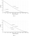
- FIG. 4 is an MTF graph of a biological body imaging system 10 (that is, which is formed by a first lens set 11, a second lens set 12, a third lens set 13, and a fourth lens set 14) at a field of view of 1.0 according to Embodiment 1;
- FIG. 5 is an MTF graph of a biological body imaging system 10a (that is, which is formed by a first lens set 11, a third lens set 13, and a fourth lens set 14) at a field of view of 1.0 according to Embodiment 1;
- FIG. 6 is an MTF graph of a biological body imaging system 10b (that is, which is formed by a first lens set 11, a second lens set 12, and a third lens set 13) at a field of view of 1.0 according to Embodiment 1.
- the abscissa in FIG. 4 represents spatial frequency in the unit of cycles per millimeter (cycles/mm).
- the spatial frequency ranges from 0 to 620, with intervals of 5 cycles per millimeter.
- Actual values (that is, ordinate values) on the Y-axis corresponding to line type 3 are respectively as follows: 1, 0.988823, 0.977607, 0.966306, 0.954857, 0.943218, 0.931446, 0.919606, 0.907723, 0.895815, 0.883894, 0.871974, 0.860067, 0.848184, 0.836321, 0.824479, 0.812669, 0.800896, 0.789156, 0.77745, 0.765788, 0.754175, 0.742606, 0.731084, 0.719625, 0.708231, 0.696881, 0.685578, 0.674352, 0.66327, 0.652425, 0.641792, 0.631215, 0.620642
- the abscissa in FIG. 5 represents spatial frequency in the unit of cycles per millimeter (cycles/mm).
- the spatial frequency ranges from 0 to 720, with intervals of 10 cycles per millimeter.
- Actual values (that is, ordinate values) on the Y-axis corresponding to line type 3 are respectively as follows: 1, 0.695346, 0.403169, 0.150239, 0.031339, 0.026561, 0.052371, 0.07776, 0.063535, 0.044861, 0.040827, 0.042849, 0.053615, 0.068224, 0.073411, 0.068164, 0.058676, 0.051014, 0.039108, 0.025228, 0.015465, 0.017495, 0.027212, 0.030791, 0.025944, 0.014651, 0.008479, 0.012901, 0.020772, 0.025449, 0.027474, 0.02882, 0.0286
- the abscissa in FIG. 6 represents spatial frequency in the unit of cycles per millimeter (cycles/mm).
- the spatial frequency ranges from 0 to 620, with intervals of 5 cycles per millimeter.
- Actual values (that is, ordinate values) on the Y-axis corresponding to line type 3 are respectively as follows: 1, 0.98621, 0.971682, 0.955875, 0.93896, 0.92124, 0.902913, 0.88416, 0.865186, 0.84618, 0.827276, 0.808594, 0.790239, 0.772293, 0.7548, 0.737794, 0.721296, 0.705319, 0.689857, 0.6749, 0.660429, 0.646424, 0.632859, 0.619711, 0.606955, 0.594625, 0.582828, 0.571532, 0.560531, 0.549732, 0.539181, 0.528893, 0.518838, 0.5089
- FIG. 7 is an MTF graph of a biological body imaging system 10 at a field of view of 0.707 according to Embodiment 1
- FIG. 8 is an MTF graph of a biological body imaging system 10a at a field of view of 0.707 according to Embodiment 1
- FIG. 9 is an MTF graph of a biological body imaging system 10b at a field of view of 0.707 according to Embodiment 1.
- the abscissa in FIG. 7 represents spatial frequency in the unit of cycles per millimeter (cycles/mm).
- the spatial frequency ranges from 0 to 620, with intervals of 5 cycles per millimeter.
- Actual values (that is, ordinate values) on the Y-axis corresponding to line type 3 are respectively as follows: 1, 0.989015, 0.978098, 0.967277, 0.956424, 0.945424, 0.934297, 0.923081, 0.911776, 0.900377, 0.888896, 0.877344, 0.865731, 0.854066, 0.842361, 0.830629, 0.818881, 0.80713, 0.795387, 0.783664, 0.771972, 0.760321, 0.748716, 0.737167, 0.725687, 0.714278, 0.702931, 0.691646, 0.680437, 0.669372, 0.658568, 0.648003, 0.637504, 0.6270
- the abscissa in FIG. 8 represents spatial frequency in the unit of cycles per millimeter (cycles/mm).
- the spatial frequency ranges from 0 to 720, with intervals of 10 cycles per millimeter.
- Actual values (that is, ordinate values) on the Y-axis corresponding to line type 3 are respectively as follows: 1, 0.700743, 0.329649, 0.167578, 0.204311, 228271, 0.173682, 0.116644, 0.118336, 0.136436, 0.119212, 0.082198, 0.050298, 0.040437, 0.057033, 0.07589, 0.068379, 0.04777, 0.030888, 0.028779, 0.033711, 0.032481, 0.027403, 0.030176, 0.038317, 0.038073, 0.031132, 0.023261, 0.02077, 0.023986, 0.028269, 0.031041, 0.032293, 0.03
- the abscissa in FIG. 9 represents spatial frequency in the unit of cycles per millimeter (cycles/mm).
- the spatial frequency ranges from 0 to 620, with intervals of 5 cycles per millimeter.
- Actual values (that is, ordinate values) on the Y-axis corresponding to line type 3 are respectively as follows: 1, 0.985227, 0.967729, 0.94554, 0.919441, 0.890654, 0.859789, 0.827384, 0.794145, 0.760753, 0.727736, 0.695549, 0.664533, 0.634964, 0.607008, 0.580772, 0.556269, 0.533478, 0.512335, 0.492752, 0.474605, 0.45777, 0.442126, 0.427553, 0.413937, 0.40115, 0.389055, 0.377609, 0.366892, 0.356837, 0.347206, 0.33786, 0.328781, 0.319942
- FIG. 10 is an MTF graph of a biological body imaging system 10 at a central field according to Embodiment 1
- FIG. 11 is an MTF graph of a biological body imaging system 10a at a central field of view according to Embodiment 1
- FIG. 12 is an MTF graph of a biological body imaging system 10b at a central field of view according to Embodiment 1.
- the abscissa in FIG. 10 represents spatial frequency in the unit of cycles per millimeter (cycles/mm).
- the spatial frequency ranges from 0 to 620, with intervals of 5 cycles per millimeter.
- Actual values (that is, ordinate values) on the Y-axis corresponding to line type 3 are respectively as follows: 1, 0.989061, 0.978207, 0.967478, 0.956748, 0.945899, 0.934956, 0.923957, 0.912905, 0.901796, 0.890642, 0.879456, 0.868245, 0.857018, 0.845786, 0.834559, 0.823345, 0.812153, 0.800991, 0.789866, 0.778784, 0.767751, 0.756767, 0.745838, 0.734969, 0.72416, 0.713403, 0.70269, 0.692023, 0.681463, 0.671142, 0.661037, 0.650971, 0.64
- the abscissa in FIG. 11 represents spatial frequency in the unit of cycles per millimeter (cycles/mm).
- the spatial frequency ranges from 0 to 720, with intervals of 10 cycles per millimeter.
- Actual values (that is, ordinate values) on the Y-axis corresponding to line type 3 are respectively as follows: 1, 0.629617, 0.230011, 0.212727, 0.256609, 0.15012, 0.121598, 0.149845, 0.08507, 0.048481, 0.083587, 0.087351, 0.047938, 0.037427, 0.063163, 0.067968, 0.044437, 0.029514, 0.030591, 0.041118, 0.051982, 0.053531, 0.046085, 0.039347, 0.035719, 0.031317, 0.025919, 0.021683, 0.020239, 0.021447, 0.024112, 0.027535, 0.031032,
- the abscissa in FIG. 12 represents spatial frequency in the unit of cycles per millimeter (cycles/mm).
- the spatial frequency ranges from 0 to 620, with intervals of 5 cycles per millimeter.
- Actual values (that is, ordinate values) on the Y-axis corresponding to line type 3 are respectively as follows: 1, 0.988792, 0.977352, 0.965478, 0.953084, 0.940138, 0.9267, 0.912844, 0.898628, 0.884114, 0.869389, 0.854542, 0.839647, 0.824779, 0.810012, 0.795415, 0.781047, 0.766955, 0.753174, 0.739735, 0.726666, 0.713983, 0.70168, 0.689753, 0.678211, 0.667044, 0.656226, 0.645724, 0.635504, 0.625607, 0.616155, 0.607118, 0.598307,
- line type 1 represents a diffraction-limited transfer function in the tangential direction
- line type 2 represents the diffraction-limited transfer function in the sagittal direction
- line type 3 represents the actual transfer function in the tangential direction
- line type 4 represents actual transfer function in the sagittal direction. It can be known from FIGs. 4 to 12 that in the ideal state, optimal imaging effect with low distortion can be achieved when the transfer function in the tangential direction (that is, line type 1) coincides with the transfer function in the sagittal direction (that is, line type 2).
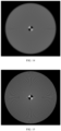
- FIG. 13 is a Siemens star chart of a biological body imaging system 10 according to Embodiment 1;
- FIG. 14 is a Siemens star chart of a biological body imaging system 10a according to Embodiment 1;
- FIG. 15 is a Siemens star chart of a biological body imaging system 10b according to Embodiment 1. It can be known from FIGs. 13 to 15 , compared with the Siemens star chart corresponding to the biological body imaging system 10a and the Siemens star chart corresponding to the biological body imaging system 10b, the Siemens star chart corresponding to the biological body imaging system 10 is clearest. Better resolution and higher contrast indicate clearer imaging.
- the structure of the optical element of a biological body imaging system 10 in Embodiment 2 is shown in FIG. 1 , and this structure is the same as that of the biological body imaging system 10 in Embodiment 1.
- the basic parameter table of the optical elements included by the biological body imaging system 10 in Embodiment 2 shown in Table 3 includes serial number (i), curvature radius (r i ), central thickness (D i ), refractive index (Nd i ), and Abbe number (vd j ).
- the biological body imaging system 10 in Embodiment 2 has a numerical aperture (NA) of 0.5, a field of view of 0.5 mm in the object space, telecentricity smaller than 0.2° in the image space, and an operating distance of 1.989.
- NA numerical aperture
- Table 3 Serial number (i) Curvature radius (r i ) Central thickness (D i ) Refractive index (Nd i ) Abbe number (vd j ) 1 ⁇ 1.994 1.333044 55.794 2 ⁇ 2.5 1.816000 46.621 3 -3.774 0.12 1.0 4 12.587 1.581 1.595220 67.736 5 -7.354 0.118 1.0 6 5.98 0.946 1.854779 24.799 7 2.31 1.619 1.497003 81.138 8 -14.931 0.139 1.0 9 2.042 2.509 1.618000 63.334 10 1.796 1.111 1.0 11 -0.919 1.161 1.89286 20.362 12 -1.933 1.61 1.0 13 3.397
- Table 4 shows calculated values of each optical element in Embodiment 2.
- Table 4 f 1 T f 2 f 1 f 2 f 3 f 4 f 1 f 42 f 41 r 3 f 12 r 9 f 3 r 12 r 13 D 9 T r 4 H + H 1 0.173 11.03 4.1 5 2.14 -0.88 -0.82 0.25 -0.57 0.14 5.95
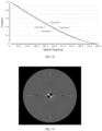
- FIGs. 16 to 18 are respective MTF graphs of a biological body imaging system 10 (that is, which is formed by a first lens set 11, a second lens set 12, a third lens set 13, and a fourth lens set 14) in a first lens combination manner at a field of view of 0.707, a field of view of 1.0, and a central field of view.
- FIG. 19 is a Siemens star chart of a biological body imaging system 10 (that is, which is formed by a first lens set 11, a second lens set 12, a third lens set 13, and a fourth lens set 14) in a first lens combination manner according to Embodiment 2.
- the abscissa in FIG. 16 represents spatial frequency in the unit of cycles per millimeter (cycles/mm).
- the spatial frequency ranges from 0 to 620, with intervals of 5 cycles per millimeter.
- Actual values (that is, ordinate values) on the Y-axis corresponding to line type 3 are respectively as follows: 1, 0.988939, 0.977875, 0.966782, 0.955542, 0.944059, 0.932363, 0.920499, 0.908478, 0.896309, 0.884016, 0.871623, 0.859148, 0.846613, 0.834041, 0.821455, 0.808877, 0.796328, 0.78383, 0.771402, 0.759065, 0.746835, 0.734722, 0.722741, 0.710908, 0.699228, 0.687692, 0.676296, 0.665056, 0.654033, 0.643341, 0.632952, 0.6226
- the abscissa in FIG. 17 represents spatial frequency in the unit of cycles per millimeter (cycles/mm).
- the spatial frequency ranges from 0 to 620, with intervals of 5 cycles per millimeter.
- Actual values (that is, ordinate values) on the Y-axis corresponding to line type 3 are respectively as follows: 1, 0.988603, 0.976989, 0.964987, 0.952579, 0.939807, 0.92678, 0.91361, 0.900372, 0.887122, 0.873901, 0.860743, 0.847683, 0.834742, 0.821919, 0.809214, 0.796645, 0.784221, 0.77193, 0.759768, 0.747748, 0.735874, 0.724134, 0.712526, 0.701067, 0.689756, 0.678561, 0.667482, 0.656555, 0.645841, 0.635412, 0.62523, 0.615143
- the abscissa in FIG. 18 represents spatial frequency in the unit of cycles per millimeter (cycles/mm).
- the spatial frequency ranges from 0 to 620, with intervals of 5 cycles per millimeter.
- Actual values (that is, ordinate values) on the Y-axis corresponding to line type 3 are respectively as follows: 1, 0.989048, 0.978154, 0.967336, 0.95647, 0.945441, 0.934274, 0.923009, 0.911646, 0.900187, 0.888646, 0.877041, 0.865384, 0.853691, 0.84198, 0.83027, 0.818577, 0.806917, 0.795307, 0.783762, 0.772296, 0.760919, 0.749638, 0.73846, 0.727395, 0.716444, 0.705601, 0.694856, 0.684203, 0.673702, 0.663485, 0.65353, 0.643652, 0.6
- line type 1 represents a diffraction-limited transfer function in the tangential direction
- line type 2 represents the diffraction-limited transfer function in the sagittal direction
- line type 3 represents the actual transfer function in the tangential direction
- line type 4 represents actual transfer function in the sagittal direction. It can be known from FIGs. 16 to 18 that in the ideal state, optimal imaging effect with low distortion can be achieved when the transfer function in the tangential direction (that is, line type 1) coincides with the transfer function in the sagittal direction (that is, line type 2).
- the structure of the optical element of a biological body imaging system 10 in Embodiment 2 is shown in FIG. 1 , and this structure is the same as that of the biological body imaging system 10 in Embodiment 1.
- the basic parameter table of the optical elements included by the biological body imaging system 10 in Embodiment 3 shown in Table 5 includes serial number (i), curvature radius (r i ), central thickness (D i ), refractive index (Nd i ), and Abbe number (vd j ).
- the biological body imaging system 10 in Embodiment 3 has a numerical aperture (NA) of 0.5, a field of view of 0.5 mm in the object space, telecentricity smaller than 0.2° in the image space, and an operating distance of 2.15 mm.
- NA numerical aperture
- Table 5 Serial number (i) Curvature radius (r i ) Central thickness (D i ) Refractive index (Nd i ) Abbe number (vd j ) 1 ⁇ 2.15 1.333044 55.794 2 ⁇ 1.96 1.816000 46.621 3 -3.546 0.141 1.0 4 36.342 1.318 1.595220 67.736 5 -5.794 0.115 1.0 6 7.487 0.943 1.854779 24.799 7 2.26 2.308 1.595220 67.736 8 -13.725 0.12 1.0 9 2.013 2.494 1.622800 56.913 10 1.565 1.087 1.0 11 -0.855 1.031 1.854779 24.799 12 -1.706
- Table 6 shows calculated values of each optical element in Embodiment 3.
- Table 6 f 1 T f 2 f 1 f 2 f 3 f 4 f 1 f 42 f 41 r 3 f 12 r 9 f 3 r 12 r 13 D 9 T r 4 H + H 1 0.170 7.2 2.24 1.99 -0.96 -0.82 0.20 -0.54 0.14 15.86
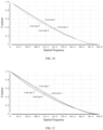
- FIG. 20 is an MTF graph of a biological body imaging system 10 (that is, which is formed by a first lens set 11, a second lens set 12, a third lens set 13, and a fourth lens set 14) at a field of view of 0.707 according to Embodiment 3;
- FIG. 21 is an MTF graph of a biological body imaging system 10 at a field of view of 1.0 according to Embodiment 3;
- FIG. 22 is an MTF graph of a biological body imaging system 10 at a central field of view according to Embodiment 1.
- FIG. 23 is a Siemens star chart of a biological body imaging system 10 (that is, which is formed by a first lens set 11, a second lens set 12, a third lens set 13, and a fourth lens set 14) in a first lens combination manner according to Embodiment 3.
- the abscissa in FIG. 20 represents spatial frequency in the unit of cycles per millimeter (cycles/mm).
- the spatial frequency ranges from 0 to 630, with intervals of 5 cycles per millimeter.
- Actual values (that is, ordinate values) on the Y-axis corresponding to line type 3 are respectively as follows: 1, 0.988963, 0.977883, 0.966706, 0.955349, 0.943742, 0.931908, 0.919885, 0.907686, 0.895322, 0.882814, 0.870187, 0.857467, 0.84468, 0.831857, 0.81903, 0.806228, 0.79348, 0.780815, 0.768257, 0.755832, 0.743558, 0.731448, 0.719512, 0.707768, 0.696227, 0.684867, 0.67367, 0.662667, 0.651902, 0.641439, 0.631304, 0.621373, 0.6
- the abscissa in FIG. 21 represents spatial frequency in the unit of cycles per millimeter (cycles/mm).
- the spatial frequency ranges from 0 to 630, with intervals of 5 cycles per millimeter.
- Actual values (that is, ordinate values) on the Y-axis corresponding to line type 3 are respectively as follows: 1, 0.988465, 0.976517, 0.963856, 0.950633, 0.937084, 0.923348, 0.909535, 0.895737, 0.882026, 0.868414, 0.854905, 0.841532, 0.828323, 0.81526, 0.802326, 0.789544, 0.776935, 0.764486, 0.752181, 0.740037, 0.728071, 0.716272, 0.704626, 0.693147, 0.681845, 0.670704, 0.659704, 0.648844, 0.638148, 0.627713, 0.617606, 0.607693
- the abscissa in FIG. 22 represents spatial frequency in the unit of cycles per millimeter (cycles/mm).
- the spatial frequency ranges from 0 to 630, with intervals of 5 cycles per millimeter.
- Actual values (that is, ordinate values) on the Y-axis corresponding to line type 3 are respectively as follows: 1, 0.989005, 0.977998, 0.966945, 0.95574, 0.944284, 0.932604, 0.920747, 0.908728, 0.896555, 0.884257, 0.871864, 0.859404, 0.846903, 0.834392, 0.821903, 0.809462, 0.797097, 0.78483, 0.772684, 0.760678, 0.748828, 0.73714, 0.72562, 0.714283, 0.703137, 0.692154, 0.68131, 0.670642, 0.6602, 0.650036, 0.640168, 0.630473, 0.620829, 0.611
- line type 1 represents a diffraction-limited transfer function in the tangential direction
- line type 2 represents the diffraction-limited transfer function in the sagittal direction
- line type 3 represents the actual transfer function in the tangential direction
- line type 4 represents actual transfer function in the sagittal direction. It can be known from FIGs. 20 to 22 that in the ideal state, optimal imaging effect with low distortion can be achieved when the transfer function in the tangential direction (that is, line type 1) coincides with the transfer function in the sagittal direction (that is, line type 2).
- the present invention further discloses an optical inspection device.
- the optical inspection device includes the biological body imaging system 10 as described above.
- the biological body imaging system 10 may be mounted on an inner side of the optical inspection device, to optically image tissue of the biological body (which includes a living creature or a detached biological tissue), thus allowing the operator (for example, medical personnel or scientific researcher) to observe the image of the biological body.
- tissue of the biological body which includes a living creature or a detached biological tissue
Landscapes
- Physics & Mathematics (AREA)
- Optics & Photonics (AREA)
- Health & Medical Sciences (AREA)
- General Physics & Mathematics (AREA)
- Life Sciences & Earth Sciences (AREA)
- Surgery (AREA)
- General Health & Medical Sciences (AREA)
- Radiology & Medical Imaging (AREA)
- Molecular Biology (AREA)
- Engineering & Computer Science (AREA)
- Biomedical Technology (AREA)
- Heart & Thoracic Surgery (AREA)
- Medical Informatics (AREA)
- Pathology (AREA)
- Animal Behavior & Ethology (AREA)
- Nuclear Medicine, Radiotherapy & Molecular Imaging (AREA)
- Public Health (AREA)
- Veterinary Medicine (AREA)
- Biophysics (AREA)
- Astronomy & Astrophysics (AREA)
- Lenses (AREA)
Applications Claiming Priority (2)
| Application Number | Priority Date | Filing Date | Title |
|---|---|---|---|
| CN202311227358.3A CN116974057B (zh) | 2023-09-22 | 2023-09-22 | 一种生物体成像系统与光学检测设备 |
| PCT/CN2023/134948 WO2024125298A1 (fr) | 2023-09-22 | 2023-11-29 | Système d'imagerie biologique et appareil de détection optique |
Publications (3)
| Publication Number | Publication Date |
|---|---|
| EP4528355A1 true EP4528355A1 (fr) | 2025-03-26 |
| EP4528355A4 EP4528355A4 (fr) | 2025-09-10 |
| EP4528355B1 EP4528355B1 (fr) | 2026-05-06 |
Family
ID=88477004
Family Applications (1)
| Application Number | Title | Priority Date | Filing Date |
|---|---|---|---|
| EP23887178.4A Active EP4528355B1 (fr) | 2023-09-22 | 2023-11-29 | Système d'imagerie biologique et appareil de détection optique |
Country Status (4)
| Country | Link |
|---|---|
| US (1) | US20250064304A1 (fr) |
| EP (1) | EP4528355B1 (fr) |
| CN (1) | CN116974057B (fr) |
| WO (1) | WO2024125298A1 (fr) |
Families Citing this family (3)
| Publication number | Priority date | Publication date | Assignee | Title |
|---|---|---|---|---|
| CN116974057B (zh) * | 2023-09-22 | 2023-12-08 | 上海树突精密仪器有限公司 | 一种生物体成像系统与光学检测设备 |
| CN120928543B (zh) * | 2025-10-10 | 2025-12-23 | 安徽树突光学科技有限公司 | 一种光学观测设备 |
| CN120928544B (zh) * | 2025-10-11 | 2025-12-26 | 清软微视(杭州)科技有限公司 | 一种用于晶圆表面缺陷检测的物镜镜头 |
Family Cites Families (15)
| Publication number | Priority date | Publication date | Assignee | Title |
|---|---|---|---|---|
| JPH05307139A (ja) * | 1992-04-28 | 1993-11-19 | Olympus Optical Co Ltd | 内視鏡対物レンズ |
| JP3426378B2 (ja) * | 1994-01-27 | 2003-07-14 | ペンタックス株式会社 | 内視鏡対物レンズ |
| JP4675348B2 (ja) * | 2007-03-09 | 2011-04-20 | オリンパスメディカルシステムズ株式会社 | 対物光学系 |
| WO2011070897A1 (fr) * | 2009-12-07 | 2011-06-16 | オリンパスメディカルシステムズ株式会社 | Objectif et dispositif endoscopique |
| JP6289132B2 (ja) * | 2014-01-31 | 2018-03-07 | キヤノン株式会社 | ズームレンズ及びそれを有する撮像装置 |
| JP6300558B2 (ja) * | 2014-02-14 | 2018-03-28 | キヤノン株式会社 | ズームレンズ及びそれを有する撮像装置 |
| CN105899993B (zh) * | 2014-08-28 | 2018-09-25 | 奥林巴斯株式会社 | 内窥镜物镜光学系统 |
| CN106324811B (zh) * | 2015-07-01 | 2018-11-02 | 大立光电股份有限公司 | 光学摄像镜头组、取像装置及电子装置 |
| WO2017043351A1 (fr) * | 2015-09-07 | 2017-03-16 | Hoya株式会社 | Système optique à puissance variable destiné à un endoscope, et endoscope |
| CN108279484B (zh) * | 2018-03-13 | 2024-01-26 | 浙江舜宇光学有限公司 | 光学成像系统 |
| CN108227151B (zh) * | 2018-03-16 | 2019-11-26 | 浙江舜宇光学有限公司 | 光学成像镜片组 |
| CN113589519B (zh) * | 2021-07-30 | 2024-08-27 | 舜宇光学(中山)有限公司 | 细管径高清内窥镜光学系统 |
| CN113633245B (zh) * | 2021-08-23 | 2023-10-13 | 华中科技大学鄂州工业技术研究院 | 一种探头式荧光共聚焦内窥镜耦合物镜光学系统 |
| CN113721361B (zh) * | 2021-11-02 | 2022-02-18 | 深圳康诺思腾科技有限公司 | 一种用于立体内窥镜的光学成像系统及立体内窥镜 |
| CN116974057B (zh) * | 2023-09-22 | 2023-12-08 | 上海树突精密仪器有限公司 | 一种生物体成像系统与光学检测设备 |
-
2023
- 2023-09-22 CN CN202311227358.3A patent/CN116974057B/zh active Active
- 2023-11-29 US US18/711,185 patent/US20250064304A1/en active Pending
- 2023-11-29 EP EP23887178.4A patent/EP4528355B1/fr active Active
- 2023-11-29 WO PCT/CN2023/134948 patent/WO2024125298A1/fr active Pending
Also Published As
| Publication number | Publication date |
|---|---|
| CN116974057A (zh) | 2023-10-31 |
| EP4528355A4 (fr) | 2025-09-10 |
| WO2024125298A1 (fr) | 2024-06-20 |
| EP4528355B1 (fr) | 2026-05-06 |
| CN116974057B (zh) | 2023-12-08 |
| US20250064304A1 (en) | 2025-02-27 |
Similar Documents
| Publication | Publication Date | Title |
|---|---|---|
| EP4528355A1 (fr) | Système d'imagerie biologique et appareil de détection optique | |
| US8139296B2 (en) | Reimaging optical system and endoscope using the same | |
| EP1980889B1 (fr) | Lentille d'objectif d'endoscope et endoscope | |
| EP2596740B1 (fr) | Lentille d'objectif pour actionneur de dispositif endoscopique pour système de focalisation et endoscopique | |
| JP4999078B2 (ja) | 内視鏡用対物レンズおよび内視鏡 | |
| JP4248771B2 (ja) | 内視鏡装置 | |
| US20250311916A1 (en) | Endoscopic same axis-maintaining system, coaxial optical system, and endoscopic imaging system and application thereof | |
| WO1988008271A1 (fr) | Dispositif optique de visionnement | |
| US8715170B2 (en) | Objective optical system for endoscope | |
| CN110873950A (zh) | 内窥镜物镜变焦光学系统 | |
| JP2008257109A (ja) | 内視鏡用対物レンズおよび内視鏡 | |
| US5980453A (en) | Endoscope with low distortion | |
| US5888193A (en) | Endoscope with curved optical axis | |
| CN119200207B (zh) | 一种消色差荧光腹腔镜光学系统 | |
| JP2017142295A (ja) | 内視鏡用対物レンズおよび内視鏡 | |
| RU2762784C2 (ru) | Релейная оптика для жесткого эндоскопа и эндоскоп | |
| CN208026985U (zh) | 微型高清医疗镜头 | |
| WO2018211595A1 (fr) | Système optique destiné à une visualisation stéréoscopique et dispositif d'imagerie équipé d'un tel système | |
| JPH07294807A (ja) | 観察部分と、結像光学系を内蔵する内視鏡鏡胴とを有する内視鏡 | |
| CN107874733B (zh) | 一种小口径内窥镜光学系统 | |
| CN112790721B (zh) | 一种高分辨率侧向成像的微型内窥显微物镜组及探头 | |
| CN214511102U (zh) | 一种广角内窥镜光学系统 | |
| CN206321859U (zh) | 内窥用摄像物镜光学系统 | |
| JP3530571B2 (ja) | 硬性内視鏡 | |
| JPH0968647A (ja) | 内視鏡対物レンズ |
Legal Events
| Date | Code | Title | Description |
|---|---|---|---|
| STAA | Information on the status of an ep patent application or granted ep patent |
Free format text: STATUS: UNKNOWN |
|
| STAA | Information on the status of an ep patent application or granted ep patent |
Free format text: STATUS: THE INTERNATIONAL PUBLICATION HAS BEEN MADE |
|
| PUAI | Public reference made under article 153(3) epc to a published international application that has entered the european phase |
Free format text: ORIGINAL CODE: 0009012 |
|
| STAA | Information on the status of an ep patent application or granted ep patent |
Free format text: STATUS: REQUEST FOR EXAMINATION WAS MADE |
|
| 17P | Request for examination filed |
Effective date: 20240516 |
|
| AK | Designated contracting states |
Kind code of ref document: A1 Designated state(s): AL AT BE BG CH CY CZ DE DK EE ES FI FR GB GR HR HU IE IS IT LI LT LU LV MC ME MK MT NL NO PL PT RO RS SE SI SK SM TR |
|
| A4 | Supplementary search report drawn up and despatched |
Effective date: 20250811 |
|
| RIC1 | Information provided on ipc code assigned before grant |
Ipc: G02B 23/24 20060101AFI20250805BHEP Ipc: G02B 13/22 20060101ALI20250805BHEP Ipc: A61B 1/00 20060101ALI20250805BHEP Ipc: G02B 9/64 20060101ALI20250805BHEP Ipc: G02B 13/00 20060101ALI20250805BHEP Ipc: G02B 13/18 20060101ALI20250805BHEP |
|
| GRAP | Despatch of communication of intention to grant a patent |
Free format text: ORIGINAL CODE: EPIDOSNIGR1 |
|
| STAA | Information on the status of an ep patent application or granted ep patent |
Free format text: STATUS: GRANT OF PATENT IS INTENDED |
|
| DAV | Request for validation of the european patent (deleted) | ||
| DAX | Request for extension of the european patent (deleted) | ||
| INTG | Intention to grant announced |
Effective date: 20260112 |
|
| GRAS | Grant fee paid |
Free format text: ORIGINAL CODE: EPIDOSNIGR3 |
|
| GRAA | (expected) grant |
Free format text: ORIGINAL CODE: 0009210 |
|
| STAA | Information on the status of an ep patent application or granted ep patent |
Free format text: STATUS: THE PATENT HAS BEEN GRANTED |