EP4528516A1 - Système de traitement de données, procédé et appareil de traitement de données, et dispositif associé - Google Patents
Système de traitement de données, procédé et appareil de traitement de données, et dispositif associé Download PDFInfo
- Publication number
- EP4528516A1 EP4528516A1 EP23825896.6A EP23825896A EP4528516A1 EP 4528516 A1 EP4528516 A1 EP 4528516A1 EP 23825896 A EP23825896 A EP 23825896A EP 4528516 A1 EP4528516 A1 EP 4528516A1
- Authority
- EP
- European Patent Office
- Prior art keywords
- subsystem
- mode
- data processing
- processing system
- host
- Prior art date
- Legal status (The legal status is an assumption and is not a legal conclusion. Google has not performed a legal analysis and makes no representation as to the accuracy of the status listed.)
- Pending
Links
Images



Classifications
-
- G—PHYSICS
- G06—COMPUTING OR CALCULATING; COUNTING
- G06F—ELECTRIC DIGITAL DATA PROCESSING
- G06F11/00—Error detection; Error correction; Monitoring
- G06F11/07—Responding to the occurrence of a fault, e.g. fault tolerance
- G06F11/14—Error detection or correction of the data by redundancy in operations
- G06F11/1479—Generic software techniques for error detection or fault masking
- G06F11/1492—Generic software techniques for error detection or fault masking using run-time replication performed by the application software, e.g. N-modular type
-
- G—PHYSICS
- G06—COMPUTING OR CALCULATING; COUNTING
- G06F—ELECTRIC DIGITAL DATA PROCESSING
- G06F11/00—Error detection; Error correction; Monitoring
- G06F11/07—Responding to the occurrence of a fault, e.g. fault tolerance
- G06F11/16—Error detection or correction of the data by redundancy in hardware
- G06F11/1629—Error detection by comparing the output of redundant processing systems
-
- H—ELECTRICITY
- H04—ELECTRIC COMMUNICATION TECHNIQUE
- H04L—TRANSMISSION OF DIGITAL INFORMATION, e.g. TELEGRAPHIC COMMUNICATION
- H04L67/00—Network arrangements or protocols for supporting network services or applications
- H04L67/01—Protocols
- H04L67/10—Protocols in which an application is distributed across nodes in the network
- H04L67/1097—Protocols in which an application is distributed across nodes in the network for distributed storage of data in networks, e.g. transport arrangements for network file system [NFS], storage area networks [SAN] or network attached storage [NAS]
-
- G—PHYSICS
- G06—COMPUTING OR CALCULATING; COUNTING
- G06F—ELECTRIC DIGITAL DATA PROCESSING
- G06F11/00—Error detection; Error correction; Monitoring
- G06F11/07—Responding to the occurrence of a fault, e.g. fault tolerance
- G06F11/16—Error detection or correction of the data by redundancy in hardware
- G06F11/20—Error detection or correction of the data by redundancy in hardware using active fault-masking, e.g. by switching out faulty elements or by switching in spare elements
- G06F11/202—Error detection or correction of the data by redundancy in hardware using active fault-masking, e.g. by switching out faulty elements or by switching in spare elements where processing functionality is redundant
- G06F11/2023—Failover techniques
- G06F11/2028—Failover techniques eliminating a faulty processor or activating a spare
-
- G—PHYSICS
- G06—COMPUTING OR CALCULATING; COUNTING
- G06F—ELECTRIC DIGITAL DATA PROCESSING
- G06F11/00—Error detection; Error correction; Monitoring
- G06F11/07—Responding to the occurrence of a fault, e.g. fault tolerance
- G06F11/16—Error detection or correction of the data by redundancy in hardware
- G06F11/20—Error detection or correction of the data by redundancy in hardware using active fault-masking, e.g. by switching out faulty elements or by switching in spare elements
- G06F11/202—Error detection or correction of the data by redundancy in hardware using active fault-masking, e.g. by switching out faulty elements or by switching in spare elements where processing functionality is redundant
- G06F11/2038—Error detection or correction of the data by redundancy in hardware using active fault-masking, e.g. by switching out faulty elements or by switching in spare elements where processing functionality is redundant with a single idle spare processing component
-
- G—PHYSICS
- G06—COMPUTING OR CALCULATING; COUNTING
- G06F—ELECTRIC DIGITAL DATA PROCESSING
- G06F16/00—Information retrieval; Database structures therefor; File system structures therefor
- G06F16/10—File systems; File servers
- G06F16/18—File system types
- G06F16/182—Distributed file systems
- G06F16/1824—Distributed file systems implemented using Network-attached Storage [NAS] architecture
-
- G—PHYSICS
- G06—COMPUTING OR CALCULATING; COUNTING
- G06F—ELECTRIC DIGITAL DATA PROCESSING
- G06F3/00—Input arrangements for transferring data to be processed into a form capable of being handled by the computer; Output arrangements for transferring data from processing unit to output unit, e.g. interface arrangements
- G06F3/06—Digital input from, or digital output to, record carriers, e.g. RAID, emulated record carriers or networked record carriers
-
- G—PHYSICS
- G06—COMPUTING OR CALCULATING; COUNTING
- G06F—ELECTRIC DIGITAL DATA PROCESSING
- G06F3/00—Input arrangements for transferring data to be processed into a form capable of being handled by the computer; Output arrangements for transferring data from processing unit to output unit, e.g. interface arrangements
- G06F3/06—Digital input from, or digital output to, record carriers, e.g. RAID, emulated record carriers or networked record carriers
- G06F3/0601—Interfaces specially adapted for storage systems
- G06F3/0628—Interfaces specially adapted for storage systems making use of a particular technique
- G06F3/0629—Configuration or reconfiguration of storage systems
- G06F3/0634—Configuration or reconfiguration of storage systems by changing the state or mode of one or more devices
-
- G—PHYSICS
- G06—COMPUTING OR CALCULATING; COUNTING
- G06F—ELECTRIC DIGITAL DATA PROCESSING
- G06F3/00—Input arrangements for transferring data to be processed into a form capable of being handled by the computer; Output arrangements for transferring data from processing unit to output unit, e.g. interface arrangements
- G06F3/06—Digital input from, or digital output to, record carriers, e.g. RAID, emulated record carriers or networked record carriers
- G06F3/0601—Interfaces specially adapted for storage systems
- G06F3/0668—Interfaces specially adapted for storage systems adopting a particular infrastructure
- G06F3/067—Distributed or networked storage systems, e.g. storage area networks [SAN], network attached storage [NAS]
-
- G—PHYSICS
- G06—COMPUTING OR CALCULATING; COUNTING
- G06F—ELECTRIC DIGITAL DATA PROCESSING
- G06F9/00—Arrangements for program control, e.g. control units
- G06F9/06—Arrangements for program control, e.g. control units using stored programs, i.e. using an internal store of processing equipment to receive or retain programs
- G06F9/46—Multiprogramming arrangements
- G06F9/50—Allocation of resources, e.g. of the central processing unit [CPU]
- G06F9/5005—Allocation of resources, e.g. of the central processing unit [CPU] to service a request
- G06F9/5027—Allocation of resources, e.g. of the central processing unit [CPU] to service a request the resource being a machine, e.g. CPUs, Servers, Terminals
- G06F9/5044—Allocation of resources, e.g. of the central processing unit [CPU] to service a request the resource being a machine, e.g. CPUs, Servers, Terminals considering hardware capabilities
-
- G—PHYSICS
- G06—COMPUTING OR CALCULATING; COUNTING
- G06F—ELECTRIC DIGITAL DATA PROCESSING
- G06F9/00—Arrangements for program control, e.g. control units
- G06F9/06—Arrangements for program control, e.g. control units using stored programs, i.e. using an internal store of processing equipment to receive or retain programs
- G06F9/46—Multiprogramming arrangements
- G06F9/50—Allocation of resources, e.g. of the central processing unit [CPU]
- G06F9/5061—Partitioning or combining of resources
- G06F9/5072—Grid computing
Definitions
- This application relates to the field of data processing technologies, and in particular, to a data processing system, a data processing method and apparatus, and a related device.
- An active-active data processing system means that both subsystems in the data processing system are in a running state, and data in the two subsystems is consistent. In this way, when one subsystem cannot provide a service due to a fire, flood, or the like, the other subsystem in the data processing system may take over the service in time, so that service interruption and data loss are avoided. Therefore, reliability of the data processing system is improved.
- the data processing system usually runs the two subsystems in an active-passive (AP) mode. Only a subsystem in an active (active) state can provide a service (for example, a data read/write service) for a host.
- a subsystem in a passive (passive) state serves as a disaster recovery end, usually backs up data in the subsystem in the active state in real time, and does not provide a service when the data processing system is not abnormal.
- the host may require both subsystems in the data processing system to be accessible.
- a data processing system, a data processing method and apparatus, a computing device, a storage medium, and a computer program product are provided, so that the data processing system can satisfy a change in a requirement of a host for accessing a subsystem, and experience of a tenant in using the data processing system is improved.
- an embodiment of this application provides a data processing system.
- the data processing system includes a first subsystem and a second subsystem.
- the data processing system further includes a receiving unit and a processing unit.
- the receiving unit is configured to receive a configuration instruction, for example, may receive a configuration instruction delivered by an administrator, or may detect a change in a networking mode of a host connected to the data processing system.
- the processing unit is configured to switch the first subsystem and the second subsystem from a first mode to a second mode according to the configuration instruction received by the receiving unit.
- the first mode is one of an AP mode and an AA mode in which the first subsystem and the second subsystem work
- the second mode is the other of the AP mode and the AA mode in which the first subsystem and the second subsystem work.
- the first subsystem and the second subsystem may be switched from the AA mode to the AP mode, or may be switched from the AP mode to the AA mode.
- both the first subsystem and the second subsystem may provide a data processing service for the host.
- one subsystem (a subsystem in an active state) may provide the data processing service for the host.
- the data processing system may automatically switch a working mode between the first subsystem and the second subsystem based on a change in a requirement of a tenant (that is, a change in a working mode between two subsystems matching a host of the tenant), so that the data processing system can adapt to the change in the requirement of the tenant.
- the data processing system may switch the working mode between the two subsystems to the AA mode required by the tenant, and when the tenant requires the AP mode again, the data processing system may switch the working mode between the two subsystems to the AP mode. Therefore, experience of the tenant in using the data processing system can be effectively improved.
- the first subsystem and the second subsystem provide the data processing service, for example, a data storage service or a data computing service, for a host of a target tenant based on the first mode.
- the first subsystem and the second subsystem provide the data processing service for the host of the target tenant based on the second mode.
- the working mode may be adaptively switched based on a change in a working mode required by the host of the target tenant, to continue to provide the corresponding data processing service for the host of the target tenant. Therefore, experience of the tenant in using the data processing system can be effectively improved.
- the receiving unit is specifically configured to detect that a networking mode of the host connected to the data processing system is switched from a first networking mode to a second networking mode.
- the receiving unit may trigger a process of switching the working mode between the first subsystem and the second subsystem, to adapt to a change in the networking mode of the host by switching the working mode between the two subsystems (different networking modes of the host may require the data processing system to provide the data processing service based on different working modes).
- the first networking mode of the host may be one of a parallel networking mode and a full-cross networking mode
- the second networking mode of the host is the other of the parallel networking mode and the full-cross networking mode.
- the data processing system may also adaptively switch the working mode between the two subsystems, to adapt to the change in the networking mode of the host.
- the data processing system further includes a third subsystem and a fourth subsystem.
- the data processing system may provide, based on a plurality of subsystems, the AA mode and the AP mode for different hosts at the same time, so that the data processing system may select, based on a requirement of the tenant, a subsystem running in a corresponding mode to provide a service for the host of the tenant. Therefore, service requirements of different hosts in an actual application scenario can be met, and universality of the data processing system in providing services can be improved.
- the data processing system when the data processing system includes all of the first subsystem to the fourth subsystem, the first subsystem and the third subsystem belong to a first site, and the second subsystem and the fourth subsystem belong to a second site.
- the first subsystem to the fourth subsystem may belong to different sites.
- the data processing service provided by the first subsystem and the second subsystem for the target tenant is specifically the data storage service.
- the first subsystem includes at least one storage array, so that the storage array is used to store data of the target tenant, to provide the data storage service.
- the first subsystem communicates with the second subsystem by using at least one of IP protocol, an RDMA protocol, or an FC.
- the data processing service provided by the first subsystem and the second subsystem is specifically the data storage service.
- the data storage service may be specifically a file storage service.
- the data processing service provided by the first subsystem and the second subsystem is specifically the data storage service.
- the data storage service may be specifically a block storage service.
- the data processing service provided by the first subsystem and the second subsystem is specifically the data storage service.
- the data storage service may be specifically an object storage service.
- this application provides a data processing method.
- the data processing method is applied to a data processing system.
- the data processing system includes a first subsystem, a second subsystem, a receiving unit, and a processing unit.
- the receiving unit receives a configuration instruction, and provides the configuration instruction for the processing unit.
- the processing unit switches the first subsystem and the second subsystem from a first mode to a second mode according to the configuration instruction.
- the first mode is one of an AP mode and an AA mode in which the first subsystem and the second subsystem work
- the second mode is the other of the AP mode and the AA mode in which the first subsystem and the second subsystem work.
- the data processing system may automatically switch a working mode between the first subsystem and the second subsystem based on a change in a requirement of a tenant, so that the data processing system can adapt to the change in the requirement of the tenant, and experience of the tenant in using the data processing system can be effectively improved.
- the first subsystem and the second subsystem provide a data processing service for a host of a target tenant based on the first mode.
- the first subsystem and the second subsystem provide the data processing service for the host of the target tenant based on the second mode.
- the working mode may be adaptively switched based on a change in a working mode required by the host of the target tenant, to continue to provide the corresponding data processing service for the host of the target tenant. Therefore, experience of the tenant in using the data processing system can be effectively improved.
- that the receiving unit receives a configuration instruction includes: The receiving unit detects that a networking mode of a host connected to the data processing system is switched from a first networking mode to a second networking mode. In this way, the receiving unit may trigger, by detecting a change in the networking mode of the host, a process of switching the working mode between the first subsystem and the second subsystem, to adapt to the change in the networking mode of the host by switching the working mode between the two subsystems.
- the first networking mode is one of a parallel networking mode and a full-cross networking mode
- the second networking mode is the other of the parallel networking mode and the full-cross networking mode.
- the data processing system may also adaptively switch the working mode between the two subsystems, to adapt to the change in the networking mode of the host.
- the data processing system further includes a third subsystem and a fourth subsystem.
- the data processing system may provide, based on a plurality of subsystems, the AA mode and the AP mode for different hosts at the same time, so that the data processing system may select, based on a requirement of the tenant, a subsystem running in a corresponding mode to provide a service for a host of the tenant. Therefore, service requirements of different hosts in an actual application scenario can be met, and universality of the data processing system in providing services can be improved.
- the first subsystem and the third subsystem belong to a first site, and the second subsystem and the fourth subsystem belong to a second site.
- the first subsystem to the fourth subsystem may belong to different sites.
- the first subsystem and the second subsystem are configured to provide a data storage service for the target tenant.
- the first subsystem includes at least one storage array.
- the data processing system may store data of the target tenant by using the storage array included in the subsystem, to provide the data storage service.
- the first subsystem communicates with the second subsystem by using at least one of IP protocol, an RDMA protocol, or an FC.
- the data storage service provided by the first subsystem and the second subsystem is a file storage service.
- the data storage service provided by the first subsystem and the second subsystem is a block storage service.
- the data storage service provided by the first subsystem and the second subsystem is an object storage service.
- the first subsystem and the second subsystem provide a data processing service for a host of a target tenant based on the first mode.
- the first subsystem and the second subsystem provide the data processing service for the host of the target tenant based on the second mode.
- the receiving unit is specifically configured to detect that a networking mode of the host connected to the data processing system is switched from a first networking mode to a second networking mode.
- the first networking mode is one of a parallel networking mode and a full-cross networking mode
- the second networking mode is the other of the parallel networking mode and the full-cross networking mode
- the data processing system further includes a third subsystem and a fourth subsystem.
- the third subsystem and the fourth subsystem work in the first mode.
- the first subsystem and the third subsystem belong to a first site
- the second subsystem and the fourth subsystem belong to a second site.
- the first subsystem and the second subsystem are configured to provide a data storage service for the target tenant.
- the first subsystem includes at least one storage array.
- the first subsystem communicates with the second subsystem by using at least one of an internet protocol IP, a remote direct memory access RDMA protocol, or a fibre channel FC.
- IP internet protocol
- RDMA remote direct memory access
- FC fibre channel FC
- the data storage service provided by the first subsystem and the second subsystem is a file storage service.
- the data storage service provided by the first subsystem and the second subsystem is a block storage service.
- the data storage service provided by the first subsystem and the second subsystem is an object storage service.
- the data processing apparatus provided in the third aspect corresponds to the data processing system provided in the first aspect and the data processing method provided in the second aspect. Therefore, for technical effects of the third aspect and each implementation of the third aspect, refer to technical effects of the corresponding first aspect and each implementation of the first aspect, or refer to technical effects of the corresponding second aspect and each implementation of the second aspect. Details are not described herein again.
- an embodiment of this application provides a computing device, including a processor and a memory.
- the memory is configured to store instructions. When the computing device runs, the processor executes the instructions stored in the memory, so that the computing device performs the data processing method provided in the second aspect or any implementation of the second aspect.
- the memory may be integrated into the processor, or may be independent of the processor.
- the computing device may further include a bus. The processor is connected to the memory through the bus.
- the memory may include a readable memory and a random access memory.
- an embodiment of this application further provides a readable storage medium.
- the readable storage medium stores a program or instructions. When the program or the instructions run on a computer, the data processing method provided in the second aspect or any implementation of the second aspect is performed.
- an embodiment of this application further provides a computer program product including instructions.
- the computer program product runs on a computer, the computer is enabled to perform the data processing method provided in the second aspect or any implementation of the second aspect.
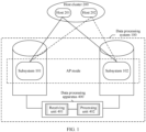
- FIG. 1 is a diagram of a structure of an example data processing system.
- the data processing system 100 may include a plurality of subsystems.
- FIG. 1 an example in which the data processing system 100 includes a subsystem 101 and a subsystem 102 is used for description. In actual application, the data processing system 100 may include more subsystems.
- the subsystem 101 belongs to a site (site) A.
- the subsystem 102 belongs to a site B.
- Each site may be configured to store a file provided by a tenant (or a tenant).
- Subsystems belonging to different sites may communicate with each other by using at least one of an internet protocol (internet protocol, IP), a remote direct data access (remote direct memory access, RDMA) protocol, or a fibre channel (fibre channel, FC), or may perform data communication with each other in another manner. This is not limited in this embodiment.
- IP internet protocol
- RDMA remote direct data access
- FC fibre channel
- Each subsystem may include one or more devices, and is configured to provide a corresponding data computing or storage capability.
- each subsystem includes a plurality of computing devices, a plurality of storage devices, or both a computing device and a storage device.
- the plurality of subsystems in the data processing system 100 may be specifically a plurality of storage arrays, and may be configured to support a service of a data storage type, a service of a data read type, or the like requested by the host.
- the plurality of subsystems in the data processing system 100 may be different storage domains in a same storage array, for example, may be storage domains divided by tenant, or storage domains (a file domain, a block domain, an object domain, or the like) divided by service.
- the subsystem 101 and the subsystem 102 in the data processing system 100 may run in an AP mode, and provide a service, for example, a data storage service or a data computing service, for a host 201 in a host cluster 200.
- a host 202 in the host cluster 200 may be used for disaster recovery of the host 201.
- requirements of the host 201 and the host 202 for a working mode of the data processing system 100 may change.
- a tenant P may expect the data processing system 100 to run in the AP mode, for example, only one subsystem in the data processing system 100 is allowed to perform data communication with the host 201 of the tenant P.
- the tenant P may require the data processing system 100 to run in an active-active (active-active, AA) mode, so that the host 201 and the host 202 that are of the tenant P and that are respectively active and standby can request the service and the like from the data processing system.
- active-active active-active
- the data processing system 100 supports only running in the AP mode, it is difficult to adapt to a change in a requirement of the tenant P for the working mode of the data processing system 100.
- the data processing system 100 supports only running in the AA mode, when the tenant P requires that the working mode of the data processing system 100 be the AP mode, it is also difficult to adapt to a change in a requirement of the tenant P for the working mode of the data processing system 100.
- a data processing apparatus 400 may be configured in the data processing system 100 shown in FIG. 1 .
- the data processing apparatus 400 includes a receiving unit 401 and a processing unit 402.
- the data processing apparatus may communicate with the subsystem 101 and the subsystem 102.
- the receiving unit 401 may receive a configuration instruction that may be delivered by, for example, the tenant or an administrator, and provide the configuration instruction for the processing unit 402. Therefore, the processing unit 402 may switch the working mode between the subsystem 101 and the subsystem 102 between the AP mode and the AA mode according to the configuration instruction.
- the data processing system 100 may automatically switch the working mode between the subsystem 101 and the subsystem 102 based on a change in the requirement of the host of the tenant, so that the data processing system 100 can adapt to the change in the requirement of the host of the tenant, and experience of the tenant in using the data processing system 100 can be improved.
- the data processing system 100 may be, for example, a system that provides a storage service, a system that provides a computing service, or a system of another type.
- a data storage system as an example to describe in detail a process in which the data storage system separately runs in the AP mode and in the AA mode to provide a service for the host.
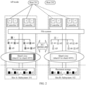
- FIG. 2 is a diagram in which a subsystem in the data storage system 100 runs in the AP mode according to an embodiment of this application.
- the subsystem 101 belonging to the site A may include one or more controllers.
- the controller may provide a plurality of ports externally, to communicate with the host 201 in the host cluster 200 through the plurality of ports.
- a controller 0 may provide a port 0 and a port 1
- a controller 1 may provide a port 2 and a port 3.
- the subsystem 101 may perform data communication with the host 201 through the port 0 and the port 2, for example, receive a service request delivered by the host 201.
- any quantity of ports in the subsystem 101 may be allocated to the host 201. This is not limited in this embodiment.
- the subsystem 102 belonging to the site B includes a controller 2 and a controller 3.
- a port 0' of the controller 2 and a port 2' of the controller 3 may be allocated to the host 201, so that when the subsystem 101 is faulty, the host 201 may access the subsystem 102 based on the port 0' or the port 2'.
- the host cluster 200 may further include the host 202.
- the host 202 may be used as a hot backup (that is, an online backup) of the host 201.
- the port 0 of the controller 0 and the port 2 of the controller 1 in the subsystem 101 may be allocated to the host 202.
- the host 202 when the host 201 is faulty, the host 202 continues to access the subsystem 101 through the port 0 and the port 2, to take over a service on the host 201. Therefore, reliability of the service on the host is improved.
- the port 0' of the controller 2 and the port 2' of the controller 3 in the subsystem 102 may be further allocated to the host 202, so that when the subsystem 101 is faulty, the host 202 can access the subsystem 102 through the port 0' or the port 2'.
- the site A may serve as a primary site that provides a service for the host 201, and the host 201 can only request the site A to provide the service.
- a file system (file system, FS) may be set in the subsystem 101 included in the site A.
- the file system has a root directory.
- the root directory may be stored in a memory of the subsystem 101.
- the subsystem 101 may mount the file system to the host 201, and provide the root directory of the file system for the host 201. In this way, the host 201 may access the file system in the subsystem 101 based on the root directory of the file system, and read data in the file system.
- the subsystem 101 may create a subdirectory in the root directory, and store, in the subdirectory by using a file format, the data provided by the host 201.
- the subsystem 101 may be configured with a plurality of IP addresses.
- the subsystem 101 may select one or more of the plurality of IP addresses, and allocate the one or more IP addresses to the host 201, so that the host 201 may access the file system in the subsystem 101 based on the the one or more allocated IP address.
- each IP address may be used to access all files in each subdirectory in the file system, and may support the host 201 in creating a subdirectory in the file system, to subsequently store a file in the subdirectory. For example, the host 201 creates a subdirectory d5 in the file system by using an allocated IP address 1, and creates a subdirectory d7 in the file system by using an allocated IP address 2.
- a preset quantity of shards may be configured in the subsystem 101.
- 4096 shards that is, a shard 0 to a shard 4095
- shards are used to store directories and files of the file system in different physical nodes in the subsystem in a distributed manner, and may be used to control data distribution and access.
- Each physical node may be configured to store data of one or more shards.
- a shard view (or a data distribution view) may be generated.
- the shard view may indicate distribution of data on different physical nodes.
- the subsystem 101 may periodically perform persistent storage on data in the memory.
- the data in the memory for example, the directory, the file, and the shard view, may be delivered to a persistent storage medium for storage, and a corresponding controller supports data reading and writing on the persistent storage medium.
- the subsystem 101 may continue to receive, based on released memory space, new data written by the host 201.
- the subsystem 102 included in the site B, for disaster recovery of the subsystem 101 may also be configured with a file system.
- data including the directory, the file in the directory, the shard view, and the like
- the tenant may configure an IP address for the host 201 to access the subsystem 102.
- FIG. 3 is a diagram of continuing to provide the service by the subsystem 102 after the subsystem 101 is faulty.
- the subsystem 102 may periodically monitor a heartbeat of the subsystem 101. Specifically, the subsystem 102 may receive a heartbeat message sent by the subsystem 101. When a time interval from time at which the subsystem 102 receives a heartbeat message from the subsystem 101 last time exceeds a preset interval, the subsystem 102 may determine that the subsystem 101 is faulty. Alternatively, the subsystem 102 may determine, after receiving a notification message sent by a quorum server (not shown in FIG. 3 ), that the subsystem 101 is faulty. This is not limited in this embodiment.
- the subsystem 102 may float an IP address used by the host 201 to access the subsystem 101 to the subsystem 102, and enable the port 0' or the port 2' that is allocated to the host 201 and that is used to support the host 201 in accessing the subsystem 102, so that the host 201 can access the data in the subsystem 102 based on the IP address and the ports.
- the subsystem 101 runs normally, in a process of providing the service for the host 201, not only generated new data is stored locally, but also the new data is synchronized to the subsystem 102. Therefore, data in a memory and a persistent storage medium of the subsystem 102 may be consistent with the data in the memory and the persistent storage medium of the subsystem 101. Therefore, the subsystem 102 may continue to provide the service for the host 201 based on the data.
- FIG. 2 and FIG. 3 mainly describe an implementation in which the subsystem 101 and the subsystem 102 in the data processing system 100 run in the AP mode and perform disaster recovery.
- the following describes an implementation in which the subsystem 101 and the subsystem 102 in the data processing system 100 run in the AP mode and perform disaster recovery.
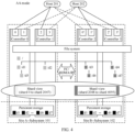
- FIG. 4 is a diagram in which a subsystem in the data storage system 100 runs in the AA mode according to an embodiment of this application.
- the subsystem 101 belonging to the site A may include one or more controllers.
- the controller may provide a plurality of ports externally, to communicate with the host 201 in the host cluster 200 through the plurality of ports.
- a controller 0 may provide a port 0 and a port 1
- a controller 1 may provide a port 2 and a port 3.
- the subsystem 101 may perform data communication with the host 201 through the port 0 and the port 2, for example, receive a service request delivered by the host 201.
- the subsystem 102 belonging to the site B includes a controller 2 and a controller 3.
- a port 1' of the controller 2 and a port 3' of the controller 3 perform data communication with the host 202 in the host cluster 200.
- the host 202 may be used as a hot backup (that is, an online backup) of the host 201, and is configured to improve reliability of a service on the host.
- the port 0' and the port 2' in the subsystem 102 may be further allocated to the host 201, so that when the subsystem 101 is faulty, the host 201 accesses the subsystem 102 through the port 0' and the port 2' to continue to request the service.
- the port 1 and the port 3 in the subsystem 101 may be further allocated to the host 202, so that when the subsystem 102 is faulty, the host 202 accesses the subsystem 101 through the port 1 and the port 3 to continue to request the service.
- both the host 201 and the host 202 may request sites to provide services. Specifically, the host 201 may request the site A to provide a service, and the host 202 may request the site B to provide a service. In this way, when the subsystem 102 for disaster recovery is used to meet a disaster recovery requirement, the subsystem 102 provides some services for the host. Therefore, an overall service capability and system resource utilization of the data processing system 100 can be improved.
- a file system may be set in the subsystem 101 included in the site A.
- the file system has a root directory.
- the root directory may be stored in a memory of the subsystem 101.
- the subsystem 101 may mount the file system to the host 201, and provide the root directory of the file system for the host 201. In this way, the host 201 may access the file system in the subsystem 101 based on the root directory of the file system, and read data in the file system.
- the subsystem 101 may create a subdirectory in the root directory, and store, in the subdirectory by using a file format, the data provided by the host 201.
- a file system is also set in the subsystem 102 in the site B.
- the file system in the subsystem 102 may have a same root directory as the file system in the subsystem 101.
- the host 202 may access the file system in the subsystem 101, and read and write data in the file system.
- a same plurality of IP addresses may be allocated to the host 201 and the host 202.
- the plurality of IP addresses are used to support the host 201/the host 202 in accessing all files in each subdirectory of the file system, and a corresponding directory may be created in the file system, so that a file is subsequently stored in the created subdirectory.
- the host 201 may create a subdirectory d5 in the file system by using an allocated IP address a
- the host 202 may create a subdirectory d7 in the file system by using an allocated IP address b.
- home sites of the host 201 and the host 202 may be further configured.
- the host 201 is configured to belong to the site A
- the host 202 is configured to belong to the site B.
- the host 201 and the host 202 preferentially access data in file systems of the home sites respectively, to avoid data transmission between different sites for files that the hosts request to access.
- some IP addresses are in a working state on the two sites respectively.
- Different shards may be configured in the subsystem 101 and the subsystem 102. As shown in FIG. 4 , 2048 shards are configured in each of the subsystem 101 and the subsystem 102.
- the shards in the subsystem 101 are shards 0 to 2047, and the shards in the subsystem 102 are shards 2048 to 4095.
- These shards are used to store directories and files of the file system in different physical nodes in the subsystems in a distributed manner, and may be used to control data distribution and access.
- Each physical node may be configured to store data of one or more shards. Based on data distribution of a plurality of shards, a shard view may be generated.
- the shard view may indicate distribution of data on different physical nodes.
- the shard views may be evenly distributed in the subsystem 101 and the subsystem 102 .
- the shard views may not be evenly distributed in the two subsystems.
- the subsystem 101 and the subsystem 102 may periodically perform persistent storage on data in memories. Since the subsystem 101 and the subsystem 102 separately store data in a part of the shard view, before persistent storage is performed on the data in the memories, the subsystem 101 may send data in the shard 0 to the shard 2047 to the subsystem 102, and the subsystem 102 may send data in the shard 2048 to the shard 4095 to the subsystem 101. In this way, both the subsystem 101 and the subsystem 102 can obtain complete data of the 4096 shards.
- the subsystem 101 and the subsystem 102 may separately deliver the data (data such as complete directories, files, and the shard view) in all the shards to persistent storage media for storage, and corresponding controllers support data reading and writing on the persistent storage media. In this way, the subsystem 101 and the subsystem 102 may continue to receive, based on released memory space, new data written by the host 201 and the host 202.
- the subsystem 101 or the subsystem 102 may be faulty in a running process.
- the other subsystem that runs normally may take over a service on the faulty subsystem.
- An example in which the subsystem 101 in the site A is faulty is used.
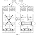
- FIG. 5 is a diagram of continuing to provide the service by the subsystem 102.
- the subsystem 101 and the subsystem 102 may monitor a heartbeat of each other at the same time.
- a time interval from time at which the subsystem 102 receives a heartbeat message from the subsystem 101 last time usually exceeds a preset interval.
- the subsystem 102 may determine that the subsystem 101 is faulty.
- the subsystem 101 may determine, after receiving a notification message sent by a quorum server (not shown in FIG. 5 ), that the subsystem 101 is faulty. This is not limited in this embodiment.
- the subsystem 102 may require the subsystem 101 to provide the data in the shard 0 to the shard 2047 stored in the memory to the subsystem 102. In this way, the shard view in the subsystem 102 may be updated to the shard 0 to the shard 4095.
- the subsystem 102 may float an IP address used by the host 201 to access the subsystem 101 to the subsystem 102, and enable the port 0' and the port 2' to receive a service request delivered by the host 201. In this way, when the host 201 requests to access a file in the file system, the subsystem 102 may feed back, to the host 201, the corresponding file stored in the shard 0 to the shard 4095, to continue to provide the service for the host 201.
- the subsystem 101 and the subsystem 102 in the data processing system 100 support switching of the working mode between the AP mode and the AA mode, to meet the requirement of the host cluster for the working mode between the subsystem 101 and the subsystem 102, and improve universality of the data processing system 100 in providing services.
- the data processing system 100 may support switching of the working mode between the subsystem 101 and the subsystem 102 from the AP mode to the AA mode, and may switch from the AA mode to the AP mode.
- the data processing apparatus 400 in the data processing system 100 may switch the working mode between the subsystem 101 and the subsystem 102.
- the receiving unit 401 may receive the configuration instruction.
- the configuration instruction is used to instruct the data processing apparatus 400 to switch the working mode between the subsystem 101 and the subsystem 102 from the AP mode to the AA mode or from the AA mode to the AP mode.
- the data processing apparatus 400 may externally provide a client, so that when determining that the working mode between the subsystem 101 and the subsystem 102 needs to be switched, the tenant or the administrator delivers the configuration instruction to the data processing apparatus 400 through the client, to instruct the data processing apparatus 400 to switch the working mode between the subsystem 101 and the subsystem 102 from a current mode to another mode.
- the receiving unit 401 receives the configuration instruction.
- the subsystem 101 and the subsystem 102 when a host using the full-cross networking mode is connected to the data processing system 100, the subsystem 101 and the subsystem 102 generally run in the AA mode to provide a corresponding service for the host.
- the networking mode of the host may also be another mode. This is not limited in this embodiment.
- the receiving unit may obtain the configuration instruction in another manner. This is not limited in this embodiment.
- the receiving unit 401 may send the configuration instruction to the processing unit 402, so that the processing unit 402 performs an operation of switching the working mode between the subsystem 101 and the subsystem 102.
- FIG. 6 is a diagram of switching the working mode between the subsystem 101 and the subsystem 102 from the AP mode to the AA mode.
- the processing unit 402 may indicate the subsystem 102 in the site B to allocate the port 1' of the controller 2 and the port 3' of the controller 3 to the host 202, so that the host 202 may access the file system in the subsystem 102 through the port 1' or the port 3'.
- the processing unit 402 may indicate the subsystem 101 to migrate data in some shards to the subsystem 102, and update the shard views in the subsystem 101 and the subsystem 102 respectively. For example, if the subsystem 101 migrates data in the shard 2048 to the shard 4095 to the subsystem 102, updated shard views in the subsystem 101 and the subsystem 102 are shown in FIG. 6 .
- the processing unit 402 may indicate the subsystem 102 to allocate, to the host 202, an IP address for accessing a file in a subdirectory. Further, the subsystem 102 may further specify the site B as the home site of the host 202. In this way, when accessing the file in the subdirectory (for example, accessing files in subdirectories d6 and d7), the host 202 may preferentially access the subsystem 102 in the site B to which the host 202 belongs, and may obtain data required by the host 202 from the subsystem 102 based on the shard view (for example, the shard 2048 to the shard 4095) in the subsystem 102.
- the shard view for example, the shard 2048 to the shard 4095
- the subsystem 101 may specify the site A as the home site of the host 201, so that the host 201 preferentially accesses the subsystem 101 in the site A.
- the working mode between the subsystem 101 and the subsystem 102 can be switched from the AP mode to the AA mode.
- FIG. 7 is a diagram of switching the working mode between the subsystem 101 and the subsystem 102 from the AA mode to the AP mode.
- the processing unit 402 may indicate the subsystem 102 in the site B to allocate the port 0' and the port 2' to the host 201, so that when the subsystem 101 is faulty, the host 201 may access the file system in the subsystem 102 through the port 0' or the port 2'.
- the data processing system 100 supports only the host 201 in requesting a service from a site. Therefore, the subsystem 102 may disable an IP address that is previously allocated to the host 202 and that is used to access the file in the subdirectory.
- the processing unit 402 may indicate the subsystem 101 to back up the data in all the shards to the subsystem 102, the subsystem 102 may back up the data in all the shards to the subsystem 101, and the shard views are updated in the subsystem 101 and the subsystem 102 respectively.
- the shards in the subsystem 101 and the subsystem 102 are a shard 0 to a shard 2047 and a shard 2048 to shard 4095 respectively.
- updated shard views in the subsystem 101 and the subsystem 102 are shown in FIG. 7 .
- a working mode between different subsystems in the data processing system 100 can be flexibly switched between the AP mode and the AA mode, to meet a requirement of an actual application scenario.
- the subsystem 101 and the subsystem 102 may run in the AP mode to provide the service corresponding to the AP mode for the host 201 and the host 202 in the host cluster 200.
- the subsystem 103 and the subsystem 104 may run in the AA mode to provide the service corresponding to the AA mode for the host 301 and the host 302 in the host cluster 300.
- the data processing system 100 shown in FIG. 2 to FIG. 9 is described by using an example in which the data storage service is provided for the tenant and the data storage service is specifically a file storage service. That is, data stored in the data processing system 100 may be stored in a form of a file.
- the data storage service provided by the data processing system 100 may be a block storage service or an object storage service.
- the block storage service means that when storing the data, the data processing system 100 divides the data into blocks according to a fixed size. A data volume of each block may be, for example, 512 bytes or 4 kilobytes (KB).
- the object storage service means that the data processing system 100 stores the data as an object (object).
- the object may be a basic unit for data storage in the data processing system 100.
- Each object may be a combination of data and a data attribute.
- the data attribute may be set based on an application requirement, including data distribution, quality of service, and the like.
- the data processing system 100 may also provide another type of service, for example, a data computing service like a model training service or a data statistics service. This is not limited in this embodiment.
- the data processing system 100 shown in FIG. 1 to FIG. 9 is applicable to a centralized storage application scenario or a distributed storage application scenario.
- data in each subsystem may be stored on a plurality of independent storage nodes in a distributed manner.
- the computing node may be integrated with a storage device, so that the computing node has both a computing capability and a storage capability, and a virtual machine may be created on the computing node, or a virtual machine may not be created on the computing node.
- a storage and computing separate architecture may be used between the computing node and a storage device, that is, the computing node and the storage device are independently deployed and communicate with each other through a network.
- the storage device may include one or more different storage media. This is not limited in this embodiment.
- the administrator may configure, based on the requirement of the tenant, the host of the tenant to be connected to a subsystem running in the AP mode, or to be connected to a subsystem running in the AA mode.
- the data processing system 100 may automatically connect the host to a proper subsystem based on the networking mode of the host.
- FIG. 10 is a schematic flowchart of a data processing method according to an embodiment of this application.
- the method may be applied to the data processing system 100 shown in FIG. 1 , FIG. 8 , or FIG. 9 .
- the method may also be applied to another data processing system to which the method is applicable.
- the following uses an example in which the method is applied to the data processing system 100 shown in FIG. 8 for description.
- the method may specifically include the following steps.
- the receiving unit 401 obtains a networking form of a host connected to the data processing system 100.
- the networking form of the host may be parallel networking, full-cross networking, or the like, or may be another type of networking mode.
- Parallel networking means that no cross connection may be established between different hosts in a network, for example, a data communication channel may not be directly established between the different hosts.
- Full-cross networking means that a connection may be established between the different hosts in the network, so that the different hosts may perform data communication with each other through the communication connection.
- S903 When the networking form of the host is full-cross networking, the processing unit 402 processes, by using the subsystem 103 and the subsystem 104 in the data processing system 100, a service requested by the host, where a working mode between the subsystem 103 and the subsystem 104 is an AA mode.
- a host whose networking form is parallel networking may be connected to the subsystem 101 that runs in the AP mode, and an access port and an IP address on the subsystem 102 may be automatically configured for the host, so that after the subsystem 101 is faulty, the host may access the subsystem 102, to implement uninterrupted service processing.
- the working mode of the subsystem to which the host is connected may be automatically switched.
- the subsystem 101 may automatically switch the working modes between the subsystems 101 and the subsystem 102 to the AA mode based on the manner shown in FIG. 6 , to meet an actual application requirement of the host.
- the process of switching the working mode may be automatically performed by the subsystem to which the host is connected.
- the working mode of the subsystem may be automatically switched under control of a quorum server or another device. This is not limited in this embodiment.
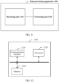
- an embodiment of this application further provides a data processing apparatus.
- the data processing apparatus 1100 is used in a data processing system, for example, the data processing system 100 shown in FIG. 1 to FIG. 10 .
- the data processing system includes a first subsystem and a second subsystem, for example, the subsystem 101 and the subsystem 102.
- the data processing apparatus 100 shown in FIG. 11 includes:
- the receiving unit 1101 is specifically configured to detect that a networking mode of the host connected to the data processing system is switched from a first networking mode to a second networking mode.
- the first networking mode is one of a parallel networking mode and a full-cross networking mode
- the second networking mode is the other of the parallel networking mode and the full-cross networking mode
- the data processing system further includes a third subsystem and a fourth subsystem.
- the third subsystem and the fourth subsystem work in the first mode.
- the first subsystem and the third subsystem belong to a first site
- the second subsystem and the fourth subsystem belong to a second site.
- the first subsystem and the second subsystem are configured to provide a data storage service for the target tenant.
- the first subsystem includes at least one storage array.
- the data storage service provided by the first subsystem and the second subsystem is a file storage service.
- the data storage service provided by the first subsystem and the second subsystem is a block storage service.
- the data processing apparatus 1100 shown in FIG. 11 corresponds to the data processing apparatus 400 in the foregoing embodiment. Therefore, for specific implementation technical effects of the data processing apparatus 1100, refer to related descriptions in the foregoing embodiment. Details are not described herein again.
- the computing device 1200 may include a communication interface 1210 and a processor 1220.
- the computing device 1200 may further include a memory 1230.
- the memory 1230 may be disposed inside the computing device 1200, or may be disposed outside the computing device 1200.
- all actions performed by the data processing apparatus 400 in the embodiments shown in FIG. 1 to FIG. 10 may be implemented by the processor 1220.
- the processor 1220 may obtain a configuration instruction through the communication interface 1210, and is configured to implement the method in FIG. 9 .
- steps of a processing procedure may be performed by a hardware integrated logic circuit of the processor 1220 or by instructions in a form of software, to complete the method in FIG. 9 .
- Program code executed by the processor 1220 to implement the foregoing method may be stored in the memory 1230.
- the memory 1230 is connected, for example, coupled, to the processor 1220.
- Some features in this embodiment of this application may be implemented/supported by the processor 1220 by executing program instructions or software code in the memory 1230.
- Software components loaded to the memory 1230 may be summarized in terms of functions or logic, for example, the processing unit 1102 shown in FIG. 11 .
- a function of the receiving unit 1101 may be implemented by the communication interface 1210.
- the processor may be a general-purpose processor, a digital signal processor, an application-specific integrated circuit, a field programmable gate array or another programmable logic device, a discrete gate or transistor logic device, or a discrete hardware component, and can implement or perform the methods, steps, and logical block diagrams disclosed in embodiments of this application.
- the general-purpose processor may be a microprocessor, any conventional processor, or the like. The steps of the method disclosed with reference to embodiments of this application may be directly performed by a hardware processor, or may be performed by a combination of hardware and software units in the processor.
- coupling is indirect coupling or a communication connection between apparatuses, units, or units, may be in electrical, mechanical or other forms, and is used for information exchange between apparatuses, units, or units.
- the processor may perform an operation in collaboration with the memory.
- the memory may be a nonvolatile memory, for example, a hard disk drive or a solid state drive, or may be a volatile memory, for example, a random access memory.
- the memory is, but not limited to, any other medium that can carry or store expected program code in a form of an instruction or a data structure and that can be accessed by a computer.
- a specific connection medium between the communication interface, the processor, and the memory is not limited in this embodiment of this application.
- the memory, the processor, and the communication interface may be connected through a bus.
- the bus may be classified as an address bus, a data bus, a control bus, and the like.
- an embodiment of this application further provides a computer storage medium.
- the storage medium stores a software program.
- the software program is read and executed by one or more processors, the method performed by the data processing apparatus 400 provided in any one or more of the foregoing embodiments may be implemented.
- the computer storage medium may include any medium capable of storing program code, for example, a USB flash drive, a removable hard disk, a read-only memory, a random access memory, a magnetic disk, or an optical disc.
- this application may be provided as a method, a system, or a computer program product. Therefore, this application may use a form of hardware only embodiments, software only embodiments, or embodiments with a combination of software and hardware. In addition, this application may use a form of a computer program product that is implemented on one or more computer-usable storage media (including but not limited to a disk memory, a CD-ROM, an optical memory, and the like) that include computer-usable program code.
- computer-usable storage media including but not limited to a disk memory, a CD-ROM, an optical memory, and the like
- the computer program instructions may alternatively be loaded onto a computer or another programmable data processing device, so that a series of operations and steps are performed on the computer or the another programmable device, so that computer-implemented processing is generated. Therefore, the instructions executed on the computer or the another programmable device provide steps for implementing a specific function in one or more procedures in the flowcharts and/or in one or more blocks in the block diagrams.
Landscapes
- Engineering & Computer Science (AREA)
- Theoretical Computer Science (AREA)
- Physics & Mathematics (AREA)
- General Engineering & Computer Science (AREA)
- General Physics & Mathematics (AREA)
- Quality & Reliability (AREA)
- Software Systems (AREA)
- Human Computer Interaction (AREA)
- Databases & Information Systems (AREA)
- Data Mining & Analysis (AREA)
- Computer Networks & Wireless Communication (AREA)
- Signal Processing (AREA)
- Mathematical Physics (AREA)
- Information Retrieval, Db Structures And Fs Structures Therefor (AREA)
Applications Claiming Priority (3)
| Application Number | Priority Date | Filing Date | Title |
|---|---|---|---|
| CN202210715668 | 2022-06-22 | ||
| CN202211170871.9A CN117271205A (zh) | 2022-06-22 | 2022-09-23 | 数据处理系统、数据处理方法、装置及相关设备 |
| PCT/CN2023/087566 WO2023246241A1 (fr) | 2022-06-22 | 2023-04-11 | Système de traitement de données, procédé et appareil de traitement de données, et dispositif associé |
Publications (2)
| Publication Number | Publication Date |
|---|---|
| EP4528516A1 true EP4528516A1 (fr) | 2025-03-26 |
| EP4528516A4 EP4528516A4 (fr) | 2025-11-05 |
Family
ID=89199638
Family Applications (1)
| Application Number | Title | Priority Date | Filing Date |
|---|---|---|---|
| EP23825896.6A Pending EP4528516A4 (fr) | 2022-06-22 | 2023-04-11 | Système de traitement de données, procédé et appareil de traitement de données, et dispositif associé |
Country Status (4)
| Country | Link |
|---|---|
| US (1) | US20250119468A1 (fr) |
| EP (1) | EP4528516A4 (fr) |
| CN (1) | CN117271205A (fr) |
| WO (1) | WO2023246241A1 (fr) |
Family Cites Families (4)
| Publication number | Priority date | Publication date | Assignee | Title |
|---|---|---|---|---|
| US20070073828A1 (en) * | 2005-09-08 | 2007-03-29 | Rao Sudhir G | Apparatus, system, and method for link layer message transfer over a durable and shared medium |
| US10009215B1 (en) * | 2012-11-30 | 2018-06-26 | EMC IP Holding Company LLC | Active/passive mode enabler for active/active block IO distributed disk(s) |
| US9626212B2 (en) * | 2014-06-28 | 2017-04-18 | Vmware, Inc. | Live migration of virtual machines with memory state sharing |
| US10732888B1 (en) * | 2019-01-23 | 2020-08-04 | EMC IP Holding Company LLC | Seamless transitioning among replication modes in a storage system |
-
2022
- 2022-09-23 CN CN202211170871.9A patent/CN117271205A/zh active Pending
-
2023
- 2023-04-11 WO PCT/CN2023/087566 patent/WO2023246241A1/fr not_active Ceased
- 2023-04-11 EP EP23825896.6A patent/EP4528516A4/fr active Pending
-
2024
- 2024-12-18 US US18/986,169 patent/US20250119468A1/en active Pending
Also Published As
| Publication number | Publication date |
|---|---|
| EP4528516A4 (fr) | 2025-11-05 |
| CN117271205A (zh) | 2023-12-22 |
| WO2023246241A1 (fr) | 2023-12-28 |
| US20250119468A1 (en) | 2025-04-10 |
Similar Documents
| Publication | Publication Date | Title |
|---|---|---|
| US11966612B2 (en) | Solid-state disk (SSD) data migration | |
| US8838850B2 (en) | Cluster control protocol | |
| US11262916B2 (en) | Distributed storage system, data processing method, and storage node | |
| US10409508B2 (en) | Updating of pinned storage in flash based on changes to flash-to-disk capacity ratio | |
| US20160077996A1 (en) | Fibre Channel Storage Array Having Standby Controller With ALUA Standby Mode for Forwarding SCSI Commands | |
| US12032849B2 (en) | Distributed storage system and computer program product | |
| US11153173B1 (en) | Dynamically updating compute node location information in a distributed computing environment | |
| CN112202853B (zh) | 数据同步方法、系统、计算机设备和存储介质 | |
| CN113849136B (zh) | 一种基于国产平台的自动化fc块存储处理方法和系统 | |
| CN109842651A (zh) | 一种业务不间断的负载均衡方法和系统 | |
| JP2009237826A (ja) | ストレージシステム及びそのボリューム管理方法 | |
| CN120560594B (zh) | 存储集群、系统、数据处理方法、设备、介质以及产品 | |
| US11604712B2 (en) | Active-active architecture for distributed ISCSI target in hyper-converged storage | |
| CN111225003B (zh) | 一种nfs节点配置方法和装置 | |
| EP3495939B1 (fr) | Procédé et dispositif de stockage de données dans un système de stockage de blocs distribué et support de stockage lisible par ordinateur | |
| US20230205638A1 (en) | Active-active storage system and data processing method thereof | |
| US11579926B2 (en) | Processing rest API requests based on resource usage satisfying predetermined limits | |
| US8838768B2 (en) | Computer system and disk sharing method used thereby | |
| CN112083886B (zh) | 一种nas设备的存储管理方法、系统及装置 | |
| US20250119468A1 (en) | Data Processing System, Data Processing Method and Apparatus, and Related Device | |
| US20240126847A1 (en) | Authentication method and apparatus, and storage system | |
| US11971835B2 (en) | Techniques for creating connections in a network fabric | |
| JP7781976B1 (ja) | 情報処理システム及び方法 | |
| US20250110842A1 (en) | Computer system and operation management method | |
| CN117827115A (zh) | 基于nas的存储系统及管理方法、装置、设备、介质 |
Legal Events
| Date | Code | Title | Description |
|---|---|---|---|
| STAA | Information on the status of an ep patent application or granted ep patent |
Free format text: STATUS: THE INTERNATIONAL PUBLICATION HAS BEEN MADE |
|
| PUAI | Public reference made under article 153(3) epc to a published international application that has entered the european phase |
Free format text: ORIGINAL CODE: 0009012 |
|
| STAA | Information on the status of an ep patent application or granted ep patent |
Free format text: STATUS: REQUEST FOR EXAMINATION WAS MADE |
|
| 17P | Request for examination filed |
Effective date: 20241219 |
|
| AK | Designated contracting states |
Kind code of ref document: A1 Designated state(s): AL AT BE BG CH CY CZ DE DK EE ES FI FR GB GR HR HU IE IS IT LI LT LU LV MC ME MK MT NL NO PL PT RO RS SE SI SK SM TR |
|
| DAV | Request for validation of the european patent (deleted) | ||
| DAX | Request for extension of the european patent (deleted) | ||
| REG | Reference to a national code |
Ref country code: DE Ref legal event code: R079 Free format text: PREVIOUS MAIN CLASS: G06F0011140000 Ipc: G06F0011160000 |
|
| A4 | Supplementary search report drawn up and despatched |
Effective date: 20251008 |
|
| RIC1 | Information provided on ipc code assigned before grant |
Ipc: G06F 11/16 20060101AFI20251001BHEP Ipc: G06F 11/20 20060101ALI20251001BHEP Ipc: G06F 9/50 20060101ALI20251001BHEP Ipc: G06F 3/06 20060101ALI20251001BHEP |