EP4528677A1 - Procédé de perception environnementale à conduite autonome, support et véhicule - Google Patents
Procédé de perception environnementale à conduite autonome, support et véhicule Download PDFInfo
- Publication number
- EP4528677A1 EP4528677A1 EP23838704.7A EP23838704A EP4528677A1 EP 4528677 A1 EP4528677 A1 EP 4528677A1 EP 23838704 A EP23838704 A EP 23838704A EP 4528677 A1 EP4528677 A1 EP 4528677A1
- Authority
- EP
- European Patent Office
- Prior art keywords
- information
- target detection
- environmental perception
- perception
- detection information
- Prior art date
- Legal status (The legal status is an assumption and is not a legal conclusion. Google has not performed a legal analysis and makes no representation as to the accuracy of the status listed.)
- Pending
Links
Images


Classifications
-
- G—PHYSICS
- G06—COMPUTING OR CALCULATING; COUNTING
- G06V—IMAGE OR VIDEO RECOGNITION OR UNDERSTANDING
- G06V10/00—Arrangements for image or video recognition or understanding
- G06V10/70—Arrangements for image or video recognition or understanding using pattern recognition or machine learning
- G06V10/82—Arrangements for image or video recognition or understanding using pattern recognition or machine learning using neural networks
-
- G—PHYSICS
- G01—MEASURING; TESTING
- G01S—RADIO DIRECTION-FINDING; RADIO NAVIGATION; DETERMINING DISTANCE OR VELOCITY BY USE OF RADIO WAVES; LOCATING OR PRESENCE-DETECTING BY USE OF THE REFLECTION OR RERADIATION OF RADIO WAVES; ANALOGOUS ARRANGEMENTS USING OTHER WAVES
- G01S13/00—Systems using the reflection or reradiation of radio waves, e.g. radar systems; Analogous systems using reflection or reradiation of waves whose nature or wavelength is irrelevant or unspecified
- G01S13/86—Combinations of radar systems with non-radar systems, e.g. sonar, direction finder
- G01S13/865—Combination of radar systems with lidar systems
-
- G—PHYSICS
- G01—MEASURING; TESTING
- G01S—RADIO DIRECTION-FINDING; RADIO NAVIGATION; DETERMINING DISTANCE OR VELOCITY BY USE OF RADIO WAVES; LOCATING OR PRESENCE-DETECTING BY USE OF THE REFLECTION OR RERADIATION OF RADIO WAVES; ANALOGOUS ARRANGEMENTS USING OTHER WAVES
- G01S13/00—Systems using the reflection or reradiation of radio waves, e.g. radar systems; Analogous systems using reflection or reradiation of waves whose nature or wavelength is irrelevant or unspecified
- G01S13/86—Combinations of radar systems with non-radar systems, e.g. sonar, direction finder
- G01S13/867—Combination of radar systems with cameras
-
- G—PHYSICS
- G01—MEASURING; TESTING
- G01S—RADIO DIRECTION-FINDING; RADIO NAVIGATION; DETERMINING DISTANCE OR VELOCITY BY USE OF RADIO WAVES; LOCATING OR PRESENCE-DETECTING BY USE OF THE REFLECTION OR RERADIATION OF RADIO WAVES; ANALOGOUS ARRANGEMENTS USING OTHER WAVES
- G01S13/00—Systems using the reflection or reradiation of radio waves, e.g. radar systems; Analogous systems using reflection or reradiation of waves whose nature or wavelength is irrelevant or unspecified
- G01S13/88—Radar or analogous systems specially adapted for specific applications
- G01S13/93—Radar or analogous systems specially adapted for specific applications for anti-collision purposes
- G01S13/931—Radar or analogous systems specially adapted for specific applications for anti-collision purposes of land vehicles
-
- G—PHYSICS
- G01—MEASURING; TESTING
- G01S—RADIO DIRECTION-FINDING; RADIO NAVIGATION; DETERMINING DISTANCE OR VELOCITY BY USE OF RADIO WAVES; LOCATING OR PRESENCE-DETECTING BY USE OF THE REFLECTION OR RERADIATION OF RADIO WAVES; ANALOGOUS ARRANGEMENTS USING OTHER WAVES
- G01S17/00—Systems using the reflection or reradiation of electromagnetic waves other than radio waves, e.g. lidar systems
- G01S17/86—Combinations of lidar systems with systems other than lidar, radar or sonar, e.g. with direction finders
-
- G—PHYSICS
- G01—MEASURING; TESTING
- G01S—RADIO DIRECTION-FINDING; RADIO NAVIGATION; DETERMINING DISTANCE OR VELOCITY BY USE OF RADIO WAVES; LOCATING OR PRESENCE-DETECTING BY USE OF THE REFLECTION OR RERADIATION OF RADIO WAVES; ANALOGOUS ARRANGEMENTS USING OTHER WAVES
- G01S17/00—Systems using the reflection or reradiation of electromagnetic waves other than radio waves, e.g. lidar systems
- G01S17/88—Lidar systems specially adapted for specific applications
- G01S17/93—Lidar systems specially adapted for specific applications for anti-collision purposes
- G01S17/931—Lidar systems specially adapted for specific applications for anti-collision purposes of land vehicles
-
- G—PHYSICS
- G06—COMPUTING OR CALCULATING; COUNTING
- G06F—ELECTRIC DIGITAL DATA PROCESSING
- G06F18/00—Pattern recognition
- G06F18/20—Analysing
- G06F18/25—Fusion techniques
- G06F18/253—Fusion techniques of extracted features
-
- G—PHYSICS
- G06—COMPUTING OR CALCULATING; COUNTING
- G06V—IMAGE OR VIDEO RECOGNITION OR UNDERSTANDING
- G06V10/00—Arrangements for image or video recognition or understanding
- G06V10/70—Arrangements for image or video recognition or understanding using pattern recognition or machine learning
- G06V10/77—Processing image or video features in feature spaces; using data integration or data reduction, e.g. principal component analysis [PCA] or independent component analysis [ICA] or self-organising maps [SOM]; Blind source separation
- G06V10/80—Fusion, i.e. combining data from various sources at the sensor level, preprocessing level, feature extraction level or classification level
- G06V10/803—Fusion, i.e. combining data from various sources at the sensor level, preprocessing level, feature extraction level or classification level of input or preprocessed data
-
- G—PHYSICS
- G06—COMPUTING OR CALCULATING; COUNTING
- G06V—IMAGE OR VIDEO RECOGNITION OR UNDERSTANDING
- G06V10/00—Arrangements for image or video recognition or understanding
- G06V10/70—Arrangements for image or video recognition or understanding using pattern recognition or machine learning
- G06V10/77—Processing image or video features in feature spaces; using data integration or data reduction, e.g. principal component analysis [PCA] or independent component analysis [ICA] or self-organising maps [SOM]; Blind source separation
- G06V10/80—Fusion, i.e. combining data from various sources at the sensor level, preprocessing level, feature extraction level or classification level
- G06V10/806—Fusion, i.e. combining data from various sources at the sensor level, preprocessing level, feature extraction level or classification level of extracted features
-
- G—PHYSICS
- G06—COMPUTING OR CALCULATING; COUNTING
- G06V—IMAGE OR VIDEO RECOGNITION OR UNDERSTANDING
- G06V20/00—Scenes; Scene-specific elements
- G06V20/50—Context or environment of the image
- G06V20/56—Context or environment of the image exterior to a vehicle by using sensors mounted on the vehicle
- G06V20/58—Recognition of moving objects or obstacles, e.g. vehicles or pedestrians; Recognition of traffic objects, e.g. traffic signs, traffic lights or roads
Definitions
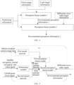
- the invention provides an environmental perception method for autonomous driving, the method including: obtaining first target detection information based on image data from a camera; obtaining second target detection information based on point cloud data from a LiDAR; obtaining positioning information based on positioning data from a positioning sensor, where the positioning information includes relative positioning information and global positioning information; fusing the first target detection information, the second target detection information, and the relative positioning information, to obtain first environmental perception information; and fusing the first environmental perception information, the relative positioning information, and the global positioning information, to obtain second environmental perception information.
- the method further includes obtaining third target detection information based on point cloud data from a millimeter-wave radar; and the fusing the first environmental perception information, the relative positioning information, and the global positioning information, to obtain second environmental perception information includes: fusing the first environmental perception information, the third target detection information, the relative positioning information, and the global positioning information, to obtain the second environmental perception information.
- the fusing the first target detection information, the second target detection information, and the relative positioning information, to obtain first environmental perception information includes: inputting the first target detection information, the second target detection information, and the relative positioning information into a first perception fusion model, to obtain the first environmental perception information; and the fusing the first environmental perception information, the relative positioning information, and the global positioning information, to obtain second environmental perception information includes: inputting the first environmental perception information, the relative positioning information, and the global positioning information into a second perception fusion model, to obtain the second environmental perception information.
- the first neural network and the positioning module are configured on a first system-on-chip, and the second neural network is configured on a second system-on-chip that is different from the first system-on-chip; or the first neural network is configured on a first system-on-chip, and the second neural network and the positioning module are configured on a second system-on-chip that is different from the first system-on-chip.
- the first perception fusion model and the second perception model are configured on the first system-on-chip.
- the inputting the first target detection information, the second target detection information, and the relative positioning information into a first perception fusion model, to obtain the first environmental perception information includes: inputting the first target detection information and the relative positioning information into the first perception fusion model, to obtain the first environmental perception information, if it is detected that the second system-on-chip is turned off.
- the first perception fusion model is configured on the first system-on-chip; and the second perception model is configured on the second system-on-chip.
- the inputting the first target detection information, the second target detection information, and the relative positioning information into the first perception fusion model, to obtain the first environmental perception information includes: inputting the first target detection information and the relative positioning information into the first perception fusion model, to obtain the first environmental perception information; and the method further includes: outputting the first environmental perception information as a final perception result.
- a system-on-chip in a second aspect, there is configured a system-on-chip.
- the system-on-chip includes at least one processor and a storage apparatus.
- the storage apparatus is configured to store a plurality of program codes, where the program codes are adapted to be loaded and executed by the at least one processor to perform the environmental perception method for autonomous driving described in any one of the foregoing aspects.
- a computer-readable storage medium stores a plurality of program codes, where the program codes are adapted to be loaded and executed by at least one processor to perform the environmental perception method for autonomous driving described in any one of the foregoing aspects.
- a vehicle including the system-on-chip described above.
- the one or more technical solutions of the invention described above have at least one or more of the following beneficial effects: according to the environmental perception method for autonomous driving in the invention, the first target detection information corresponding to the camera, the second target detection information corresponding to the LiDAR, and the positioning information corresponding to the positioning sensor are hierarchically fused, to obtain final environmental perception information.
- the system has independent environmental perception information output capabilities, allowing the system to operate normally, thereby improving the safety performance of the vehicle.
- a “module” or “processor” may include hardware, software, or a combination thereof.
- a module may include a hardware circuit, various suitable sensors, a communication port, and a memory, may include a software part, for example, program code, or may be a combination of software and hardware.
- the processor may be a central processing unit, a microprocessor, a graphics processing unit, a digital signal processor, or any other suitable processor.
- the processor has a data and/or signal processing function.
- the processor may be implemented in software, hardware, or a combination thereof.
- a non-transitory computer-readable storage medium includes any suitable medium that can store program code, for example, a magnetic disk, a hard disk, an optical disc, a flash memory, a read-only memory, or a random access memory.
- the term “A and/or B” indicates all possible combinations of A and B, for example, only A, only B, or A and B.
- the term “at least one A or B” or “at least one of A and B” has a meaning similar to “A and/or B" and may include only A, only B, or A and B.
- the terms “a/an” and “this” in the singular form may also include the plural form.
- a vehicle-mounted camera and a LiDAR are highly bound. Therefore, during the process of obtaining environmental perception information, it is required that image data collected by the vehicle-mounted camera, and point cloud data collected by the LiDAR be accurately transmitted to a fusion unit before being recognized to obtain final environmental perception information.
- image data collected by the vehicle-mounted camera, and point cloud data collected by the LiDAR be accurately transmitted to a fusion unit before being recognized to obtain final environmental perception information.
- the environmental perception information required by the vehicle cannot be obtained, so that safe driving of the vehicle cannot be ensured.
- the invention provides an environmental perception method for autonomous driving, a medium, and a vehicle.
- First target detection information corresponding to a camera, second target detection information corresponding to a LiDAR, and positioning information corresponding to a positioning sensor are hierarchically fused, so as to obtain final environmental perception information.
- the system has independent environmental perception information output capabilities, allowing the system to operate normally, thereby improving the safety performance of the vehicle.
- FIG. 1 is a schematic flowchart of main steps of an environmental perception method for autonomous driving according to an embodiment of the invention.
- the environmental perception method for autonomous driving in this embodiment of the invention mainly includes step S 101 to step S105 below.
- Step S101 Obtain first target detection information based on image data from a camera.
- the camera is used to collect image data of the surroundings of a vehicle.
- a plurality of cameras may be installed on the vehicle, and may include at least one long-range camera. Specific installation positions of the cameras are not limited, as long as the cameras can implement 360° coverage around the vehicle.
- the obtaining first target detection information based on image data from a camera includes: inputting the image data from the camera into a first neural network, to obtain the first target detection information, where the first target detection information includes at least one of obstacle information, traffic sign information, ground information, oncoming vehicle light information, and lane line information.
- the first neural network is capable of recognizing the image data of the camera, thereby obtaining information such as the obstacle information, the traffic sign information, the ground information, the oncoming vehicle light information, and the lane line information.
- the first neural network may be implemented based on any one of a FasterRCNN algorithm, a YOLO algorithm, and a Mobilenet algorithm, but is not limited thereto.
- Step S102 Obtain second target detection information based on point cloud data from a LiDAR.
- the obtaining second target detection information based on point cloud data from a LiDAR includes: inputting the point cloud data from the LiDAR into a second neural network, to obtain the second target detection information, where the second target detection information includes at least one of obstacle information and drivable area information.
- rasterization preprocessing may be performed on raw three-dimensional point cloud data. Rasterization preprocessing helps to reduce the network's dependence on absolute distances, improves the network's robustness to the distribution of LiDAR point clouds, and also improves the network's generalization ability.
- paired information of coordinates and features is obtained and is input into a sparse three-dimensional convolutional network.
- Feature extraction is performed on a three-dimensional shape composed of the point clouds by using the sparse three-dimensional convolutional network, to obtain higher-dimensional features.
- three-dimensional point cloud features are obtained.
- a feature map containing two-dimensional features is obtained by using a two-dimensional grid feature extraction network.
- a detection head After the feature map obtained through two-dimensional feature extraction is obtained, a detection result in the form of bbox is output by using a detection head network.
- a detection head outputs detection attributes of each pixel on the feature map after two layers of convolution, including classification scores, three-dimensional detection box attributes (coordinates, dimensions, and angles), and orientation classification attributes, etc.
- a point cloud detection network Due to the physical characteristics of the LiDAR, a point cloud detection network often tends to output some false targets, so it is necessary to perform post-processing on the preliminarily obtained detection result to filter out these false targets, to obtain a final three-dimensional detection result, which is the obstacle information.
- a ground height of a current environment is estimated based on the three-dimensional point cloud data collected by the LiDAR, then, non-ground point clouds in the three-dimensional point cloud data that does not belong to the ground are determined based on the ground height, then, obstacle detection is performed on the non-ground point clouds, to obtain one or more obstacles, and finally, the drivable area is determined based on a position of an obstacle.
- the obstacle information and the drivable area are obtained, so as to provide foundational support for subsequent information fusion.
- the positioning sensor includes at least one of satellite navigation, an inertial navigation device, and an odometer.
- positioning data from at least one of the satellite navigation, the inertial navigation device, and the odometer is input into a positioning module, to obtain current pose information of an autonomous vehicle relative to an initial pose, and global pose information of the autonomous vehicle on a global map, where the current pose information is the relative positioning information, and the global pose information is the global positioning information.
- Step S104 Fuse the first target detection information, the second target detection information, and the relative positioning information, to obtain first environmental perception information.
- the fusing the first target detection information, the second target detection information, and the relative positioning information, to obtain first environmental perception information includes: inputting the first target detection information, the second target detection information, and the relative positioning information into a first perception fusion model, to obtain the first environmental perception information.
- the first target detection information includes a two-dimensional bounding box for a detected target, and a first confidence value
- the second target detection information includes a candidate three-dimensional bounding box for the detected target, and a second confidence value.
- a manual feature is constructed by using the first target detection information, the second target detection information, and the relative positioning information, and then, the manual feature is input into a late-fusion network to generate a new confidence value for the candidate three-dimensional bounding box, to obtain the first environmental perception information.
- the constructing a manual feature by using the first target detection information, the second target detection information, and the relative positioning information includes: adding the first confidence value corresponding to the two-dimensional bounding box, and the second confidence value corresponding to the three-dimensional bounding box to the manual feature; projecting a three-dimensional bounding box corresponding to the LiDAR onto a camera image, to obtain a two-dimensional bounding box corresponding to the LiDAR; calculating a generalized intersection over union (GIoU) based on the two-dimensional bounding box corresponding to the LiDAR, and a two-dimensional bounding box corresponding to the camera, and adding the calculated GIoU to the manual feature; estimating a depth of a center point of a vehicle target based on the second target detection information, and adding the depth to the manual feature; and obtaining a distance from the three-dimensional bounding box to a center of the camera based on the relative positioning information, and adding the distance to the manual feature.
- GIoU generalized intersection over union
- GIoU IoU ⁇ A 3 / A 1 ⁇ A 2 A 3
- the late-fusion network is composed of one maximum pooling layer, and four one-dimensional convolutional networks, which are respectively Conv2D(4, 16, (1,1), 1), Conv2D(16, 32, (1,1), 1), Conv2D(32, 32, (1, 1), 1) and Conv2D(32, 1, (1,1), 1), where Conv2D(cin, cout, k, s) has the meaning of: cin and cout are numbers of input and output channels, respectively, k is a size of a convolution kernel, and s is a stride.
- the first perception fusion module may fuse the first target detection information, the second target detection information, and the relative positioning information, to obtain the first environmental perception information, thereby providing support for safe driving of the vehicle.
- the first perception fusion module may alternatively be implemented through other algorithms, and details are not described herein again.
- Step S105 Fuse the first environmental perception information, the relative positioning information, and the global positioning information, to obtain second environmental perception information.
- the fusing the first environmental perception information, the relative positioning information, and the global positioning information, to obtain second environmental perception information includes: inputting the first environmental perception information, the relative positioning information, and the global positioning information into a second perception fusion model, to obtain the second environmental perception information.
- an operation trajectory of a target is estimated based on the first environmental perception information, the relative positioning information, and the global positioning information, and information such as a specific position, speed magnitude, and direction of the target in the global map at a next moment is accurately estimated.
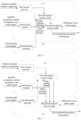
- the method further includes obtaining third target detection information based on point cloud data from a millimeter-wave radar; and the fusing the first environmental perception information, the relative positioning information, and the global positioning information, to obtain second environmental perception information includes: fusing the first environmental perception information, the third target detection information, the relative positioning information, and the global positioning information, to obtain the second environmental perception information.
- first, detection boxes for the first environmental perception information and the third target detection information are obtained, where the detection box is a smallest bounding box for the target.
- positions of targets in the first environmental perception information and the third target detection information, and trajectories and speeds of the targets are determined based on the relative positioning information and the global positioning information, and an IoU of detection boxes corresponding to two targets is calculated based on the positions.
- the IoU, a trajectory similarity, and a speed similarity meet a preset condition, specifically, if the IoU is greater than an IoU threshold, the trajectory similarity is greater than a trajectory threshold, and the speed similarity is greater than a speed similarity threshold, it indicates that matching of the two targets is successful.
- information such as the position, speed, and heading angle of the target contained in the first environmental perception information is output as the second perception information.
- the preset condition indicates that matching of the two targets is unsuccessful. Specifically, when an unsuccessfully matched target is a target in the first environmental perception information, information such as the position, speed, and heading angle of the target obtained from the first environmental perception information is output as specific information of the target. Specifically, when an unsuccessfully matched target is a target in the third target detection information, information such as the position, speed, and heading angle of the target obtained from the third target detection information is output as specific information of the target.
- the second perception fusion module may further fuse the relative positioning information, the global positioning information, the first environmental perception information, and the third target detection information, to obtain more accurate environmental perception information.
- the second perception fusion module may alternatively be implemented through other algorithms, and details are not described herein again.
- the first target detection information corresponding to the camera, the second target detection information corresponding to the LiDAR, and the positioning information corresponding to the positioning sensor are hierarchically fused, so as to obtain final environmental perception information.
- the system has independent environmental perception information output capabilities, allowing the system to operate normally, thereby improving the safety performance of the vehicle.
- the third target detection information obtained based on the point cloud data collected by the millimeter-wave radar may also be added to the process of environmental information fusion.
- the third target detection information, the first environmental perception information, the relative positioning information, and the global positioning information are input into the second perception fusion module for fusion, to obtain second environmental perception information. Since target detection information corresponding to the point clouds from the millimeter-wave radar is added to the fusion process, the second environmental perception information obtained through fusion is more accurate.
- the first neural network, the positioning module, the second neural network, the first perception fusion model, and the second perception fusion model may be configured on a system-on-chip (SOC).
- SOC system-on-chip
- the first perception fusion model and the second perception model are configured on the first system-on-chip.
- the first neural network and the positioning module are configured on a first system-on-chip (SOC1), and the second neural network is configured on a second system-on-chip (SOC2) that is different from SOC1.
- SOC1 system-on-chip
- SOC2 second system-on-chip
- the first neural network may be on the first system-on-chip (SOC1)
- the second neural network and the positioning module are configured on the second system-on-chip (SOC2).
- the computer program may be stored in a computer-readable storage medium.
- the steps in the above method embodiments may be implemented.
- the computer program includes computer program code, and the computer program code may be in the form of source code, target code, and an executable file, or in some intermediate forms, etc.
- the computer-readable storage medium may include: any entity or apparatus that can carry the computer program code, such as a medium, a USB flash drive, a removable hard disk, a magnetic disk, an optical disc, a computer memory, a read-only memory, a random access memory, an electric carrier signal, a telecommunications signal, and a software distribution medium.
- a medium such as a medium, a USB flash drive, a removable hard disk, a magnetic disk, an optical disc, a computer memory, a read-only memory, a random access memory, an electric carrier signal, a telecommunications signal, and a software distribution medium.
- the content included in the computer-readable storage medium may be appropriately added or deleted depending on requirements of the legislation and patent practice in a jurisdiction.
- the computer-readable storage medium does not include an electric carrier signal and a telecommunications signal.
- the invention further provides a system-on-chip.
- the system-on-chip includes a processor 80 and a storage apparatus 81.
- the storage apparatus may be configured to store a program for performing the environmental perception method for autonomous driving in the above method embodiment.
- the processor may be configured to execute a program in the storage apparatus.
- the program includes but is not limited to the program for performing the environmental perception method for autonomous driving in the above method embodiment. For ease of description, only parts related to the embodiments of the invention are shown. For specific technical details that are not disclosed, refer to the method part of the embodiments of the invention.
- the invention further provides a computer-readable storage medium.
- the computer-readable storage medium may be configured to store a program for performing the environmental perception method for autonomous driving in the above method embodiment, and the program may be loaded and executed by at least one processor to implement the environmental perception method for autonomous driving described above.
- the computer-readable storage medium may be a storage apparatus device formed by various electronic devices.
- the computer-readable storage medium in this embodiment of the invention is a non-transitory computer-readable storage medium.
- the invention further provides a vehicle, including the system-on-chip described above.
Landscapes
- Engineering & Computer Science (AREA)
- Physics & Mathematics (AREA)
- Theoretical Computer Science (AREA)
- General Physics & Mathematics (AREA)
- Radar, Positioning & Navigation (AREA)
- Remote Sensing (AREA)
- Computer Vision & Pattern Recognition (AREA)
- Evolutionary Computation (AREA)
- Multimedia (AREA)
- Artificial Intelligence (AREA)
- Computing Systems (AREA)
- Databases & Information Systems (AREA)
- General Health & Medical Sciences (AREA)
- Medical Informatics (AREA)
- Software Systems (AREA)
- Health & Medical Sciences (AREA)
- Computer Networks & Wireless Communication (AREA)
- Electromagnetism (AREA)
- Data Mining & Analysis (AREA)
- Life Sciences & Earth Sciences (AREA)
- Bioinformatics & Cheminformatics (AREA)
- Bioinformatics & Computational Biology (AREA)
- Evolutionary Biology (AREA)
- General Engineering & Computer Science (AREA)
- Traffic Control Systems (AREA)
Applications Claiming Priority (2)
| Application Number | Priority Date | Filing Date | Title |
|---|---|---|---|
| CN202210834143.7A CN115205803A (zh) | 2022-07-14 | 2022-07-14 | 自动驾驶环境感知方法、介质及车辆 |
| PCT/CN2023/103659 WO2024012211A1 (fr) | 2022-07-14 | 2023-06-29 | Procédé de perception environnementale à conduite autonome, support et véhicule |
Publications (2)
| Publication Number | Publication Date |
|---|---|
| EP4528677A1 true EP4528677A1 (fr) | 2025-03-26 |
| EP4528677A4 EP4528677A4 (fr) | 2025-09-03 |
Family
ID=83583028
Family Applications (1)
| Application Number | Title | Priority Date | Filing Date |
|---|---|---|---|
| EP23838704.7A Pending EP4528677A4 (fr) | 2022-07-14 | 2023-06-29 | Procédé de perception environnementale à conduite autonome, support et véhicule |
Country Status (3)
| Country | Link |
|---|---|
| EP (1) | EP4528677A4 (fr) |
| CN (1) | CN115205803A (fr) |
| WO (1) | WO2024012211A1 (fr) |
Families Citing this family (4)
| Publication number | Priority date | Publication date | Assignee | Title |
|---|---|---|---|---|
| CN115205803A (zh) * | 2022-07-14 | 2022-10-18 | 安徽蔚来智驾科技有限公司 | 自动驾驶环境感知方法、介质及车辆 |
| CN115690261B (zh) * | 2022-12-29 | 2023-04-14 | 安徽蔚来智驾科技有限公司 | 基于多传感器融合的车位建图方法、车辆及存储介质 |
| CN117163071B (zh) * | 2023-11-03 | 2024-03-05 | 安徽蔚来智驾科技有限公司 | 车辆控制方法、控制装置、可读存储介质及车辆 |
| CN118330666B (zh) * | 2024-04-11 | 2024-11-05 | 清华大学 | 基于激光雷达的智能网联公交多车编队感知方法及装置 |
Family Cites Families (11)
| Publication number | Priority date | Publication date | Assignee | Title |
|---|---|---|---|---|
| US10082797B2 (en) * | 2015-09-16 | 2018-09-25 | Ford Global Technologies, Llc | Vehicle radar perception and localization |
| CN109556615B (zh) * | 2018-10-10 | 2022-10-04 | 吉林大学 | 基于自动驾驶的多传感器融合认知的驾驶地图生成方法 |
| CN110032965B (zh) * | 2019-04-10 | 2023-06-27 | 南京理工大学 | 基于遥感图像的视觉定位方法 |
| US11532168B2 (en) * | 2019-11-15 | 2022-12-20 | Nvidia Corporation | Multi-view deep neural network for LiDAR perception |
| CN113002396B (zh) * | 2020-04-14 | 2022-06-10 | 青岛慧拓智能机器有限公司 | 一种用于自动驾驶矿用车辆的环境感知系统及矿用车辆 |
| US11691648B2 (en) * | 2020-07-24 | 2023-07-04 | SafeAI, Inc. | Drivable surface identification techniques |
| WO2022104774A1 (fr) * | 2020-11-23 | 2022-05-27 | 华为技术有限公司 | Procédé et appareil de détection de cible |
| CN113899363B (zh) * | 2021-09-29 | 2022-10-21 | 北京百度网讯科技有限公司 | 车辆的定位方法、装置及自动驾驶车辆 |
| CN113989545A (zh) * | 2021-10-11 | 2022-01-28 | 金钱猫科技股份有限公司 | 一种多源传感器数据融合方法、装置和存储设备 |
| CN115273027A (zh) * | 2022-07-14 | 2022-11-01 | 安徽蔚来智驾科技有限公司 | 环境感知方法、域控制器、存储介质及车辆 |
| CN115205803A (zh) * | 2022-07-14 | 2022-10-18 | 安徽蔚来智驾科技有限公司 | 自动驾驶环境感知方法、介质及车辆 |
-
2022
- 2022-07-14 CN CN202210834143.7A patent/CN115205803A/zh active Pending
-
2023
- 2023-06-29 WO PCT/CN2023/103659 patent/WO2024012211A1/fr not_active Ceased
- 2023-06-29 EP EP23838704.7A patent/EP4528677A4/fr active Pending
Also Published As
| Publication number | Publication date |
|---|---|
| WO2024012211A1 (fr) | 2024-01-18 |
| CN115205803A (zh) | 2022-10-18 |
| EP4528677A4 (fr) | 2025-09-03 |
Similar Documents
| Publication | Publication Date | Title |
|---|---|---|
| EP4528677A1 (fr) | Procédé de perception environnementale à conduite autonome, support et véhicule | |
| CN112417967B (zh) | 障碍物检测方法、装置、计算机设备和存储介质 | |
| EP3881226B1 (fr) | Classification d'objets à l'aide d'un contexte extra-régional | |
| EP4557241A1 (fr) | Procédé de perception environnementale, contrôleur de domaine, support de stockage et véhicule | |
| EP3361278B1 (fr) | Localisation de véhicule autonome basée sur une technique de projection de noyau de walsh | |
| CN111091037B (zh) | 用于确定驾驶信息的方法和设备 | |
| CN110632617B (zh) | 一种激光雷达点云数据处理的方法及装置 | |
| CN113469045B (zh) | 无人集卡的视觉定位方法、系统、电子设备和存储介质 | |
| CN111192295A (zh) | 目标检测与跟踪方法、相关设备和计算机可读存储介质 | |
| US20240221215A1 (en) | High-precision vehicle positioning | |
| US20210383213A1 (en) | Prediction device, prediction method, computer program product, and vehicle control system | |
| CN116052124B (zh) | 多相机生成局部地图模板理解加强目标检测方法及系统 | |
| US20250010854A1 (en) | Image processing method and apparatus, and storage medium | |
| US11105924B2 (en) | Object localization using machine learning | |
| US20250014355A1 (en) | Road obstacle detection method and apparatus, and device and storage medium | |
| WO2023036032A1 (fr) | Procédé et appareil de détection de ligne de voie | |
| CN112639822A (zh) | 一种数据处理方法及装置 | |
| CN114675274A (zh) | 障碍物检测方法、装置、存储介质及电子设备 | |
| CN115965929A (zh) | 一种基于点云的障碍物检测方法、装置和域控制器 | |
| CN116311114A (zh) | 一种可行驶区域生成方法、装置、电子设备及存储介质 | |
| CN114384486A (zh) | 一种数据处理方法及装置 | |
| US10796569B2 (en) | Vehicle determination apparatus, vehicle determination method, and computer readable medium | |
| Bernardi et al. | High integrity lane-level occupancy estimation of road obstacles through LiDAR and HD map data fusion | |
| CN119810792A (zh) | 多模态障碍物检测方法、装置、电子设备及存储介质 | |
| CN118535459A (zh) | 用于自动驾驶的路测方法及系统 |
Legal Events
| Date | Code | Title | Description |
|---|---|---|---|
| STAA | Information on the status of an ep patent application or granted ep patent |
Free format text: STATUS: THE INTERNATIONAL PUBLICATION HAS BEEN MADE |
|
| PUAI | Public reference made under article 153(3) epc to a published international application that has entered the european phase |
Free format text: ORIGINAL CODE: 0009012 |
|
| STAA | Information on the status of an ep patent application or granted ep patent |
Free format text: STATUS: REQUEST FOR EXAMINATION WAS MADE |
|
| 17P | Request for examination filed |
Effective date: 20241218 |
|
| AK | Designated contracting states |
Kind code of ref document: A1 Designated state(s): AL AT BE BG CH CY CZ DE DK EE ES FI FR GB GR HR HU IE IS IT LI LT LU LV MC ME MK MT NL NO PL PT RO RS SE SI SK SM TR |
|
| A4 | Supplementary search report drawn up and despatched |
Effective date: 20250805 |
|
| RIC1 | Information provided on ipc code assigned before grant |
Ipc: G06V 20/56 20220101AFI20250730BHEP Ipc: G06V 10/80 20220101ALI20250730BHEP Ipc: G06V 10/82 20220101ALI20250730BHEP Ipc: G06N 3/04 20230101ALI20250730BHEP Ipc: G01S 13/86 20060101ALI20250730BHEP Ipc: G01S 13/931 20200101ALI20250730BHEP Ipc: G01S 17/86 20200101ALI20250730BHEP Ipc: G01S 17/931 20200101ALI20250730BHEP |
|
| DAV | Request for validation of the european patent (deleted) | ||
| DAX | Request for extension of the european patent (deleted) | ||
| STAA | Information on the status of an ep patent application or granted ep patent |
Free format text: STATUS: EXAMINATION IS IN PROGRESS |
|
| 17Q | First examination report despatched |
Effective date: 20251029 |