EP4528779A1 - Structure de traction et de verrouillage de disjoncteur et disjoncteur enfichable - Google Patents
Structure de traction et de verrouillage de disjoncteur et disjoncteur enfichable Download PDFInfo
- Publication number
- EP4528779A1 EP4528779A1 EP23834936.9A EP23834936A EP4528779A1 EP 4528779 A1 EP4528779 A1 EP 4528779A1 EP 23834936 A EP23834936 A EP 23834936A EP 4528779 A1 EP4528779 A1 EP 4528779A1
- Authority
- EP
- European Patent Office
- Prior art keywords
- cover plate
- operating
- circuit breaker
- locking
- housing
- Prior art date
- Legal status (The legal status is an assumption and is not a legal conclusion. Google has not performed a legal analysis and makes no representation as to the accuracy of the status listed.)
- Pending
Links
Images





Classifications
-
- H—ELECTRICITY
- H01—ELECTRIC ELEMENTS
- H01H—ELECTRIC SWITCHES; RELAYS; SELECTORS; EMERGENCY PROTECTIVE DEVICES
- H01H9/00—Details of switching devices, not covered by groups H01H1/00 - H01H7/00
- H01H9/20—Interlocking, locking, or latching mechanisms
- H01H9/22—Interlocking, locking, or latching mechanisms for interlocking between casing, cover, or protective shutter and mechanism for operating contacts
- H01H9/223—Defeatable locking means
-
- H—ELECTRICITY
- H01—ELECTRIC ELEMENTS
- H01H—ELECTRIC SWITCHES; RELAYS; SELECTORS; EMERGENCY PROTECTIVE DEVICES
- H01H71/00—Details of the protective switches or relays covered by groups H01H73/00 - H01H83/00
- H01H71/02—Housings; Casings; Bases; Mountings
-
- H—ELECTRICITY
- H01—ELECTRIC ELEMENTS
- H01H—ELECTRIC SWITCHES; RELAYS; SELECTORS; EMERGENCY PROTECTIVE DEVICES
- H01H71/00—Details of the protective switches or relays covered by groups H01H73/00 - H01H83/00
- H01H71/02—Housings; Casings; Bases; Mountings
- H01H71/025—Constructional details of housings or casings not concerning the mounting or assembly of the different internal parts
-
- H—ELECTRICITY
- H01—ELECTRIC ELEMENTS
- H01H—ELECTRIC SWITCHES; RELAYS; SELECTORS; EMERGENCY PROTECTIVE DEVICES
- H01H71/00—Details of the protective switches or relays covered by groups H01H73/00 - H01H83/00
- H01H71/02—Housings; Casings; Bases; Mountings
- H01H71/0264—Mountings or coverplates for complete assembled circuit breakers, e.g. snap mounting in panel
-
- H—ELECTRICITY
- H01—ELECTRIC ELEMENTS
- H01H—ELECTRIC SWITCHES; RELAYS; SELECTORS; EMERGENCY PROTECTIVE DEVICES
- H01H71/00—Details of the protective switches or relays covered by groups H01H73/00 - H01H83/00
- H01H71/10—Operating or release mechanisms
-
- H—ELECTRICITY
- H01—ELECTRIC ELEMENTS
- H01H—ELECTRIC SWITCHES; RELAYS; SELECTORS; EMERGENCY PROTECTIVE DEVICES
- H01H73/00—Protective overload circuit-breaking switches in which excess current opens the contacts by automatic release of mechanical energy stored by previous operation of a hand reset mechanism
- H01H73/02—Details
- H01H73/06—Housings; Casings; Bases; Mountings
- H01H73/08—Plug-in housings
-
- H—ELECTRICITY
- H01—ELECTRIC ELEMENTS
- H01H—ELECTRIC SWITCHES; RELAYS; SELECTORS; EMERGENCY PROTECTIVE DEVICES
- H01H9/00—Details of switching devices, not covered by groups H01H1/00 - H01H7/00
- H01H9/20—Interlocking, locking, or latching mechanisms
-
- H—ELECTRICITY
- H01—ELECTRIC ELEMENTS
- H01H—ELECTRIC SWITCHES; RELAYS; SELECTORS; EMERGENCY PROTECTIVE DEVICES
- H01H9/00—Details of switching devices, not covered by groups H01H1/00 - H01H7/00
- H01H9/20—Interlocking, locking, or latching mechanisms
- H01H9/26—Interlocking, locking, or latching mechanisms for interlocking two or more switches
- H01H2009/265—Interlocking, locking, or latching mechanisms for interlocking two or more switches with interlocking of more than two switches
-
- H—ELECTRICITY
- H01—ELECTRIC ELEMENTS
- H01H—ELECTRIC SWITCHES; RELAYS; SELECTORS; EMERGENCY PROTECTIVE DEVICES
- H01H71/00—Details of the protective switches or relays covered by groups H01H73/00 - H01H83/00
- H01H71/02—Housings; Casings; Bases; Mountings
- H01H71/0207—Mounting or assembling the different parts of the circuit breaker
- H01H71/0214—Housing or casing lateral walls containing guiding grooves or special mounting facilities
-
- H—ELECTRICITY
- H01—ELECTRIC ELEMENTS
- H01H—ELECTRIC SWITCHES; RELAYS; SELECTORS; EMERGENCY PROTECTIVE DEVICES
- H01H9/00—Details of switching devices, not covered by groups H01H1/00 - H01H7/00
- H01H9/20—Interlocking, locking, or latching mechanisms
- H01H9/28—Interlocking, locking, or latching mechanisms for locking switch parts by a key or equivalent removable member
- H01H9/287—Interlocking, locking, or latching mechanisms for locking switch parts by a key or equivalent removable member wherein the operating part is made inaccessible or more difficult to access by a lid, cover or guard, e.g. lockable covers
Definitions
- the present invention relates to the field of low-voltage electrical appliances, and more particularly to, a pulling and locking mechanism of a circuit breaker and a plug-in circuit breaker.
- the existing plug-in circuit breaker is in plug-in connection with a cabinet, and pulling and disassembling structure of the plug-in circuit breaker and the cabinet are mainly performed through buttons.
- This pulling and disassembling structure has the following defects: firstly, when an operation mode of an operating member is in a handle toggling type, the pulling and disassembling structure of the buttons has been unable to meet the normal disassembly of the circuit breaker; secondly, in a multi-pole circuit breaker, it is impossible to achieve normal disassembly by pulling one of the buttons alone; and thirdly, the existing pulling and disassembling structure cannot unlock a locking mechanism of the circuit breaker.
- An object of the present invention is to overcome the defects of the prior art, and to provide a pulling and locking mechanism of a circuit breaker that is convenient for pulling and disassembling and may cooperate with a locking mechanism, as well as a plug-in circuit breaker that incorporates the pulling and locking mechanism.
- the present invention provides a pulling and locking mechanism of a circuit breaker, comprising a housing of the circuit breaker, a handle mechanism rotatably assembled at an operating end of the housing, an operating mechanism and a locking mechanism arranged inside the housing, and the handle mechanism is in linkage with the operating mechanism to drive the circuit breaker to be opened and closed; wherein a cover plate is rotatably connected to the housing, and the cover plate is provided with an operating part and a second driving part; the cover plate rotates between a recovery position and an opening position; when the cover plate rotates to the recovery position, the operating part moves close to an end surface of the operating end; and when the cover plate rotates to the opening position, the second driving part drives the locking mechanism to unlock, and the operating part moves away from the end surface of the operating end and is used for pulling the circuit breaker.
- the cover plate when the cover plate rotates to the recovery position, the cover plate is parallel to the end surface of the operating end of the housing; and when the cover plate rotates to the opening position, the cover plate is perpendicular to the end surface of the operating end.
- one side of the cover plate is a plane area; the end surface of the operating end of the housing is provided with an accommodating groove; and when the cover plate rotates to the recovery position, the cover plate covers the accommodating groove, and the plane area remains flush with the end surface of the operating end.
- the operating part is arranged on one side of the cover plate facing the end surface of the operating end in a protruding manner; and when the cover plate covers the accommodating groove, the operating part is accommodated in the accommodating groove.
- a rotating part is arranged at one end of the cover plate away from the operating part; an opening that is communicated with the interior of the housing is formed in the accommodating groove; the rotating part is rotatably connected to an inner side wall of the housing at the opening; and a boss serving as the second driving part is arranged on one side of the rotating part away from the operating part in a protruding manner.
- the operating part is provided with a linkage hole, and a linkage shaft is assembled in the linkage hole for linkage connection with two adjacent cover plates.
- the operating part when the cover plate covers the accommodating groove, the operating part is located at one end of the accommodating groove away from the handle mechanism, and the rotating part is located between the handle mechanism and the operating part; or, when the cover plate covers the accommodating groove, the operating part is located at one end of the accommodating groove close to the handle mechanism, and the operating part is located between the rotating part and the handle mechanism.
- a return spring is arranged between the cover plate and the housing, and the return spring drives the cover plate to rotate in a direction of the recovery position.
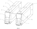
- a plurality of handle mechanisms arranged in parallel is rotatably assembled at the operating end of the housing; two adjacent handle mechanisms are connected in linkage; the end surface of the operating end on one side of at least one handle mechanisms is provided with one accommodating groove; each accommodating groove is covered by a respective cover plate; and the operating parts of the two adjacent cover plates are connected in linkage through the linkage shaft.
- the handle mechanism is rotatable to a closing position and an opening position; when the handle mechanism rotates to the closing position, the handle mechanism drives the circuit breaker to close through the operating mechanism; when the handle mechanism rotates to the opening position, the handle mechanism drives the circuit breaker to open through the operating mechanism; and the cover plate is provided with a limiting part; when the handle mechanism rotates to the closing position, the handle mechanism cooperates with the limiting part, such that the cover plate cannot rotate from the recovery position to the opening position; and when the cover plate rotates to the opening position, the handle mechanism is limited by the cover plate, such that the handle mechanism cannot rotate from the opening position to the closing position.
- the handle mechanism is provided with a first driving part; the handle mechanism can rotate to an unlocking position; the opening position is located between the closing position and the unlocking position; and when the handle mechanism rotates from the opening position to the unlocking position, the first driving part drives the locking mechanism to unlock.
- a side wall of the housing is provided with a limiting hole;
- the locking mechanism comprises an unlocking member, a locking member and an elastic member;
- the locking member is provided with a locking part;
- the elastic member drives the locking member, such that the locking part extends out of the limiting hole;
- the unlocking member is rotatably assembled between the locking member and the handle mechanism;
- the unlocking member is provided with a second unlocking part and a third driving part; and when the cover plate rotates to the opening position, the second driving part of the cover plate cooperates with the second unlocking part to drive the unlocking member to rotate; and
- the unlocking member drives the locking member through the third driving part, such that the locking part is retracted into the housing;
- the unlocking member is also provided with a first unlocking part; and when the handle mechanism rotates from the opening position to the unlocking position, the first driving part cooperates with the first unlocking part to drive the unlocking member to rotate, such that the third driving part cooperates with a cooperating part of the
- a side wall of the housing is provided with a limiting hole;
- the locking mechanism comprises an unlocking member and an elastic member;
- the unlocking member is rotatably assembled between the handle mechanism and the limiting hole;
- the unlocking member is provided with a second unlocking part and a locking part;
- the unlocking member is driven by the elastic member, such that the locking part extends out of the limiting hole; and when the cover plate rotates to the opening position, the second driving part of the cover plate cooperates with the second unlocking part to drive the unlocking member to rotate, such that the locking part is retracted into the housing;
- the unlocking member is also provided with a first unlocking part; and when the handle mechanism rotates from the opening position to the unlocking position, the first driving part cooperates with the first unlocking part to drive the unlocking member to rotate, such that the locking part is retracted into the housing.
- the unlocking member comprises a first rotating arm and a second rotating arm; the first rotating arm is connected to one end of the second rotating arm to form the rotating part, and the other end of the first rotating arm serving as the first unlocking part cooperates with the first driving part of the handle mechanism; and the other end of the second rotating arm as the third driving part abuts against the cooperating part of the locking member, or a boss serving as the locking part is arranged on the other end of the second rotating arm in a protruding manner.
- the present invention further provides a plug-in circuit breaker, comprising a housing, wherein the pulling and locking mechanism as above-mentioned is arranged at the operating end of the housing.
- the cover plate that is capable of being folded is provided.
- the cover plate is opened, and the second driving part of the cover plate unlocks the locking mechanism at the same time.
- the operating part may exert a pulling force or cooperate with a disassembling tool to extract the circuit breaker.
- the pulling and locking mechanism has the advantages of simple structure, high stability and convenience in extraction.
- the end surface of the operating end of the housing is provided with the accommodating groove, and when the cover plate rotates to the recovery position, the cover plate covers the accommodating groove and the operating part is accommodated in the accommodating groove, thereby achieving a compact structure and providing a sealing effect.
- One side of the cover plate away from the housing is a plane, and after the cover plate covers the accommodating groove, the cover plate maintains flush with the exterior of the housing, which is more conductive to integral formation of the cover plate and the housing.
- the linkage of two adjacent cover plates can realize integrated pulling, which is more convenient and reliable compared to the existing method that requires the individual pulling of each button piece.
- a side wall of the housing 1 is provided with a guide groove 17 (see FIG. 4 ).
- the guide groove 17 provides a guiding effect for the circuit breaker during plugging in.
- An opening of the guide groove 17 faces the wiring terminal 12.
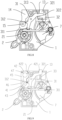
- An operating mechanism 7, a contact mechanism and a locking mechanism are arranged within the housing 1 between the operating end 11 and the wiring terminal 12.
- the contact mechanism includes a moving contact and a static contact that cooperate with each other, wherein the moving contact is connected to the operating mechanism 7, and the static contact is fixedly assembled within the housing 1.
- the handle mechanism 2 is in linkage with the operating mechanism 7 to drive the moving contact to contact or be away from the static contact.
- a side wall of the housing 1 between the operating end 11 and the wiring terminal 12 is provided with a limiting hole 13.
- the locking mechanism includes a locking part 321 that cooperates with the limiting hole 13. When the locking part 321 extends out of the limiting hole 13, the locking mechanism is in a locked state, and can be in limiting fit with the cabinet, such that the circuit breaker that is loaded into the cabinet cannot be drawn out.
- the locking mechanism 2 When the locking part 321 is retracted into the housing 1, the locking mechanism is in an unlocked state, and the circuit breaker that is loaded into the cabinet can be drawn out.
- the handle mechanism 2 can rotate to a closing position and an opening position. When the handle mechanism 2 rotates to the closing position, the handle mechanism 2 drives the circuit breaker to close through the operating mechanism 7; and when the handle mechanism 2 rotates to the opening position, the handle mechanism 2 drives the circuit breaker to open through the operating mechanism 7.
- a short-circuit protection mechanism, an arc extinguishing device, an overload protection mechanism and the like may also be arranged within the housing 1 between the wiring device and the contact mechanism, all of which fall within the prior art and will not be repeated here.
- a cover plate 4 is also rotatably connected to the operating end 11 of the housing 1; the cover plate 4 is provided with an operating part 42 and a second driving part 43; the cover plate 4 rotates between a recovery position and an opening position; when the cover plate 4 rotates to the recovery position, the operating part 42 is close to an end surface of the operating end 11; when the cover plate 4 rotates to the opening position, the second driving part 43 drives the locking mechanism to unlock, and the operating part 42 moves away from the end surface of the operating end 11 and is used for pulling the circuit breaker; and the cover plate 4 forms the pulling and unlocking mechanism of the circuit breaker.
- the plug-in circuit breaker can be extracted from the cabinet through the operating part 42, a force may be applied directly by the operating part 42, or a disassembling tool may also be assembled on the operating part 42, in order to apply a larger pulling force.
- the cover plate 4 and the locking mechanism form the pulling and locking mechanism of the circuit breaker. According to the pulling and locking mechanism and the plug-in circuit breaker applying the pulling and locking mechanism, the cover plate 4 that is capable of being folded is provided.
- the cover plate 4 is opened, and the second driving part 43 of the cover plate 4 unlocks the locking mechanism at the same time.
- the operating part 42 may exert a pulling force or cooperate with a disassembling tool to extract the circuit breaker.
- the pulling and locking mechanism has the advantages of simple structure, high stability and convenience in extraction.
- the cover plate 4 when the cover plate 4 rotates to the recovery position, the cover plate 4 is parallel to the end surface of the operating end 11 of the housing 1.
- the cover plate 4 When the cover plate 4 rotates to the opening position, the cover plate 4 forms an included angle with the end surface of the operating end 11.
- the included angle between the cover plate 4 and the end surface of the operating end 11 is 90°, that is, the cover plate 4 is perpendicular to the end surface of the operating end 11.
- the end surface of the operating end 11 of the housing 1 is provided with an accommodating groove 14, and the accommodating groove 14 is located on one side of the handle mechanism 2, and located on the upper side of the handle mechanism 2 in the drawings.
- the cover plate 4 rotates to the recovery position, the cover plate 4 covers the accommodating groove 14.
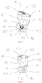
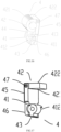
- a rotating part 41 and an operating part 42 are respectively arranged at both ends of the cover plate 4.
- the cover plate 4 is further provided with a second driving part 43 that may extend into the housing 1, and is rotatably connected to the housing 1 through the rotating part 41.
- the second driving part 43 may be arranged on one side of the rotating part 41 away from the operating part 42 in a protruding manner.
- the rotating part 41 and the operating part 42 are arranged on the same side of the cover plate 4 facing the end surface of the operating end 11 of the housing 1, and the other side of the cover plate 4 is a plane area 45.
- the cover plate 4 covers the accommodating groove 14, the rotating part 41 and the operating part 42 are accommodated in the accommodating groove 14.
- the plane area 45 remains flush with the exterior of the housing 1, that is, the plane area 45 remains flush with the end surface of the operating end 11.
- the cover plate 4 forms an integrated structure with the housing 1.
- the cover plate 4 plays the role of shielding the cover plate 4 and functions as a pulling member at the same time. Compared with pulling through button mechanisms, the pulling and locking mechanism has the advantages of simple structure, attractive appearance and convenience in extraction.
- the operating part 42 is a boss that is arranged on one side of the cover plate 4 in a protruding manner.
- the operating part 42 is provided with an operating surface 421 for applying a pulling force.
- the operating surface 421 intersects with one side of the cover plate 4 facing the housing 1, and is located on one side of the operating part 42 close to the rotating part 41.
- the cover plate 4 rotates to the opening position, the cover plate 4 is opposite to the end surface of the operating end 11 of the housing 1 and is used for applying a pulling force or cooperates with a disassembling tool to realize pulling.
- the boss of the operating part 421 may be an arc-shaped boss or an annular boss or a planar boss or other structure, and a concave surface of the arc-shaped boss, a hole wall of a center hole of the annular boss or a side wall of the planar boss is used as the operating surface 421.
- the operating surface 421 is an arc-shaped surface, which is convenient for fingers or the disassembling tool to apply.
- a plurality of anti-slip ridges is arranged on the surface of the operating part 42.
- a side wall of the operating part 42 away from the rotating part 41 is used as a pushing surface 422.
- the pushing surface 422 is provided with a plurality of anti-slip ridges, such that the cover plate 4 can be opened by operating the pushing surface 422.
- the rotating part 41 is rotatably connected to the housing 1 intermediately adjacent to the handle mechanism 2, wherein the second driving part 43 may be arranged on one side of the rotating part 41 away from the operating part 42.
- the second driving part 43 may be a boss or a rod-shaped structure.
- An opening that is communicated with the inside of the housing 1 is formed in one end of the accommodating groove 14, and the rotating part 41 is connected to the opening, such that the second driving part 43 may extend into the housing 1 and cooperate with the locking mechanism.
- the opening is formed in one side close to the handle mechanism 2, and when the cover plate 4 covers the accommodating groove 14, the operating part 42 is located at one end of the accommodating groove 14 away from the handle mechanism 2, and the rotating part 41 is located between the handle mechanism 2 and the operating part 42.
- the rotating part 41 may also be arranged on one side away from the handle mechanism 2; and when the cover plate 4 covers the accommodating groove 14, the operating part 42 is located between the rotating part 41 and the handle mechanism 2, such that the operation is relatively not very convenient.
- a limiting part 46 is arranged at one end of the cover plate 4 close to the handle mechanism 2.
- the handle mechanism 2 rotates to the closing position, the handle mechanism 2 cooperates with the limiting part 46, such that the cover plate 4 cannot rotate from the recovery position to the opening position, which prevents the cover plate 4 from being opened in a closed state during a pulling operation, thereby improving the safety of electricity utilization.
- the limiting part 46 is formed by a region of the plane area 45 close to one end of the handle mechanism 2.
- the handle mechanism 2 is limited by the cover plate 4, such that the handle mechanism 2 cannot rotate from the opening position to the closing position, so as to prevent a closing operation during pulling, thereby improving the safety of electricity utilization.
- a linkage hole 47 is formed in the operating part 42, and a linkage shaft 6 is assembled in the linkage hole 47.
- the circuit breaker is a multi-pole circuit breaker, and each circuit breaker pole is provided with one cover plate 4, two adjacent cover plates 4 are connected in linkage through the linkage shaft 6, which is conducive to pulling the multi-pole circuit breaker at the same time.
- the circuit breaker is the multi-pole circuit breaker, it is not necessary to provide the cover plate 4 and the locking mechanism for each circuit breaker pole, but at least one cover plate 4 is included.
- a circuit breaker pole corresponding to the cover plate 4 is provided with a locking mechanism.
- an intermediate circuit breaker pole may be provided with a cover plate 4 and a locking mechanism, or each pole may be provided with a cover plate 4 and a locking mechanism.
- the intermediate two circuit breaker poles are each provided with a cover plate 4 and a locking mechanism, or each pole may be provided with a cover plate 4 and a locking mechanism.
- a return spring 5 is further arranged between the cover plate 4 and the housing 1.
- the return spring 5 is rotatably assembled coaxially with the cover plate 4.
- Two elastic arms of the return spring 5 are respectively used in cooperation with the cover plate 4 and the housing 1 for providing a reset force for the cover plate 4.
- the cover plate 4 is driven to rotate to the recovery position, i.e., in a direction of covering the accommodating groove 14.
- the handle mechanism 2 may also be used for unlocking the locking mechanism, and the handle mechanism 2 can rotate to a closing position, an opening position and an unlocking position.
- the opening position is located between the closing position and the unlocking position.
- the handle mechanism 2 is provided with a first driving part 21. When the handle mechanism 2 rotates from the opening position to the unlocking position, the first driving part 21 drives the locking mechanism to unlock.
- the first embodiment of the plug-in circuit breaker is provided in conjunction with FIGs. 1-8 and 11-17 .
- a pulling and unlocking mechanism is cooperatively arranged at the operating end 11 of the housing 1.
- both ends of the housing 1 function as an operating end 11 and a wiring terminal 12 respectively.
- a side wall of the housing 1 connected between the operating end 11 and the wiring terminal 12 is provided with a limiting hole 13.
- the end surface of the operating end 11 is provided with a handle hole and an accommodating groove 14 respectively, wherein the handle hole is located in one side of the end surface of the operating end 11 away from the limiting hole 13, and the accommodating groove 14 is located on one side of the end surface of the operating end 11 close to the limiting hole 13.
- An inner side wall of the housing 1 below the handle hole is provided with a first connecting part 161.
- the handle mechanism 2 includes a handle body.
- the handle body includes a rotary connecting part and a handle part which are integrally formed.
- the rotary connecting part is in rotatable fit with the first connecting part 161.
- the handle part is connected to one side of the rotary connecting part and extends out of the housing 1 from the handle hole.
- a boss as the first driving part 21 is arranged on one side of the handle part in a protruding manner.
- the first driving part 21 and the handle part are respectively located on both sides of the rotary connecting part.
- An opening is formed in one end of the accommodating groove 14 close to the handle mechanism 2.
- the opening is communicated with the inside of the housing 1.
- An inner side wall of the housing 1 at the opening is provided with a connecting hole 15.
- a connecting shaft is assembled in the connecting hole 15, such that the cover plate 4 and the return spring 5 are coaxially assembled on the connecting shaft.
- the opening can be blocked; or, the opening is blocked by other structures on the inner wall of the housing 1, only for the second driving part 43 that may drive the locking mechanism to extend into the opening, such that foreign matters are prevented from entering into the housing 1.
- An end part of a bottom wall of the accommodating groove close to the opening is used for abutting against an elastic arm of the return spring 5.
- a bottom recess on one side of the accommodating groove 12 away from the opening forms an arc-shaped recess.
- the arc-shaped recess may correspond to the operating part 42 for accommodating the cover plate 4, such that when the cover plate 4 covers the accommodating groove 14, the cover plate 4 remains flush with the exterior of the housing 1, and one end of the accommodating groove 14 away from the handle mechanism 2 is open and sealed by the cover plate 4.
- the locking mechanism is correspondingly arranged below the accommodating groove 14.
- the locking mechanism includes a locking member 32, an unlocking member 31 and an elastic member 33, wherein the locking member 32 is arranged on one side of the limiting hole 13.
- the locking member 32 is preferably in limiting fit with the housing 1.
- the locking member 32 may also be rotatably connected to the housing 1.
- the locking member 32 is provided with a locking part 321 and a cooperating part 322.
- the locking member 32 is driven by the elastic member 33, such that the locking part 321 extends out of the limiting hole 13. At this moment, the locking mechanism is in a locked state.
- the unlocking member 31 is rotatably assembled between the handle mechanism 2 and the locking member 32.
- the unlocking member 31 is provided with a first unlocking part 311, a second unlocking part 312 and a third driving part 313.
- the second driving part 43 of the cover plate 4 cooperates with the second unlocking part 311 to drive the unlocking member 31 to rotate.
- the unlocking member 31 drives the locking member 32 through the third driving part 313, such that the locking part 321 is retracted into the housing 1.
- the locking mechanism is in an unlocked state at this time.
- the first driving part 21 cooperates with the first unlocking part 311 to drive the unlocking member 31 to rotate, such that the third driving part 313 presses the cooperating part 322 to drive the locking part to be retracted into the housing 1.
- a second connecting part 162 is arranged between the limiting hole 13 and the accommodating groove 14, and the second connecting part 162 corresponds to the lower side of the accommodating groove 14.
- the second connecting part 162 is located on the right side of the accommodating groove 14; the unlocking member 31 is rotatably connected to the housing 1 through the second connecting part 162; a slidable limiting part is arranged on at least one side of the limiting hole 13; and the locking member 32 is in sliding fit with the slidable limiting part, so that the locking member 32 performs linear motion on one side of the limiting hole 13 under the drive of the elastic member 33 and the unlocking member 31.
- the slidable limiting part may also not be arranged.
- the locking part 32 is rotatably assembled on one side of the limiting hole 13.
- the locking member 32 is driven by the elastic member 33 and the unlocking member 31 to rotate, so that the locking part 321 extends out of the limiting hole 13 or is retracted into the housing 1.
- a locking part 321 and a cooperating part 322 are arranged on one side of the locking member 32 facing the limiting hole 13, wherein the locking part 321 is a boss structure that is arranged in a protruding manner.
- the locking part 321 cooperates with the limiting hole 13.
- the cooperating part 322 is an inclined plane arranged on one side of the locking member 32.
- the cooperating part 322 may cooperate with the third driving part 313 of the unlocking member 31.
- the unlocking member 31 is correspondingly located below the accommodating groove 14, and a second unlocking part 312 is arranged on one side of the unlocking member 3 facing the accommodating groove 14.
- the second driving part 43 arranged on the cover plate 4 may extend into the housing 1.
- the second driving part 43 cooperates with the second unlocking part 312 to drive the unlocking member 31 and then drive the locking member 32, so that the locking part 321 is retracted into the housing 1.
- the unlocking member 31 may also be driven to unlock the locking member 32 as the handle mechanism 2 swings to the unlocking position.
- the unlocking member 31 includes a first rotating arm and a second rotating arm.
- the first rotating arm is connected to one end of the second rotating arm to form the rotating part 41.
- the rotating part 41 is in rotating fit with the second connecting part 162.
- the other end of the first rotating arm which functions as the first unlocking part 311, cooperates with the first driving part 21 of the handle mechanism 2.
- a boss is arranged in the middle part of the first rotating arm in a protruding manner. The boss is located on one side facing the cover plate 4 as the second unlocking part 312.
- the other end of the second rotating arm, which functions as the third driving part 313, abuts against the cooperating part 322 of the third driving part 313.
- the third driving part 313 is attached to the cooperating part 322 of the inclined plane. It should be noted that a position of the second unlocking part 312 is related to a position of the second driving part 43, but the position of the second unlocking part 312 is not limited to the middle part of the first rotating arm.
- the locking member 32 is block-shaped as a whole.
- a locking part 321 and a cooperating part 322 are arranged on one side of the locking member 32 facing the limiting hole 13.
- the locking part 321 is a boss that is arranged on one side of the locking member 32 in a protruding manner, such that one side of the locking member 32 facing the limiting hole 13 is integrally shaped as a Chinese character " ".
- An L-shaped groove is formed in the locking member 32 on the same side as the locking part 321.
- a side wall of the L-shaped groove facing the limiting hole 13 is an inclined plane which serves as the cooperating part 322 to abut against the unlocking member 31. As shown in FIGs.
- one side of the cooperating part 322 away from the unlocking member 31 is higher, one side of the cooperating part 322 close to the unlocking member 31 is lower, and the cooperating part 322 may preferably be attached to one side of the second rotating arm, so as to improve a cooperation degree of the cooperating part 322 and the second rotating arm.
- a boss structure is arranged on a body of the locking member 32 on one side away from the limiting hole 13 in a protruding manner, and a notch groove is formed in a corner of the boss structure. When a contact support rotates from a closing position to an opening position, the notch groove can avoid the contact support.
- one side of the notch groove When the contact support is located in the closing position, one side of the notch groove may abut against the contact support to limit the locking mechanism from unlocking.
- one side of the notch groove When the contact support is located in the opening position, and when the locking member 32 is in an unlocked state and retracted into the housing, one side of the notch groove may abut against the contact support to limit the contact support from closing.
- An assembling hole is formed in one side immediately adjacent to the boss structure.
- the elastic member 33 is cooperatively assembled between the assembling hole and an inner side wall of the housing 1. That is, both ends of the elastic member 33 abut against the third cooperating part 322 and the inner side wall of the housing 1 respectively, so that the elastic member 33 is deformed to drive the locking member 32 to slide in the housing 1.
- the operating mechanism 7 is rotatably assembled below the locking mechanism.
- the operating mechanism 7 includes a contact support that is rotatably connected to the housing 1.
- a jump buckle and a lock buckle are rotatably assembled on the contact support.
- the jump buckle is in buckling fit with one end of the lock latch.
- the contact support is connected in linkage with the handle mechanism 2 through a connecting rod.
- the moving contact is mounted on the contact support through a moving contact spring.
- the contact support is located on one side of the locking member 32.
- a convex limiting surface on the contact support rotates to a position corresponding to the locking member 32, and is in limiting fit with the locking member 32 through the contact support, in order to prevent the locking member 32 from moving and limit the locking part 321 from being retracted into the housing 1.
- a limiting surface of the contact support rotates to a position of avoiding the locking member 32.
- the cover plate 4 includes a cover plate body.
- the cover plate body has a width the same as the width of the end surface of the operating end 11.
- An operating part 42 and a rotating part 41 are arranged at both ends of the cover plate body respectively, wherein the operating part 42 and the rotating part 41 are arranged on the same side of the cover plate body in a protruding manner, and the other side of the cover plate body without the rotating part 41 and the operating part 42 is a plane area 45. After the accommodating groove 14 is closed, the plane area 45 remains flush with the exterior of the housing 1. As shown in FIGs.
- the rotating part 41 is a cylindrical boss that is arranged on one side of the cover plate body in a protruding manner.
- a shaft hole 413 is formed in the middle of the rotating part 41.
- a connecting shaft may be assembled in each of this shaft hole 413 and the connecting hole 15, such that the cover plate 4 is rotatably assembled in the housing 1.
- a mounting groove 411 is formed in an end surface of one end of the rotating part 41.
- a shaft hole 413 that penetrates through the rotating part 41 is formed in the bottom of the mounting groove 411.
- the return spring 5 is assembled in the mounting groove 411, and the return spring 5 is preferably a torsion spring that is sleeved onto the connecting shaft.
- a notch 412 is formed in one side of the mounting groove 411.
- One elastic arm of the return spring 5 extends out from the notch 412 and abuts against the housing 1, and the other elastic arm abuts against one side of the notch 412.
- a boss structure is arranged on one outer side of the rotating part 41 away from the operating part 42. The boss structure is used as a second driving part 43 for cooperating with the second unlocking part 312 of the unlocking part 31.
- the operating part 42 is an annular boss arranged on one side of the cover plate body.
- a wall of a center hole of the annular boss functions as an operating surface 421, and a central axis of the center hole is parallel to a central axis of the mounting groove 411.
- An outer diameter of the operating part 42 is greater than an outer diameter of the rotating part 41. That is, one side of the operating part 42 is more convex.
- the cover plate 4 covers the accommodating groove 14, one side of the operating part 42 may abut against the arc-shaped recess of the mounting groove 411. After the cover plate 4 is opened, the disassembling tool may be inserted into the center hole and attached to the operating surface 421.
- One side wall of the operating part 42 away from the rotating part 41 is used as a pushing surface 422.
- an arc-shaped outer side wall of one side of the operating part 42 away from the rotating part 41 is used as the pushing surface 422, and the pushing surface 422 is provided with a plurality of anti-slip ridges.
- the pushing surface 422 has the largest width, and one side of the annular boss close to the connecting part has a small width.
- a linkage hole 47 is formed in one end of the operating part 42 away from the rotating part 41, and the linkage shaft 6 may be assembled in the linkage hole 47, so that the two adjacent cover plate bodies may be connected in linkage.
- a reinforcing part 44 is connected between the operating part 42 and the rotating part 41 to improve the mechanical strength of the cover plate 4.
- the cover plate body on one side away from the rotating part 41, the operating part 42 and the reinforcing part 44 is used as the plane area 45.
- the cover plate 4 covers the accommodating groove 14.
- the plane area 45 remains flush with the exterior of the housing 1.
- One end of the plane area 45 as the limiting part 46 is in limiting fit with the handle mechanism 2, that is, the limiting part 46 is located at one end of the plane area 45 close to the handle mechanism 2.
- the rotating part 41 of the cover plate 4 is rotatably connected to the housing 1 on one side close to the handle mechanism 2, and the operating part 42 is located on one side away from the handle mechanism 2, but the connection mode of the cover plate 4 is not limited to this. That is, the rotating part 41 may be connected to the housing 1 on one side away from the handle mechanism 2.
- the operating part 42 is located on one side close to the handle mechanism 2, and the limiting part 46 and the operating part 42 are located at the same end of the cover plate body; or, the operating part 42 also serves as the limiting part 46.
- the handle mechanism 2 may also limit the cover plate 4 from being to be opened; and when the handle mechanism 2 swings to the opening position, the cover plate 4 may be opened.
- a second embodiment of the cover plate 4 is provided in conjunction with FIG. 15 .
- the cover plate 4 includes a cover plate body, which is identical with that in the first embodiment of the cover plate 4.
- a rotating part 41 and an operating part 42 are arranged at both ends on the same side of the cover plate body in a protruding manner, wherein the rotating part 41 is the same as that in the first embodiment of the cover plate 4.
- the cover plate body on one side away from the operating part 42 and the rotating part 42 is the plane area 45.
- the limiting part 46 is formed by one end of the plane area 45.
- the second embodiment is different from the first embodiment of the cover plate 4 in that a reinforcing part 44 is no longer arranged between the operating part 42 and the rotating part 41.
- the operating part 42 is an arc-shaped boss, a concave surface of the arc-shaped boss as the operating surface 421 faces the rotating part 41, and an arc-shaped outer side wall of the arc-shaped boss is used as the pushing surface 422, that is, a side away from the concave surface is used as the pushing surface 422 and is provided with anti-slip ridges.
- the operating part 42 is provided with a linkage hole 47 the same as that in the first embodiment.
- a third embodiment of the cover plate 4 is provided in conjunction with FIG. 16 .
- the cover plate 4 includes a cover plate body.
- a rotating part 41 and an operation part 42 are arranged at both ends on the same side of the cover plate body.
- a reinforcing part 44 is also arranged between rotating part 41 and the operation part 42.
- the operation part 42 is an annular boss of the same width. That is, the width of the operating part 42 at the pushing surface 422 is the same as the width of one side of the operating part 42 close to the rotating part 41. It may be understood that the width of the whole operating part 42 is approximately equal to the width of the end surface of the operating end 11, which is conducive to improving the mechanical strength of the operating part 42.
- the other structures of the cover plate 4 are the same as those of the first embodiment of the cover plate 4. That is, the rotating part 41, the mounting groove 411, the limiting part 46 and the plane area 45 are all the same as the structure of the first embodiment.
- a fourth embodiment of the cover plate 4 is provided in conjunction with FIG. 17 .
- the cover plate 4 includes a cover plate body.
- a rotating part 41 and an operating part 42 are arranged at both ends on the same side of the cover plate body, which is the same as the second embodiment.
- a reinforcing part 44 is not arranged between the rotating part 41 and the operating part 42.
- the operating part 42 in this embodiment is a plane boss of the same width.
- the plane boss may form a certain included angle with the cover plate body.
- a side wall of the plane boss that forms an included angle with the cover plate body is the operating surface 421.
- the plane boss and the cover plate body are perpendicular to each other, and one side wall of the plane boss perpendicular to the cover plate body is used as the operating surface 421.
- the end surface of the operating end 11 of the housing 1 may also not be provided with an accommodating groove 14.
- the cover plate 4 is rotatably or, detachably and rotatably connected to the housing 1.
- the cover plate 4 in the above embodiment is rotatably connected to the housing 1 on one side of the handle mechanism 2. That is, the rotating part 41 is rotatably connected to the housing 1 on one side of the handle mechanism 2, and the end surface of the operating end 11 is provided with a through hole for the second driving part 43 to extend into the housing 1.
- the operating part 42 is preferably arranged on one side of the cover plate 4 away from the end surface of the operating end 11 in a protruding manner.
- the cover plate 4 When the cover plate 4 rotates to the recovery position, the cover plate 4 may be attached to the end surface of the operating end 11 in parallel, so as to reduce a space occupied by the cover plate 4. If the operating part 42 is still arranged on one side of the cover plate 4 facing the end surface of the operating end 11 in a protruding manner, when the cover plate 4 is parallel to the end surface of the operating end 11, a certain distance is left between the cover plate 4 and the end surface of the operating end 11, or one end of the cover plate 4 away from the operating part 42 is attached to the end surface of the operating end 11. When the cover plate 4 is parallel to the end surface of the operating end 11, the operating part 42 is located outside the end surface of the operating end 11, in order to avoid the end surface of the operating end 11.
- the plug-in circuit breaker includes a housing 1 in which at least two parallel accommodating cavities are arranged.
- a circuit breaker pole is assembled in each accommodating cavity. That is, at least one partition plate is arranged in the housing 1, and the space in the housing 1 is divided into two accommodating cavities by the partition plate.
- each circuit breaker pole includes a circuit breaker pole housing. A space in each circuit breaker pole housing is used as an accommodating cavity.
- the housing 1 is formed by splicing a plurality of circuit breaker pole housings.
- Each circuit breaker pole includes the operating mechanism 7, the handle mechanism 2 and the locking mechanism as in the embodiment of the above-mentioned plug-in circuit breaker.
- the handle mechanisms 2 of the two adjacent circuit breaker poles are connected in linkage, so a plurality of parallel handle mechanisms 2 is rotatably assembled on the operating end 11 of the housing 1.
- the end surface of the operating end 11 on one side of at least one handle mechanisms 2 is provided with an accommodating groove 14.
- the accommodating groove 14 is correspondingly covered by one cover plate 4, and the operating parts 42 of the two adjacent cover plates 4 are connected in linkage through the linkage shaft 6.
- the end surface of the operating end 11 on one side of each handle mechanism 2 is provided with an accommodating groove 14, each accommodating groove 14 corresponds to one accommodating cavity, and each accommodating groove 14 is correspondingly covered by one cover plate 4 respectively.
- the operating part 42 is provided with a linkage hole 47 in which the linkage shaft 6 is assembled. Two adjacent cover plates 4 may be connected in linkage through the linkage shaft 6, and all cover plates 4 may be lift at the same time to pull the circuit breaker out of the cabinet.
- an inner side wall structure of each accommodating cavity is the same as the inner side wall of the housing 1 in the embodiment of the above plug-in circuit breaker, which is provided with a first connecting part 161 and a second connecting part 162, wherein the first connecting part 161 is correspondingly provided with a through hole for the handle linkage shafts 6 of the adjacent two handle mechanisms 2 to be connected in linkage.
- a side wall of the accommodating cavity is also provided with an avoiding hole. The connecting shafts of the two adjacent operating mechanisms 7 are connected in linkage through the avoiding holes.
- a side wall of the housing 1 is provided with at least two parallel limiting holes 13, wherein each limiting hole 13 corresponds to one accommodating cavity, and the locking part 321 in each circuit breaker pole correspondingly cooperates with the limiting hole 13.
- a third embodiment of the plug-in circuit breaker is provided in conjunction with FIG. 9 .
- the plug-in circuit breaker includes a housing 1, a handle mechanism 2 and an operating mechanism 7 that are identical with those in the first embodiment or the second embodiment, wherein the operating end 11 of the housing 1 may be provided with the same accommodating groove 14 as that in the first embodiment or the second embodiment, and the accommodating groove 14 is covered by the cover plate 4 in the above embodiments.
- the third embodiment is different from the above embodiments in that: the locking mechanism correspondingly arranged below the accommodating groove 14 includes an unlocking member 31 and an elastic member 33; the unlocking member 31 is rotatably assembled between handle mechanism 2 and the limiting hole 13; the unlocking member 31 is provided with a first unlocking part 311, a second unlocking part 312 and a locking part 321; the unlocking member 31 is driven by the elastic member 33, such that the locking part 321 extends out of the limiting hole 13; when the cover plate 4 rotates to the opening position, the second driving part 43 of the cover plate 4 cooperates with the second unlocking part 311 to drive the unlocking member 31 to rotate, such that the locking part 321 is retracted into the housing 1; and when the handle mechanism 2 rotates from the opening position to the unlocking position, the handle mechanism 2 drives the unlocking member 31 to rotate through the first unlocking part 311, such that the locking part 321 is retracted into the housing 1.
- the unlocking member 31 includes a first rotating arm and a second rotating arm, wherein the first rotating arm is connected to one end of the second rotating arm to form the rotating part 41, and the other end of the first rotating arm as the first unlocking part 311 cooperates with the first driving part 4 of the handle mechanism 2.
- a boss is arranged in the middle of the first rotating arm in a protruding manner.
- the boss as the second unlocking part 312 is located on one side facing the cover plate 4, and a boss as the locking part 321 is arranged on the other end of the second rotating arm in a protruding manner.
- the first unlocking part 311 and the second unlocking part 312 may be set as the same unlocking part and cooperate with the first driving part 21 and the second driving part 43 at the same time.
- the handle mechanism 2 and/or the cover plate 4 drive the locking part 32 through the unlocking member 31, such that the locking part 321 is retracted into the housing 1.
- the handle mechanism 2 and/or the cover plate 4 may also directly drive the locking member 32.
- the locking mechanism includes a locking member 32 and an elastic member 33, wherein the locking member 32 is arranged movably and is provided with a locking part 321, and the elastic member 33 drives the locking member 32 to move, such that the locking part 321 extends out of the limiting hole 13.
- the rotation of the handle mechanism 2 and/or the cover plate 4 exerts an acting force to the locking member 32, and the locking member 32 is stressed to move, such that the locking mechanism is unlocked when the locking part 321 is retracted into the housing 1.
- the handle mechanism 2 and/or the cover plate 4 may also drive the locking member 32 to unlock through a plurality of unlocking members.
- a fourth embodiment of the plug-in circuit breaker is provided in conjunction with FIG. 10 .
- the plug-in circuit breaker includes a housing 1, a handle mechanism 2 and an operating mechanism 7 that are identical with those of the first embodiment or the second embodiment, wherein the operating end 11 of the housing 1 may be provided with the same accommodating groove 14 as the first embodiment or the second embodiment, and the accommodating groove 14 is covered by the cover plate 4 in the above embodiments.
- the locking mechanism is correspondingly arranged below the accommodating groove 14.
- the locking mechanism includes an unlocking member 31, a locking member 32 and a return spring 33, wherein the locking member 32 and the return spring are the same as those in the first embodiment or the second embodiment.
- the structure of the unlocking member 31 is similar to that in the first embodiment or the second embodiment, but the unlocking member 31 is no longer provided with the second unlocking part 312. That is, the cover plate 4 in this embodiment cannot drive the locking mechanism to unlock.
- the cover plate 4 in this embodiment is only used for pulling and disassembling the circuit breaker.
- an accommodating groove 14 may also not be provided in this embodiment.
- a second unlocking part 312 in the locking mechanism is omitted; or the second driving part 43 is no longer arranged on the cover plate 4; or the second unlocking part 312 and the second driving part 43 are not arranged at the same time.
Landscapes
- Switch Cases, Indication, And Locking (AREA)
- Breakers (AREA)
Applications Claiming Priority (3)
| Application Number | Priority Date | Filing Date | Title |
|---|---|---|---|
| CN202210796265.1A CN117410141A (zh) | 2022-07-07 | 2022-07-07 | 断路器的拉拔锁定结构和插入式断路器 |
| CN202210796275.5A CN117410144A (zh) | 2022-07-07 | 2022-07-07 | 插入式断路器 |
| PCT/CN2023/106201 WO2024008170A1 (fr) | 2022-07-07 | 2023-07-06 | Structure de traction et de verrouillage de disjoncteur et disjoncteur enfichable |
Publications (2)
| Publication Number | Publication Date |
|---|---|
| EP4528779A1 true EP4528779A1 (fr) | 2025-03-26 |
| EP4528779A4 EP4528779A4 (fr) | 2026-04-29 |
Family
ID=89454444
Family Applications (1)
| Application Number | Title | Priority Date | Filing Date |
|---|---|---|---|
| EP23834936.9A Pending EP4528779A4 (fr) | 2022-07-07 | 2023-07-06 | Structure de traction et de verrouillage de disjoncteur et disjoncteur enfichable |
Country Status (5)
| Country | Link |
|---|---|
| EP (1) | EP4528779A4 (fr) |
| JP (1) | JP2025520250A (fr) |
| KR (1) | KR20250033140A (fr) |
| AU (1) | AU2023304563B2 (fr) |
| WO (1) | WO2024008170A1 (fr) |
Families Citing this family (1)
| Publication number | Priority date | Publication date | Assignee | Title |
|---|---|---|---|---|
| CN120767169B (zh) * | 2025-09-05 | 2025-11-14 | 浙江德菱科技股份有限公司 | 一种塑壳断路器 |
Family Cites Families (11)
| Publication number | Priority date | Publication date | Assignee | Title |
|---|---|---|---|---|
| CN205789579U (zh) * | 2016-06-08 | 2016-12-07 | 浙江正泰电器股份有限公司 | 断路器分、合闸按钮的锁定装置 |
| CN107833799B (zh) * | 2017-10-26 | 2024-09-20 | 上海良信电器股份有限公司 | 一种插入式断路器的固定及解锁机构 |
| CN110911240A (zh) * | 2019-12-18 | 2020-03-24 | 浙江明晖智能电气有限公司 | 一种插入式断路器的联锁装置 |
| CN212365873U (zh) * | 2020-07-29 | 2021-01-15 | 温州博士安全用品有限公司 | 一种小型断路器保护罩 |
| CN111883398B (zh) * | 2020-08-04 | 2024-06-18 | 德力西电气有限公司 | 一种插入式断路器的分合闸手柄机构和断路器 |
| CN213184161U (zh) * | 2020-10-31 | 2021-05-11 | 中韶电气股份有限公司 | 近方形断路器的安装锁定与拆装解锁机构 |
| CN214313098U (zh) * | 2020-12-18 | 2021-09-28 | 浙江正泰电器股份有限公司 | 多极断路器 |
| CN112750667A (zh) * | 2021-03-03 | 2021-05-04 | 北京明日电器设备有限责任公司 | 一种插入式断路器 |
| CN215527508U (zh) * | 2021-06-29 | 2022-01-14 | 上海良信电器股份有限公司 | 一种锁定机构及断路器 |
| CN114496672B (zh) * | 2022-02-25 | 2024-05-17 | 江西航同电气科技有限公司 | 一种插入式断路器锁定和解锁结构 |
| CN218385048U (zh) * | 2022-07-07 | 2023-01-24 | 上海诺雅克电气有限公司 | 断路器的拉拔锁定结构和插入式断路器 |
-
2023
- 2023-07-06 JP JP2024563156A patent/JP2025520250A/ja active Pending
- 2023-07-06 EP EP23834936.9A patent/EP4528779A4/fr active Pending
- 2023-07-06 WO PCT/CN2023/106201 patent/WO2024008170A1/fr not_active Ceased
- 2023-07-06 KR KR1020247035557A patent/KR20250033140A/ko active Pending
- 2023-07-06 AU AU2023304563A patent/AU2023304563B2/en active Active
Also Published As
| Publication number | Publication date |
|---|---|
| WO2024008170A1 (fr) | 2024-01-11 |
| AU2023304563B2 (en) | 2025-11-27 |
| EP4528779A4 (fr) | 2026-04-29 |
| AU2023304563A1 (en) | 2025-01-09 |
| KR20250033140A (ko) | 2025-03-07 |
| JP2025520250A (ja) | 2025-07-03 |
Similar Documents
| Publication | Publication Date | Title |
|---|---|---|
| CN109585233B (zh) | 小型断路器 | |
| EP4528779A1 (fr) | Structure de traction et de verrouillage de disjoncteur et disjoncteur enfichable | |
| EP4138109B1 (fr) | Disjoncteur enfichable | |
| CN215680571U (zh) | 一种隔离开关的触头系统 | |
| CN218385048U (zh) | 断路器的拉拔锁定结构和插入式断路器 | |
| CN115512998A (zh) | 双操作轴三工位操动装置 | |
| CN222414423U (zh) | 遥控钥匙 | |
| AU2020442183B2 (en) | Circuit breaker | |
| CN201546076U (zh) | 洗衣机门锁 | |
| CN212411974U (zh) | 连接件、锁定机构、固定机构、安装组件和断路器 | |
| CN211350531U (zh) | 插入式断路器 | |
| CN212411971U (zh) | 一种分合闸指示机构及断路器 | |
| CN223273172U (zh) | 一种隔离机构及开关装置 | |
| CN218676991U (zh) | 插入式断路器 | |
| CN218568744U (zh) | 用于拉拔的盖板 | |
| CN114695028A (zh) | 一种隔离开关 | |
| CN218385070U (zh) | 插入式断路器 | |
| CN217485378U (zh) | 指示装置和负荷断路开关 | |
| CN117954286B (zh) | 一种智能断路器 | |
| CN117410141A (zh) | 断路器的拉拔锁定结构和插入式断路器 | |
| CN217740415U (zh) | 隔离开关闭锁装置 | |
| CN218004747U (zh) | 插入式断路器 | |
| CN224096657U (zh) | 多极断路器的锁定结构和多极断路器 | |
| CN111834172B (zh) | 锁定机构、固定机构、安装组件和断路器 | |
| CN117410144A (zh) | 插入式断路器 |
Legal Events
| Date | Code | Title | Description |
|---|---|---|---|
| STAA | Information on the status of an ep patent application or granted ep patent |
Free format text: STATUS: THE INTERNATIONAL PUBLICATION HAS BEEN MADE |
|
| PUAI | Public reference made under article 153(3) epc to a published international application that has entered the european phase |
Free format text: ORIGINAL CODE: 0009012 |
|
| STAA | Information on the status of an ep patent application or granted ep patent |
Free format text: STATUS: REQUEST FOR EXAMINATION WAS MADE |
|
| 17P | Request for examination filed |
Effective date: 20241218 |
|
| AK | Designated contracting states |
Kind code of ref document: A1 Designated state(s): AL AT BE BG CH CY CZ DE DK EE ES FI FR GB GR HR HU IE IS IT LI LT LU LV MC ME MK MT NL NO PL PT RO RS SE SI SK SM TR |
|
| DAV | Request for validation of the european patent (deleted) | ||
| DAX | Request for extension of the european patent (deleted) | ||
| A4 | Supplementary search report drawn up and despatched |
Effective date: 20260327 |
|
| RIC1 | Information provided on ipc code assigned before grant |
Ipc: H01H 71/10 20060101AFI20260323BHEP Ipc: H01H 9/20 20060101ALI20260323BHEP Ipc: H01H 71/02 20060101ALI20260323BHEP Ipc: H01H 73/08 20060101ALI20260323BHEP Ipc: H01H 9/22 20060101ALI20260323BHEP Ipc: H01H 9/28 20060101ALN20260323BHEP |