EP4528780A1 - Schutzschalterbetriebsmechanismus und schutzschalter - Google Patents
Schutzschalterbetriebsmechanismus und schutzschalter Download PDFInfo
- Publication number
- EP4528780A1 EP4528780A1 EP23879042.2A EP23879042A EP4528780A1 EP 4528780 A1 EP4528780 A1 EP 4528780A1 EP 23879042 A EP23879042 A EP 23879042A EP 4528780 A1 EP4528780 A1 EP 4528780A1
- Authority
- EP
- European Patent Office
- Prior art keywords
- pole
- arc
- phase
- center
- operating mechanism
- Prior art date
- Legal status (The legal status is an assumption and is not a legal conclusion. Google has not performed a legal analysis and makes no representation as to the accuracy of the status listed.)
- Pending
Links
Images








Classifications
-
- H—ELECTRICITY
- H01—ELECTRIC ELEMENTS
- H01H—ELECTRIC SWITCHES; RELAYS; SELECTORS; EMERGENCY PROTECTIVE DEVICES
- H01H71/00—Details of the protective switches or relays covered by groups H01H73/00 - H01H83/00
- H01H71/10—Operating or release mechanisms
-
- H—ELECTRICITY
- H01—ELECTRIC ELEMENTS
- H01H—ELECTRIC SWITCHES; RELAYS; SELECTORS; EMERGENCY PROTECTIVE DEVICES
- H01H71/00—Details of the protective switches or relays covered by groups H01H73/00 - H01H83/00
- H01H71/10—Operating or release mechanisms
- H01H71/1009—Interconnected mechanisms
-
- H—ELECTRICITY
- H01—ELECTRIC ELEMENTS
- H01H—ELECTRIC SWITCHES; RELAYS; SELECTORS; EMERGENCY PROTECTIVE DEVICES
- H01H71/00—Details of the protective switches or relays covered by groups H01H73/00 - H01H83/00
- H01H71/002—Details of the protective switches or relays covered by groups H01H73/00 - H01H83/00 with provision for switching the neutral conductor
-
- H—ELECTRICITY
- H01—ELECTRIC ELEMENTS
- H01H—ELECTRIC SWITCHES; RELAYS; SELECTORS; EMERGENCY PROTECTIVE DEVICES
- H01H71/00—Details of the protective switches or relays covered by groups H01H73/00 - H01H83/00
- H01H71/02—Housings; Casings; Bases; Mountings
- H01H71/0207—Mounting or assembling the different parts of the circuit breaker
- H01H71/0221—Majority of parts mounted on central frame or wall
-
- H—ELECTRICITY
- H01—ELECTRIC ELEMENTS
- H01H—ELECTRIC SWITCHES; RELAYS; SELECTORS; EMERGENCY PROTECTIVE DEVICES
- H01H71/00—Details of the protective switches or relays covered by groups H01H73/00 - H01H83/00
- H01H71/10—Operating or release mechanisms
- H01H71/12—Automatic release mechanisms with or without manual release
- H01H71/40—Combined electrothermal and electromagnetic mechanisms
-
- H—ELECTRICITY
- H01—ELECTRIC ELEMENTS
- H01H—ELECTRIC SWITCHES; RELAYS; SELECTORS; EMERGENCY PROTECTIVE DEVICES
- H01H71/00—Details of the protective switches or relays covered by groups H01H73/00 - H01H83/00
- H01H71/10—Operating or release mechanisms
- H01H71/50—Manual reset mechanisms which may be also used for manual release
- H01H71/52—Manual reset mechanisms which may be also used for manual release actuated by lever
- H01H71/522—Manual reset mechanisms which may be also used for manual release actuated by lever comprising a cradle-mechanism
- H01H71/525—Manual reset mechanisms which may be also used for manual release actuated by lever comprising a cradle-mechanism comprising a toggle between cradle and contact arm and mechanism spring acting between handle and toggle knee
-
- H—ELECTRICITY
- H01—ELECTRIC ELEMENTS
- H01H—ELECTRIC SWITCHES; RELAYS; SELECTORS; EMERGENCY PROTECTIVE DEVICES
- H01H1/00—Contacts
Definitions
- the present invention relates to the field of low-voltage electrical appliances, and more particularly to an operating mechanism of a circuit breaker and a circuit breaker including the operating mechanism of the circuit breaker.
- An objective of the present invention is to overcome the defects of the prior art and provide an operating mechanism of a circuit breaker, which allows a phase-pole shaft mechanism and an N-pole rotating shaft mechanism to rotate around different rotation centers.
- An operating mechanism of a circuit breaker comprising a support, and a rocker arm assembly and a jump buckle, a lock buckle in buckling fit with the jump buckle, a re-buckle in limiting fit with the lock buckle which are rotatably arranged on the support respectively, a first crank, an energy storage spring, a slide rail fixedly arranged relative to the support, a slider arranged on the slide rail and sliding back and forth along its extension direction, and a first link; wherein one end of the first crank is rotatably arranged on the jump buckle around an eighth center, and another end of the first crank is rotatably connected to one end of the first link and one end of the energy storage spring around an eighteenth center; another end of the first link is rotatably connected to the slider, and another end of the energy storage spring is rotatably connected to the rocker arm assembly; and the operating mechanism further comprises a phase-pole rotating shaft, an N-pole rotating shaft rotatably arranged around a twenty-second center, a second link,
- the rocker arm assembly and the second crank are respectively located at both ends of the operating mechanism, the phase-pole rotating shaft and the N-pole rotating shaft are arranged side by side, the third crank and the phase-pole rotating shaft are arranged close to the rocker arm assembly, and the N-pole rotating shaft is arranged close to the second crank; and in a horizontal direction of the operating mechanism, the rocker arm assembly and the third crank are arranged side by side, and the third crank, the phase-pole rotating shaft and the N-pole rotating shaft are located on the same side of the operating mechanism.
- the rocker arm assembly is rotatably arranged on the support around a fourth center, and the fourth center, the seventh center, the twenty-second center and the sixth center are sequentially positioned at four vertices of a quadrilateral;
- the second crank and the third crank are rotatably arranged on the support around the sixth center and seventh center respectively.
- the support is provided with a third crank guide hole
- the third link is rotatably connected with the third crank through the twentieth shaft
- the twentieth shaft is inserted into the third crank guide hole
- a shape of the third crank guide hole is matched with a moving trajectory of the twentieth shaft.
- the second crank, the third crank, the N-pole rotating shaft and the phase-pole rotating shaft are arranged to rotate synchronously in the same direction.
- the second crank is of a triangular-shaped plate structure, wherein a first apex angle is rotatably arranged around the sixth center, a second apex angle is rotatably connected to the second link and the third link around the nineteenth center respectively, and a third apex angle is rotatably connected to the fourth link around the twenty-first center.
- the third crank is of a triangular-shaped plate structure, wherein a first apex angle is rotatably arranged around the seventh center, a second apex angle is rotatably connected to the third link around the twentieth center, and a third apex angle is rotatably connected to the phase-pole rotating shaft around a twenty-fourth center.
- the support comprises two support side plates that are oppositely arranged; each support side plate comprises a first side plate portion and a second side plate portion which are connected to each other; in a horizontal direction of the operating mechanism, the first side plate portion and the second side plate portion are arranged side by side; the rocker arm assembly, the jump buckle, the lock buckle, the re-buckle and the second crank are rotatably arranged on the first side plate portion respectively; a V-shaped groove and a slide rail are respectively arranged at both ends of the first side plate portion in a vertical direction of the operating mechanism; the rocker arm assembly is arranged to swing in the V-shaped groove; and the third crank is rotatably arranged on the second side plate portion.
- the operating mechanism comprises two sets of second cranks which are symmetrically arranged, two sets of third links which are symmetrically arranged, two sets of third cranks which are symmetrically arranged, two sets of fourth links which are symmetrically arranged, two sets of sliders which are symmetrically arranged, two sets of first links which are symmetrically arranged, two sets of first cranks which are symmetrically arranged, two sets of energy storage springs which are symmetrically arranged, and two sets of slide rails which are symmetrically arranged on the two support side plates;
- the rocker arm assembly comprises a handle and a rocker arm which are connected fixedly;
- the rocker arm comprises two rocker arm legs which are arranged oppositely, and the two rocker arm legs are rotatably arranged in the V-shaped grooves of the two support side plates through a fourth shaft respectively;
- the two sets of first cranks are respectively arranged on both sides of the jump buckle, and one ends of the two sets of first cranks are rotatably connected to the jump buckle through an
- the slider when the operating mechanism is in an opened state or a tripped state, the slider is in limiting fit with the slide rail to prevent the slider from sliding, and the slider blocks the first crank from rotating through the first link.
- each slide rail is of a groove-like structure or a hole-like structure.
- the slide rail is arranged on the support.
- the operating mechanism further comprising a first draw bar and a transmission jump buckle that are in buckling fit with each other and rotatably arranged respectively, wherein when a short-circuit and/or overload fault occurs in a circuit where the circuit breaker is located, the first draw bar is driven by an external structure to rotate and releases buckling fit from the transmission jump buckle, and the transmission jump buckle rotates to drive the operating mechanism to trip.
- the operating mechanism further comprising a thermomagnetic tripping mechanism, wherein the thermomagnetic tripping mechanism serves as an external structure of the first draw bar; and when a short-circuit and an overload fault occurs in the circuit where the phase-pole breaking unit is located, the first draw bar is driven to rotate and releases buckling fit from the transmission jump buckle.
- a thermomagnetic tripping mechanism serves as an external structure of the first draw bar
- the rocker arm assembly drives the transmission jump buckle to reset and restore buckling fit with the first draw bar.
- the first draw bar is rotatably arranged on the support around the fifth center
- the transmission jump buckle is rotatably arranged on the support around the seventh center
- the first draw bar and the transmission jump buckle are both located between the two support side plates of the support.
- the operating mechanism of the circuit breaker in the present invention implements respective driving of the N-pole rotating shaft and the phase-pole rotating shaft by arranging two sets of four-link structures, and allows rotation centers of the N-pole rotating shaft and the phase-pole rotating shaft to be different, providing higher flexibility for the design of the operating mechanism and the layout of the circuit breaker.
- the slider converts a movement position of the first link in the opening and closing processes of the operating mechanism into a displacement of the slider, which is conducive to the actual measurement and the adjustment of parameters such as a size of a structure connected to the slider.
- the rotation of the mechanism links and the transfer of a torque can be implemented by the first crank, the first link and the slider, and the operating mechanism can implement the opening, closing and tripping operations without the connection to the phase-pole rotating shaft and/or N-pole rotating shaft, which is convenient for the modular production of the operating mechanism.
- the slide rail provides a guiding function for the slider, and also serve as a supporting point to provide a supporting force for the first link and the slider, so that the operating mechanism may have the stable closing position, opening position and tripping position without the connection to the rotating shaft mechanism of the breaking unit, making the operating mechanism become an independently operable component, which is conducive to the modular assembly and production of the operating mechanism. and provides more design space for the distribution of the operating mechanism in the circuit breaker.
- the operating mechanism does not need to cooperate with a rotating shaft mechanism of the breaking unit, which avoids the loss of the contact system of the breaking unit during the test process and reduces R&D and production costs.
- circuit breaker of the present invention The specific implementation of a circuit breaker of the present invention will be further described below with reference to the embodiments given in FIGs. 1 to 17b .
- the circuit breaker of the present invention is not limited to the description of the following embodiments.
- the circuit breaker of the present invention includes an operating mechanism 100 and at least one set of breaking unit, wherein the at least one set of breaking unit is a phase-pole breaking unit, and the operating mechanism 100 is in driving connection with the breaking unit to drive the driving unit to be closed or broken, so that the circuit breaker is closed and opened.
- the circuit breaker of the present invention is preferably a multi-phase circuit breaker, e.g., a two-phase (2P or P+N), three-phase (2P+N) or four-phase (3P+N) circuit breaker.
- the circuit breaker of the present invention further includes a circuit breaker outer housing for accommodating and mounting the operating mechanism 100 and the breaking units
- the circuit breaker outer housing includes a outer-housing main body (not shown), a face cover 103 and a base 104
- the base 104 is arranged in a space formed by the outer-housing main body and the face cover 103 that are oppositely buckled together
- the operating mechanism 100 and the breaking units are respectively arranged in corresponding spaces of the base 104.
- the base 104 is provided with a plurality of installation spaces arranged side by side, wherein each installation space accommodates one breaking unit.
- each phase-pole breaking unit includes a phase-pole housing.
- the phase-pole housing includes a first phase-pole half-housing 106 and a second phase-pole half-housing 107 which are oppositely buckled, wherein the first phase-pole half-housing 106 and the second phase-pole half-housing 107 are oppositely buckled to form a phase-pole installation space which is used for accommodating a phase-pole contact system 93 and a phase-pole arc-extinguishing system 94.
- phase-pole housing is of a convex structure as a whole, a phase-pole rotating shaft structure of the phase-pole contact system 93 is arranged at the upper part of the convex structure, and the phase-pole arc-extinguishing system 94 is arranged at the lower part of the convex structure.
- phase-pole housing is also provided with a tripping mechanism mounting cavity that is used for accommodating a thermomagnetic tripping mechanism 105 (described later).
- the phase-pole installation space and the tripping mechanism mounting cavity are arranged independently of each other.
- a partition wall is preferably arranged between the tripping mechanism mounting cavity and the phase-pole installation space.
- the partition wall is provided with an avoidance opening for a conductor plate 67 of the thermomagnetic tripping mechanism 105 to be connected with a phase-pole conductor 40 of the phase-pole rotating shaft mechanism.
- the tripping mechanism mounting cavity is located on one side of the phase-pole rotating shaft mechanism in a horizontal direction of the operating mechanism 100.
- the circuit breaker in the present embodiment is preferably a 2P+N-type three-phase circuit breaker, which includes three sets of breaking units.
- the three sets of breaking units are preferably arranged side by side along the thickness direction of the operating mechanism 100 (that is, a side-by-side direction of two support side plates of a support 1 of the operating mechanism 100), wherein one set of breaking unit is a N-pole breaking unit 102 for breaking and closing an N-pole circuit circuit, and the other two sets of breaking units are phase-pole breaking units 101 for breaking and closing corresponding phase-pole circuits.
- the two sets of phase-pole breaking units 101 are preferably distributed on both sides of the N-pole breaking units 102 and are located on both sides of the two support side plates of the support 1 of the operating mechanism 100 respectively.
- the operating mechanism 100 is connected to the phase-pole housings through a first phase-pole positioning shaft 77 and a second phase-pole positioning shaft 78 which are arranged side by side at intervals.
- the first phase-pole positioning shaft 77 and the second phase-pole positioning shaft 78 preferably pass through the support side plates of the support 1 of the operating mechanism 100 and the phase-pole housings.
- Parts of the first phase-pole positioning shaft 77 and the second phase-pole positioning shaft 78, which are inserted into the phase-pole housings, are preferably sleeved with a first phase-pole insulating sleeve 81 and the second phase-pole insulating sleeve 82 respectively, so as to prevent different phase-pole breaking units from interphase breakdown through the first phase-pole positioning shaft 77 and the second phase-pole positioning shaft 78 under a high voltage.
- the operating mechanism 100 is connected to a N-pole housing through a first N-pole positioning shaft 79 and a second N-pole positioning shaft 80 which are arranged side by side at intervals.
- the first N-pole positioning shaft 79 and the second N-pole positioning shaft 80 preferably pass through the support side plates of the support 1 of the operating mechanism 100 and the N-pole housing.
- each phase-pole breaking unit 102 includes a phase-pole contact system 93.
- the phase-pole contact system 93 includes a phase-pole rotating shaft mechanism and a phase-pole static contact 111 that are cooperatively used.
- the phase-pole rotating shaft mechanism is rotatably arranged in the phase-pole housing around a seventh center 7S.
- the phase-pole rotating shaft mechanism includes a phase-pole rotating shaft 39 that is rotatably arranged and a phase-pole moving contact 41 that is arranged on the phase-pole rotating shaft 39 and cooperates with the phase-pole static contact 111.
- each phase-pole breaking unit 102 further includes a phase-pole arc-extinguishing system 94 that cooperates with the phase-pole contact system.
- the phase-pole rotating shaft mechanism and the operating mechanism 100 are arranged side by side.
- the phase-pole rotating shaft mechanism and the phase-pole arc-extinguishing system 94 are arranged side by side.
- the above-mentioned layout makes a trajectory of the phase-pole moving contact 41 breaking from the phase-pole static contact 111 be directly opposite to a bottom surface of a housing of the phase-pole breaking unit 102, which is conducive to a horizontal design of the phase-pole arc-extinguishing system 94, provides a larger design space for the phase-pole arc-extinguishing system, is conducive to improving a heat capacity of the phase-pole arc-extinguishing system 94, and improves a breaking voltage upper limit of the phase-pole arc-extinguishing system 94.
- the horizontal direction of the operating mechanism 100 is a left-right direction
- the vertical direction of the operating mechanism 100 is an up-down direction.
- the phase-pole rotating shaft mechanism includes a phase-pole rotating shaft 39, a phase-pole moving contact 41, a phase-pole contact spring 44 and a phase-pole conductor 40.
- a phase-pole rotating shaft mounting cavity is formed in the middle of the phase-pole rotating shaft 39.
- the phase-pole moving contact 41 includes a phase-pole moving contact connecting end and a phase-pole moving conductor rod, wherein one end of the phase-pole moving conductor rod is connected to the phase-pole moving contact connecting end, and the other end of the phase-pole conductor rod is provided with a phase-pole moving contact point.
- the phase-pole moving contact connecting end is rotatably arranged in the phase-pole rotating shaft mounting cavity around a fifteenth center 15S.
- the fifteenth center 15S coincides with a seventh center 7S.
- the phase-pole conductor 40 includes a conductor connecting portion of a U structure.
- the conductor connecting portion includes a connecting portion bottom plate and a pair of connecting portion connecting arms. A free end of each connecting portion connecting arm is rotatably connected to the phase-pole moving contact connecting end.
- the two connecting portion connecting arms are also connected via a conductor connecting shaft 64, such that the two connecting portion connecting arms press against the phase-pole moving contact connecting end.
- the conductor connecting shaft 64 is located between the connecting portion bottom plate and a free end of the connecting portion connecting arm.
- phase-pole rotating shaft 39, the connecting portion connecting arm and the phase-pole moving contact connecting end are connected via the phase-pole connecting shaft 48.
- the phase-pole contact spring 44 is arranged in the phase-pole rotating shaft mounting cavity, wherein one end of the phase-pole contact spring 44 is connected to the phase-pole moving contact 41 through a first phase-pole contact spring shaft 45, and the other end of the phase-pole contact spring 44 is rotatably arranged on the phase-pole rotating shaft 39 around a thirteenth center 13S.
- the fifteenth center 15S is located on one side of an axis of the phase-pole contact spring 44, and the phase-pole contact spring 44 exerts an acting force to the phase-pole moving contact 41, such that the phase-pole moving contact 41 is in limiting fit with the phase-pole rotating shaft 39 to keep relatively stationary. As shown in FIGs. 7a-8b , when the phase-pole rotating shaft mechanism rotates around the seventh center 7S to drive the phase-pole moving contact 41 and the corresponding phase-pole static contact 111 to be closed or broken, the fifteenth center 15S is located on one side of an axis of the phase-pole contact spring 44, and the phase-pole contact spring 44 exerts an acting force to the phase-pole moving contact 41, such that the phase-pole moving contact 41 is in limiting fit with the phase-pole rotating shaft 39 to keep relatively stationary. As shown in FIGs.
- phase-pole moving contact 41 when the phase-pole moving contact 41 is repelled by an electric repulsion force between the phase-pole moving contact 41 and the phase-pole static contact 111, and the phase-pole moving contact 41 drives the phase-pole contact spring 44 to rotate over a dead center, so that the fifteenth center 15S is located on the other side of the axis of the phase-pole contact spring 44; and the phase-pole contact spring 44 exerts an acting force to the phase-pole moving contact 41 to lock the phase-pole moving contact 41 at a disconnecting position, so as to avoid the phase-pole moving contact 41 from falling back to be closed with the phase-pole static contact 111 again so as to result in secondary short-circuiting.
- the phase-pole rotating shaft mechanism further includes an insulator 42.
- the insulator 42 includes an insulator mounting cavity for accommodating the phase-pole moving conductor rod of the phase-pole moving contact 41, and an insulator arc barrier.
- the insulator arc barrier cooperates relatively with a circumferential side wall of the phase-pole rotating shaft 39.
- phase-pole moving contact 41 rotates relative to the phase-pole rotating shaft 39 (e.g., when the phase-pole moving contact 41 is repelled by an electric repulsion force)
- a gap between the phase-pole moving contact 41 and the phase-pole rotating shaft 39 is blocked, so as to avoid electric arc particles from entering the phase-pole rotating shaft mounting cavity, prevent the phase-pole rotating shaft 39 from being stuck inside, and isolate the phase-pole rotating shaft mounting cavity from the corresponding phase-pole arc-extinguishing system 94, which is conducive to an electric arc gas entering the arc-extinguishing system 94.
- the N-pole breaking unit 101 further includes an N-pole arc-extinguishing system 940 that is used in conjunction with the N-pole contact system; and in a horizontal direction of the operating mechanism 100, the N-pole contact system and the N-pole arc-extinguishing system 940 are arranged side by side.
- the N-pole rotating shaft mechanism is the same as the phase-pole rotating shaft mechanism, which will not be described here.
- the operating mechanism has three working states, namely an opened state, a closed state and a tripped state (opened-tripped state), and the operating mechanism in the tripped state can be switched to the opened state by re-buckling.
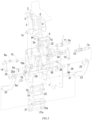
- the operating mechanism 100 includes a support 1, and a rocker arm assembly, a jump buckle 7, a lock buckle 10 in buckling fit with the jump buckle 7 and a re-buckle 9 in limiting fit with the lock buckle 10 which are rotatably arranged on the support 1 respectively, and a first crank 14, an energy storage spring 4, a slide rail 1-0 fixed relative to the support 1, a slider 18, a first link 16, a second link 19, a second crank 21 rotatably arranged around a sixth center 6S, a third link 23, a third crank 15, and a fourth link 29.
- the rocker arm assembly has three working positions, which are a closing position, a tripping position and an opening position, which are distributed sequentially and correspond to the closed state, the tripped state and the opened state of the operating mechanism 100 respectively.
- the energy storage spring 4 first stores energy and then releases energy to drive the operating mechanism to be quickly switched between the closed state and the opened state.
- the first crank 14 is rotatably arranged on the jump buckle 7S around an eighth center 8S, the other end of the first crank 14 is rotatably connected to one end of the first link 16 and one end of the energy storage spring 4 around an eighteenth center 18S, the other end of the first link 16 is connected to the slider 18, and the other end of the energy storage spring 4 is rotatably connected to the rocker arm assembly.
- the phase-pole rotating shaft 39 and the third crank 25 are rotatably arranged around the seventh center 7S respectively, and the N-pole rotating shaft 30 is rotatably arranged around a twenty-second center 22S.
- the rocker arm assembly includes a re-buckling structure 6 that is used for driving the jump buckle 7 to be re-buckled with the lock buckle 10.
- the rocker arm assembly swings to the opening position to drive the jump buckle 7 through the re-buckling structure 6, such that the jump buckle 7 restores the buckling fit with the lock buckle 10.
- the first crank 14 includes a crank limiting structure 15 that is in limiting fit with the jump buckle 7.
- the crank limiting portion 15 is in limiting fit with the jump buckle 7.
- the operating mechanism implements respective driving of the N-pole rotating shaft 30 and the phase-pole rotating shaft 39 by arranging two sets of four-link structures, and allows rotation centers of the N-pole rotating shaft 30 and the phase-pole rotating shaft 39 to be different, providing higher flexibility for the design of the operating mechanism and the layout of the circuit breaker.
- the rocker arm assembly and the second crank 21 are respectively located at two ends of the operating mechanism 100, the phase-pole rotating shaft 39 and the N-pole rotating shaft 30 are arranged side by side, the third crank 25 is arranged close to the rocker arm assembly, and the N-pole rotating shaft 30 is arranged close to the second crank 21.
- the rocker arm assembly and the third crank 25 are located on one side of the operating mechanism 100 in the horizontal direction, and the second crank 21 and the N-pole rotating shaft 30 are located on the other side of the operating mechanism 100 in the horizontal direction; and in the horizontal direction of the operating mechanism 100, the rocker arm assembly and the third crank 25 are arranged side by side, and the third crank 25, the phase-pole rotating shaft 39 and the N-pole rotating shaft 30 are located on the same side of the operating mechanism 100. Specifically, in a direction as shown in FIGs.
- the rocker arm assembly and the second crank 21 are respectively located at upper and lower ends of the operating mechanism 100, the phase-pole rotating shaft 39 and the N-pole rotating shaft are arranged side by side at intervals in a vertical direction, the rocker arm assembly and the third crank 25 are located on the upper side, and the second crank 21 and the N-pole rotating shaft 30 are located on the lower side; and the third crank 25, the phase-pole rotating shaft 39 and the N-pole rotating shaft 30 are all located on the right side of the operating mechanism 100.
- the phase-pole rotating shaft 39 and the operating mechanism 100 are arranged side by side, such that a length size of the circuit breaker is fully utilized, more space is reserved for the design of the phase-pole arc-extinguishing system 94, and the horizontal design of the phase-pole arc-extinguishing system 94 can be realized.
- the second crank 21, the third crank 25, the N-pole rotating shaft 30 and the phase-pole rotating shaft 39 are arranged to ratate synchronously in the same direction. That is, the second crank 21, the third crank 25, the N-pole rotating shaft 30 and the phase-pole rotating shaft 39 maintain synchronous rotation in the same rotation direction simultaneously.
- the second crank 21, the third crank 25, the N-pole rotating shaft 30 and the phase-pole rotating shaft 39 rotate clockwise at the same time in the closing process of the operating mechanism, and rotate counterclockwise at the same time in the opening process of the operating mechanism.
- the fourth link 29 is rotatably connected to the second crank 21 around a twenty-first center 21S, and the other end of the fourth link 29 is rotatably connected to the N-pole rotating shaft 30 around a twenty-third center 23S.
- the jump buckle 7 is rotatably arranged on the support 1 through a first shaft 1a whose axis coincides with a first center 1S.
- the rocker arm assembly is rotatably arranged on the support 1 through a fourth shaft 4a whose axis coincides with a fourth center 4S.
- the lock buckle 10 is rotatably arranged on the support 1 through a second shaft 2a whose axis coincides with a second center 2S.
- the re-buckle 9 is rotatably arranged on the support 1 through a third shaft 3a whose axis coincides with a third center 3S.
- the first crank 14 is rotatably connected to the jump buckle 7 through an eighth shaft 8a whose axis coincides with an eighth center 8S.
- the first crank 14, the first link 16 and the energy storage spring 4 are rotatably connected to an eighteenth shaft 18a whose axis coincides with an eighteenth center 18S.
- the second crank 21 is rotatably arranged on the support 1 through a sixth shaft 6a whose axis coincides with a sixth center 6S.
- the third crank 25 is rotatably arranged on the support 1 through a seventh shaft 7a whose axis coincides with the seventh center 7S.
- the second link 19, the third link 23 and the second crank 21 are rotatably connected to a nineteenth shaft 19a whose axis coincides with the nineteenth center 19S.
- the second link 19 is also rotatably connected to the third crank 25a through a twentieth shaft 20a whose axis coincides with the twentieth center 20S.
- the second crank 21 is rotatably connected to the fourth link 29 through a twenty-first shaft 21a whose axis coincides with the twenty-first center 21S.
- the third crank 25 is in driving connection with the phase-pole rotating shaft 39 through a phase-pole driving shaft 28, and an axis of the phase-pole driving shaft 28 is arranged parallel to a rotation axis of the third crank 25; and the phase-pole housing is preferably provided with a phase-pole housing avoidance hole that is used for avoiding the phase-pole driving shaft 28, a shape of the phase-pole housing avoidance hole is matched with a moving trajectory of the phase-pole driving shaft 28, and the phase-pole housing avoidance hole is preferably a sector-shaped hole.
- phase-pole driving shaft 28 is in limiting fit with the support 1, which prevents the phase-pole rotating shaft 39 from further rotating, such that the phase-pole rotating shaft mechanism and the phase-pole moving contact 41 are limited in the breaking position.
- the support 1 is provided with a third crank guide hole
- the twentieth shaft 20a is inserted into the third crank guide hole
- a shape of the third crank guide hole is matched with a moving trajectory of the twentieth shaft 20a.
- the third crank guide hole is a sector-shaped hole.
- the operating mechanism 100 further includes a lock buckle spring 11.
- the lock buckle spring 11 is a torsion spring sleeving on the second shaft 2a, and two ends of the torsion spring are matched with the lock buckle 10 and the re-buckle 9 respectively.
- the nineteenth shaft 19a when the operating mechanism 100 is in the opened state or the tripped state, the nineteenth shaft 19a is in limiting fit with the support 1, preventing the second crank 21 from further rotating. Further, the nineteenth shaft 19a abuts against side edges of the support side plates of the support 1 in order to achieve limiting fit.
- the fourth center 4S, the seventh center 7S, the twenty-second center 22S and the sixth center 6S are sequentially located at four vertices of a quadrilateral. Further, the fourth center 4S, the seventh center 7S, the twenty-second center 22S and the sixth center 6S are sequentially located at four vertices of a quadrilateral in a clockwise direction and are arranged parallel to one another at intervals. Furthermore, the seventh center 7S, the twenty-second center 22S and the sixth center 6S are sequentially located at three vertices of a triangle in a clockwise direction, and the triangle is preferably an acute triangle.
- the sixth center 6S, the seventh center 7S, the twentieth center 20S and the nineteenth center 19S are sequentially located at four vertices of a quadrilateral. Further, the sixth center 6S, the seventh center 7S, the twentieth center 20S and the nineteenth center 19S are sequentially located at four vertices of a quadrilateral in a clockwise direction. That is, the second crank 21, the third link 23 and the third crank 25 form a set of four-link structure which is the first four-link structure 97.
- the six center 6S, the twenty-second center 22S, the twenty-third center 23S and the twenty-first center 21S are sequentially located at four vertices of a quadrilateral. Further, the sixth center 6S, the twenty-second center 22S, the twenty-third center 23S and the twenty-first center 21S are sequentially located at four vertices of a quadrilateral in a clockwise direction. That is, the second crank 21, the fourth link 29 and the N-pole rotating shaft 30 form a set of four-link structure which is the second four-link structures 98.
- the operating mechanism in the present embodiment by arranging two sets of four-link structures, namely, the first four-link structure 97 and the second four-link structure 98, the action design requirements of operating mechanism and rotating shaft system of 2P and 2P+N-type circuit breakers are met, and a design scheme in which rotating shafts of multiple poles are of different axes (e.g., the phase pole rotating shaft 39 and the N-pole rotating shaft 30 are of different axes) is achieved.
- the second crank 21 is of a triangular plate structure, wherein a first apex angle is rotatably arranged around the sixth center 6S, a second apex angle is rotatably connected to the second link 19 and the third link 23 around the nineteenth center 19S respectively, and a third apex angle is rotatably connected to the fourth link 29 around the twenty-first center 21S.
- the structure of the second crank 21 is not limited to the triangular plate structure, as long as the positions of the sixth center 6S, the nineteenth center 19S and the twenty-first center 21S on the second crank 21 are distributed in a triangle, and an apex angle of the triangle corresponding to the nineteenth center 19S is preferably is larger than or equal to 90°.
- the third crank 25 is of a triangular plate structure, wherein a first apex angle is rotatably arranged around the seventh center 7S, a second apex angle is rotatably connected to the third link 23 around the twentieth center 20S, and a third apex angle is rotatably connected to the phase-pole rotating shaft 39 around a twenty-fourth center 24S.
- the structure of the third crank 25 is not limited to the triangular plate structure, as long as the positions of the seventh center 7S, the twentieth center 20S and the twenty-fourth center 24S on the third crank 25 are distributed in a triangle, and an apex angle of the triangle corresponding to the seventh center 7S is preferably is larger than 90°.
- the slider 18 when the operating mechanism 100 is in the opened or tripped state, the slider 18 is in limiting fit with the slide rail 1-0 to prevent the slider 18 from sliding.
- the slider 18 converts a movement position of the first link 16 in the opening and closing processes of the operating mechanism 100 into a displacement of the slider 18, which is conducive to the actual measurement and the adjustment of parameters such as a size of a structure connected to the slider 18.
- the rotation of the mechanism links and the transfer of a torque can be implemented by the first crank 14, the first link 16 and the slider 18, and the operating mechanism can implement the opening, closing and tripping operations without the connection to the phase-pole rotating shaft 39 and/or N-pole rotating shaft, which is convenient for the modular production of the operating mechanism 100.
- the slide rail 1-0 provides a guiding function for the slider 18, and also serves as a supporting point to provide a supporting force for the first link 16 and the slider 18, so that the operating mechanism 100 may have the stable closing position, opening position and tripping position without the connection to the rotating shaft mechanism of the breaking unit, making the operating mechanism 100 become an independently operable component, which is conducive to the modular assembly and production of the operating mechanism 100 and provides more design space for the distribution of the operating mechanism 100 in the circuit breaker.
- the operating mechanism 100 does not need to cooperate with a rotating shaft mechanism of the breaking unit, which avoids the loss of the contact system of the breaking unit during the test process and reduces R&D and production cost.
- the slide rail 1-0 is preferably of a groove-like structure or a hole-like structure.
- the slide rail 1-0 may be preferably arranged on the support 1. It should be pointed out that the slide rail 1-0 may also not be arranged on the support 1, but on a supporting structure independent from the operating mechanism 100, e.g., a housing structure for accommodating the operating mechanism 100 or a housing for accommodating the breaking unit.
- the slide rail 1-0 is preferably a long straight hole arranged on the support 1, and the slider 18 reciprocates in the long straight hole along its extension direction. Further, one end of the long straight hole is open, and the other end of the long straight hole is closed and is in limiting with the slider 18, such that the slider 18 is limited in its opening position.
- the support 1 includes two support side plates that are oppositely arranged.
- Each support side plate includes a first side plate portion and a second side plate portion which are connected to each other.
- the first side plate portion and the second side plate portion are arranged side by side.
- the rocker arm assembly, the jump buckle 7, the lock buckle 10, the re-buckle 9 and the second crank 21 are rotatably arranged on the first side plate portion respectively.
- a V-shaped groove and a slide rail 1-0 are respectively arranged at two ends of the first side plate portion in the vertical direction of the operating mechanism 100.
- the rocker arm assembly is arranged to swing in the V-shaped groove.
- the third crank 25 is rotatably arranged on the second side plate portion. Further, the third crank guide hole is formed in the second side plate portion. Specifically, the first side plate portion and the second side plate portion are arranged side by side on the left and right, and the V-shaped groove is formed in the upper end of the first side plate portion, and the slide rail 1-0 is arranged at the lower end of the first side plate portion.
- the first side plate portion and the second side plate portion are of an integrated structure or a split structure.
- the operating mechanism 100 includes two sets of second cranks 21 which are symmetrically arranged, two sets of third links 23 which are symmetrically arranged, two sets of third cranks 25 which are symmetrically arranged, two sets of fourth links 29 which are symmetrically arranged, two sets of sliders 18 which are symmetrically arranged, two sets of first links 16 which are symmetrically arranged, two sets of first cranks 14 which are symmetrically arranged, two sets of energy storage springs 4 which are symmetrically arranged, and two sets of slide rails 1-0 which are symmetrically arranged on the two support side plates.
- the rocker arm assembly includes a handle 2 and a rocker arm 3 which are connected fixedly.
- the rocker arm 3 includes two rocker arm legs which are arranged oppositely, and the two rocker arm legs are rotatably arranged on the two support side plates respectively through the fourth shaft 4a (preferably, the fourth shaft 4a includes two independent shafts which are symmetrically arranged, and the two rocker arm legs are rotatably arranged in the V-shaped grooves of the two support side plates through the two independent shafts).
- the two rocker arm legs are preferably arranged in the V-shaped grooves of the two support side plates, and the two sets of first cranks 14 are respectively arranged on both sides of the jump buckle 7, and one ends of the two sets of first cranks 14 are rotatably connected to the jump buckle 7 through the eighth shaft 8a; the other ends of the two sets of first cranks 14, one ends of the two sets of first links 16 and one ends of two sets of energy storage springs 4 are connected rotatably through the eighteenth shaft 18a; and the other ends of the two sets of energy storage springs 4 are connected to the energy storage spring shaft 5.
- the energy storage spring shaft 5 is fixedly connected to the two rocker arm legs of the rocker arm 3 respectively.
- the two sets of energy storage springs 4 are preferably arranged on both sides of two sets of first cranks 14.
- the two sets of first links 16 are preferably arranged on both sides of the two sets of energy storage springs 4.
- the two set of sliders 18 are connected through slider shafts 20 and are respectively arranged on the two sets of slide rails 1-0.
- the other ends of the two sets of first links 16 and one ends of the two sets of second links 19 are rotatably connected to the sliders 18 through the slider shafts 20 respectively.
- the two sets of second cranks 21s are rotatably arranged on the two support side plates of the support 1 through the sixth shaft 6a respectively.
- the other ends of two sets of second links 19 and one ends of the third links 23 are rotatably connected to two sets of second cranks 21 through the nineteenth shaft 19a respectively.
- the two sets of third cranks 25 are rotatably arranged on the two support side plates through the seventh shaft 7a and preferably located between the two support side plates.
- the other ends of the two sets of third links 23 are rotatably connected to the two sets of third cranks 25 through the twentieth shaft 20a and preferably located between the two support side plates.
- the two sets of third cranks 25 are respectively in driving connection with the phase-pole rotating shaft 39 through the phase-pole driving shaft 28.
- One ends of the two sets of fourth links 29 are rotatably connected to the two sets of second cranks 21 respectively through the twenty-first shaft 21a, and the other ends of the two sets of fourth links 29 are rotatably connected to the N-pole rotating shaft 30 respectively through the N-pole driving shaft 31.
- the two sets of fourth links 29 are preferably located on two axial sides of the N-pole rotating shaft 30.
- the energy storage springs 4, the first cranks 14, the first links 16, the second links 19, the second cranks 21, the third links 23, the third cranks 25 and the fourth links 29 are arranged in such a manner that each two sets of symmetrical structures are arranged side by side, which is conducive to reducing the number of parts, reducing a position error generated by the operating mechanism 100 due to multi-link movement, and ensuring the reliability of hinge movement coordination and the action consistency of various breaking units of the circuit breaker. Therefore, the operating mechanism 100 has an important influence on improving the overall performance of the circuit breaker while applied in the circuit breaker.
- FIGs. 4a-6c Combined with FIGs. 4a-6c , a detailed description of a switching process of the operating mechanism 100 among the opened state, the tripped state and the closed state is specifically as follows.
- two ends of a swing stroke of the rocker arm 3 of the rocker arm assembly are a first stroke end and a second stroke end, respectively; two ends of the swing stroke of the rocker arm 3 are in limiting fit with two sides wall of the V-shaped groove of the support 1 respectively; and two ends of the energy storage spring 4 are a first energy storage spring end 20 and a second energy storage spring end, respectively, which are connected to the rocker arm assembly and the eighteenth shaft 18a respectively.
- FIGs. 4b-4c , 5b-5c , and 6b-6c two ends of a swing stroke of the rocker arm 3 of the rocker arm assembly are a first stroke end and a second stroke end, respectively; and two ends of the energy storage spring 4 are a first energy storage spring end 20 and a second energy storage spring end, respectively, which are connected to the rocker arm assembly and the eighteenth shaft 18a respectively.
- the first stroke end and the second stroke end are a right end and a left end of the swing stroke of the rocker arm 3 respectively
- the upper end of the energy storage spring 4 is the first energy storage spring end
- the lower end of the energy storage spring 4 is the second energy storage spring end.
- the rocker arm swings toward the second stroke end and drives the first energy storage spring end to rotate around the second energy storage spring end for energy storage.
- the energy storage spring 4 achieves maximum energy storage while reaching a first dead center position, and the energy storage spring 4 rotates over the first dead center position.
- the energy storage spring 4 releases energy and drives the first crank 14 to rotate in a second direction and drives the rocker arm 3 to swing to the second stroke end.
- the first crank 14 drives the slider 18 along the slide rail 1-0 through the first link 16 to slide from the closing position to the opening position.
- the slider 18 is in limiting fit with the slide rail 1-0 at the opening position (the slider 18 is preferably in limiting fit with the upper end of a straight hole taken as the slide rail 1-0 at the opening position) to prevent the slider 18 from sliding further, and meanwhile, the slider 18 drives the second crank 21 to rotate in a second direction through the second link 19.
- the second crank 21 drives the third crank 25 to rotate in the second direction through the third link 23, and the third crank 25 drives the phase-pole rotating shaft 39 to rotate in a breaking direction such that the phase-pole moving contact 41 is broken from the corresponding phase-pole static contact 111.
- the phase-pole moving contact 41 is preferably limited in the disconnecting position by the phase-pole housing, and meanwhile, the second crank 21 drives the N-pole rotating shaft 30 to rotate to the breaking direction (preferably, the second direction) through the fourth link 29, so that the N-pole moving contact 91 is broken from the N-pole static contact 92.
- the breaking direction preferably, the second direction
- the slider 1-13 moves upward along the slide rail 1-0 till the slider 18 moves to and is in limiting with the upper end (i.e., the opening position of the slider 18) of the slide rail 1-0 so as to prevent the slider 18 from sliding further.
- the second direction is a counterclockwise direction.
- An axis of the energy storage spring 4 is a first axis.
- the energy storage spring 4 When the energy storage spring 4 is located at the first dead center position, the energy storage spring 4 reaches maximum energy storage and the eighth center 8S is located on the first axis.
- the first axis rotates over the eighth center 8S, so the eighth center 8S may also be regarded as the first dead center position. That is, the first axis of the energy storage spring 4 rotates over the eighth center 8S, namely, the energy storage spring 4 rotates over the first dead center position.
- An action process of the operating mechanism 100 switched from the opened state to the closed state is as follows: when the operating mechanism 100 is in the opened state, the rocker arm 3 swings toward the first stroke end and drives the first energy storage spring end to rotate around the second energy storage spring end till the energy storage spring 4 rotates over the first dead center position.
- the energy storage spring 4 releases energy and drives the first crank 14 to rotate in the first direction, such that the crank limiting portion 15 is in limiting fit with the jump buckle 7, thereby preventing the first crank 14 from rotating in the first direction; and meanwhile, the energy storage spring 4 drives the rocker arm 3 to swing to the first stroke end, and the first crank 14 drives the slider 18 to slide along the slide rail 1-0 through the first link 16 from the opening position to the closing position, and meanwhile the slider 18 drives the second crank 21 to rotate in the first direction through the second link 19, the second crank 21 drives the third crank 25 to rotate in the first direction through the third link 23, the third crank 25 drives the phase-pole rotating shaft 39 to rotate in a closed direction (preferably, the first direction), so that the phase-pole moving contact 41 is closed with the corresponding phase-pole static contact 111; and meanwhile the second crank 21 drives the N-pole rotating shaft 30 to rotate in a breaking direction (preferably, the first direction) through the fourth link 29, so that the N-pole moving contact 91 is broken from the N-pole static contact 92.
- a switching process of the operating mechanism 100 from the closed state to the tripped state is as follows: as shown in FIGs. 6a-6c , when the operating mechanism 100 is in the closed state, the re-buckle 9 is driven by an external force (e.g., an acting force exerted by a transmission jump buckle 32 on the re-buckle 9 as described below) to rotate and releases the limiting fit with the lock buckle 10. the lock buckle 10 rotates and releases the locking fit with the jump buckle 7.
- an external force e.g., an acting force exerted by a transmission jump buckle 32 on the re-buckle 9 as described below
- the rocker arm of the rocker arm assembly swings to the second stroke end till to the tripping position, and the jump buckle 7 rotates toward the second direction and drives the first crank 14 to rotate synchronously, until the jump buckle 7 is in limiting fit with a reset structure 6 of the rocker arm assembly.
- the first crank 14 drives the slider 18 along the slide rail 1-0 to slide from the closing position to the opening position through the first link 16.
- the eighth center 8S is always kept on the same side of the axis of the energy storage spring 4, and meanwhile the slider 18 drives the second crank 21 to rotate in the second direction through the second link 19, the second crank 21 drives the third crank 25 to rotate in the second direction through the third link 23, the third crank 25 drives the phase-pole rotating shaft 39 to rotate in a breaking direction (preferably, the second direction), so that the phase-pole moving contact 41 is broken from the corresponding phase-pole static contact 111; and meanwhile, the second crank 21 drives the N-pole rotating shaft 30 to rotate in the breaking direction (preferably, the second direction) through the fourth link 29, so that the N-pole moving contact 91 is broken from the N-pole static contact 92; the operating mechanism 100 is switched to the tripped state as shown in FIGs. 4a-4c , that is, the tripped-opened state. Specifically, when the operating mechanism 100 is switched from the closed state to the tripped state, the slider 18 moves upward to the opening position along the slide rail 1-0 from the closing position.
- a specific process of the operating mechanism 100 which is re-buckled from the tripped state is as follows: when the operating mechanism 100 is in the tripped state as shown in FIGs. 4a-4c , as shown in FIGs.
- the rocker arm 3 is driven by an external force (e.g., manual operation with an operator) to swing to the second stroke end, releasing the external force exerted on the re-buckle 9 to release the limiting fit with the lock buckle 10 (e.g., an acting force exerted by the transmission jump buckle 32 on the re-buckle 9 described below), which is in cooperation with that the lock buckle 10 and the re-buckle 9 are driven to reset by the torsion spring 11, such that the lock buckle 10 restores limiting fit with the re-buckle 9; and meanwhile the rocker arm 3 drives the jump buckle 7 to rotate in the first direction through the reset structure 6 till restoring the buckling fit with the lock buckle 10, the jump buckle 7 drives the slider 18 through the first crank 14 and the first link 16 to rotate from the opening position toward the closing position on the slide rail 1-0 but does not reach the closing position, and then moves back to the opening position; and meanwhile, the slider 18 drives the second crank 21 through the second link 19, and the second crank 21 drives the third
- the rocker arm 3 drives the energy storage spring 4 to rotate clockwise around the second energy storage spring end, so that the axis of the energy storage spring 4 rotates over the eighth center 8S, the energy storage spring 4 then drives the first crank 14 to rotate counterclockwise around the eighth center 8S, and the first crank 14 drives the slider 18 to slide down along the slide rail 1-0 through the first link 16 but does not reach the closing position, and then slides upward to the opening position; meanwhile, the slider 18 drives the second crank 21 through the second link 19, and the second crank 21 drives the third crank 25 through the third link 23 to rotate clockwise by a small angle and then rotate counterclockwise to reset; the third crank 25 drives the phase-pole rotating shaft 39 to rotate from the breaking position in the closed direction by a small angle first, the phase-pole moving contact 41 will not be closed with the phase-pole static contact 111, and then the phase-pole rotating shaft 39 rotates to the breaking position under the driving of the third crank 25.
- phase-pole driving shaft 28 is limited by the support 1 to prevent the phase-pole rotating shaft 39 from further rotating
- nineteenth shaft 19a is limited by the support 1 to prevent the second crank 21 from further rotating
- the slider 18 is limited by the guide rail 1-0 to prevent the slider 18 from further moving.
- the nineteenth shaft 19a is limited before the other two (the phase-pole driving shaft 28 and the slider 18), which is conducive to increasing a torque of the energy storage spring 4 against a friction force of a rotating shaft (i.e., the phase-pole rotating shaft 39 and/or the N-pole rotating shaft 30) during the closing process.
- the operating mechanism 100 further includes a first draw bar 34 and a transmission jump buckle 32 that are in buckling fit with each other and rotatably arranged respectively.
- the phase-pole breaking unit further includes a thermomagnetic tripping mechanism 105.
- the thermomagnetic tripping mechanism 105 drives the first draw bar 34 to rotate and releases the buckling fit with the transmission jump buckle 32, the transmission jump buckle 32 rotates and drives the operating mechanism 100 to trip.
- the transmission jump buckle 32 drives the re-buckle 9 to rotate and release limiting fit with the lock buckle 10, and the lock buckle 10 rotates and releases the buckling fit with the jump buckle 9, so that the operating mechanism 100 trips.
- the first draw bar 34 is rotatably arranged on the support 1 around the fifth center 5S, and the transmission jump buckle 32 is rotatably arranged on the support 1 around the seventh center 7S. Further, the first draw bar 34 is rotatably arranged on the support 1 through the fifth shaft 5a whose axis coincides with the fifth center 5S, and the transmission jump buckle 32 is rotatably arranged on the seventh shaft 7a. Further, the first draw bar 34 and the transmission jump buckle 32 are preferably located between the two support side plates of the support 1.
- the first draw bar 34 includes a first draw bar hook portion
- the transmission jump buckle 32 includes a transmission jump buckle hook portion
- the first draw bar hook portion and the transmission jump buckle hook portion are opposite and in buckling fit with each other.
- the operating mechanism 100 further includes a first draw bar reset spring 36 and a transmission jump buckle reset spring 33.
- the first draw bar reset spring 36 exerts an acting force to the first draw bar 34
- the transmission jump buckle reset spring 33 exerts an acting force to the transmission jump buckle 32, so that the first draw bar 34 keeps in buckling fit with the transmission jump buckle 32.
- the first draw bar hook portion and the transmission jump buckle hook portion have a tendency to move toward each other, so that the first draw bar hook portion is in firm buckling fit with the transmission jump buckle hook portion.
- the first draw bar reset spring 36 is preferably a tension spring, wherein one end of the tension spring is connected to the first draw bar 34, and the other end of the tension spring is connected to the support 1 (the two support side plates of the support 1 are connected by a side plate link 37, and said "other end” is connected to the side plate link 37).
- the transmission jump buckle reset spring 32 is preferably a torsion spring and arranged to sleeve on the seventh shaft 7a, wherein one end of the tension spring cooperates with the support 1, and the other end of the tension spring cooperates with the transmission jump buckle 32. After the transmission jump buckle 32 releases the buckling fit with the first draw bar 34, the transmission jump buckle 32 is driven to rotate to drive the re-buckle 9 to rotate, so that the re-buckle 9 releases the limiting fit with the lock buckle 10.
- the operating mechanism 100 further includes a first draw bar limiting shaft 38 arranged on the support 1.
- the first draw bar reset spring 36 drives the first draw bar 34 to rotate and abut against the first draw bar limiting shaft 38, so as to prepare for restoring the buckling fit between the transmission jump buckle 32 and the first draw bar 34.
- the thermomagnetic tripping mechanism 105 further includes a second draw bar 72 rotatably arranged around an eleventh center 11S, wherein an axial direction of the second draw bar 72 is preferably the same as the side-by-side direction of the breaking units.
- the thermomagnetic tripping mechanisms 105 of the phase-pole breaking units share one second draw bar 72, and the second draw bar 72 is connected to the first draw bar 34 through a transmission link 113 to drive the first draw bar 34 to rotate.
- the transmission jump buckle 32, the first draw bar 34 and the second draw bar 72 are sequentially arranged side by side on one side of the operating mechanism 100 in the horizontal direction of the operating mechanism 100.
- two ends of the second draw bar 72 are preferably rotatably arranged on the phase-pole housings of two sets of phase-pole breaking units 101 that are oppositely arranged.
- the second draw bar 72 may also be disposed on the support 1 of the operating mechanism 100.
- the thermomagnetic tripping mechanism 105 includes a magnetic yoke 68, an armature 69, an armature transmission member 70, a bimetallic element 74, a conductor plate 67 and an armature reset spring 71.
- the armature 69 and the armature transmission member 70 are rotatably arranged on the magnetic yoke 68 around a sixteenth center 16S and a seventeenth center 17S respectively, and the sixteenth center 16S and the seventeenth center 17S are arranged in parallel at intervals.
- the conductor plate 67 passes between the magnetic yoke 68 and the armature 69.
- the bimetallic element 74 is electrically connected to the conductor plate 67.
- the conductor plate 67 is connected in series with the contact system of the phase-pole breaking unit.
- the armature reset spring 71 cooperates with the armature 69, such that the armature 69 is separated from the magnetic yoke 68.
- the armature transmission member 70 is rotatably arranged on the magnetic yoke 68 through an armature transmission member shaft 76
- the armature 69 is rotatably arranged on the magnetic yoke 68 through an armature shaft 75
- the armature reset spring 71 is a torsion spring that is arranged to sleeve on the armature 75.
- the conductor plate 67 is a wire-inlet end conductor plate of the phase-pole breaking unit, and is electrically connected to the phase-pole conductor 40 of the phase-pole rotating shaft mechanism.
- the phase-pole breaking unit 101 when a circuit where the phase-pole breaking unit is located is short-circuited, the phase-pole moving contact 41 is repelled by an electric repulsion force between the phase-pole moving contact 41 and the phase-pole static contact 111, and drives the first draw bar 34 to rotate to release the buckling fit with the transmission jump buckle 32, thereby realizing rapid tripping of the circuit breaker.
- the phase-pole breaking unit 101 further includes a first transmission structure 47, a second transmission structure 65 and a third transmission structure 66.
- the first transmission structure 47 is rotatably arranged around the second phase-pole contact spring 46 of the phase-pole rotating shaft mechanism.
- the second transmission structure 65 includes a second transmission shaft and a second transmission arm.
- the second transmission arm is arranged on and rotates in synchronization with the second transmission shaft.
- the third transmission structure 66 includes a third transmission arm and a third driving shaft.
- One end of the third transmission arm is connected to and rotates in synchronization with the second transmission shaft, and the third driving shaft is arranged at the other end of the third transmission arm.
- the first driving arm is respectively in transmission fit with the phase-pole moving contact 41 and the second transmission arm.
- the first transmission structure 47 When the phase-pole moving contact 41 is repelled by an electric repulsion force, the first transmission structure 47 is driven to rotate around the second phase-pole contact spring 46, the first transmission structure 47 drives the second transmission arm to rotate around the second transmission shaft, the second transmission shaft drives the third transmission arm to rotate, the third transmission arm drives the first draw bar 34 to rotate through the third driving shaft and release the buckling with the transmission jump buckle 32.
- the second transmission shaft is rotatably inserted on a housing of the phase-pole breaking unit around a tenth center 10S, so that the third transmission structure 66 is located outside the phase-pole breaking unit.
- the first transmission structure 47 and the second transmission arm of the second transmission structure 65 are located in the phase-pole breaking unit, thereby improving the insulation performance and ensuring the safety of electricity utilization.
- the present invention further includes a quick tripping device 96 (as shown in FIG. 6 ).
- the quick tripping device includes the operating mechanism 100, the transmission jump buckle 32, the first draw bar 34, the third transmission structure 66, the second transmission structure 65, the first transmission structure 47 and the phase-pole rotating shaft mechanism.
- the operating mechanism 100 is driven to quickly trip and open, thereby achieving short-circuit protection.
- a repulsive self-locking function of the phase-pole moving contact 41 of the phase-pole rotating shaft mechanism 44, the quick tripping device 96 and the thermomagnetic tripping mechanism 105 implement a three-stage protection, which further increases an unlocking speed of the operating mechanism 100 in a current breaking process while ensuring a normal protection function of the thermomagnetic tripping mechanism 105.
- the repulsive self-locking function of the contact adds a safety guarantee for the circuit breaker to break a current, and also avoids the risk of secondary short-circuiting caused by contact dropping even if the breaking fails, so the combined effect of the three-stage protection improves the overall breaking performance of the circuit breaker.
- the handle 2 of the rocker arm assembly drives the transmission jump buckle 32 to reset and restores buckling fit with the first draw bar 34, the re-buckle 9 and the lock buckle 10 reset under the effect of the torsion spring 11 of the lock buckle, and meanwhile the reset structure 6 of the rocker arm assembly drives the jump buckle 7 to restores buckling fit with the lock buckle 10.
- the first center 1S to the eighth center 8S, the tenth center 10S, the eleventh center, the thirteenth center 13S, the fifteenth center 15S to the twenty-fourth center 24S are arranged in parallel to one another, and each center is perpendicular to the horizontal direction and the vertical direction of the operating mechanism 100.
- phase-pole arc-extinguishing system 94 is described.
- the phase-pole arc-extinguishing system 94 has a variety of implementation modes, including at least three implementation modes shown in FIGs. 15a-17b .
- a common structure of the three implementation modes is as follows.
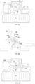
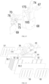
- a first embodiment of the phase-pole arc-extinguishing system 94 is shown: in the phase-pole arc-extinguishing system 94 in the first embodiment, the arc-striking member main body 50-0 is of an inverted V-shaped structure, both ends of the arc-striking member main body 50-0 are respectively connected to the primary arc-striking plate 50-1 of the arc-striking member and the secondary striking plate 50-2 of the arc-striking member, and a bend of the inverted V-shaped structure of the arc-striking member main body 50-0 is an arc-striking end.
- the arc-striking member main body 50-0 includes an arc runway structure 50-01 that is respectively connected with the primary arc-striking plate 50-1 of the arc-striking member and the secondary arc-striking plate 50-2 of the arc-striking member;
- the arc runway structure 50-01 includes an arc running plate 50-010 and an arc running plate connecting portion 50-011 which are arranged side by side at intervals; the respective arc running plates 50-010 are connected end-to-end through the arc running plate connecting portion 50-011; and the arc runway structure is preferably formed into a serpentine line structure.
- the arc running plates 50-010 are arranged in parallel to each other, and the arc running plate connecting portion 50-011 is preferably of an arc-shaped plate structure.
- a U-shaped arc-extinguishing chamber 50-012 is formed between every two adjacent arc running plates 50-010. Open ends of the respective U-shaped arc-extinguishing chambers 50-012 alternately face the electric arc inlets of the primary arc-extinguishing chamber 94-1 and the secondary arc-extinguishing chamber 94-2.
- a plane where the arc running plate 50-010 is located is located is parallel to a plane where the arc-extinguishing grids 490 of the primary arc-extinguishing chamber 94-1 and the secondary arc-extinguishing chamber 94-2 are located.
- At least one of the first main body portion 50-0a and the second main body portion 50-0b is provided with the arc runway structure 50-01. Further, the first main body portion 50-0a and the second main body portion 50-0b are both provided with the arc runway structure 50-01. Further, the first main body portion 50-0a and the second main body portion 50-0b are symmetrical structures with each other.
- the arc-striking member main body 50-0 further includes a main body cap 50-00 of the inverted V-shaped structure, both ends of the main body cap 50-00 are connected to the first main body portion 50-0a and the second main body portion 50-0b of the arc-striking member main body 50-00 respectively, and a bend in the middle of the main body cap is an arc-striking end.
- the arc running plate 50-010, connected to the main body cap 50-00, of the arc runway structure 50-01 of the first main body portion 50-0a is a first arc running plate
- the arc running plate 50-010, connected to the main body cap 50-00, of the second main body portion 50-0b is a second arc running plate.
- the first arc running plate and the second arc running plate are coplanar.
- One end of the first arc running plate close to the primary arc-extinguishing chamber 94-1 and one end of the second arc running plate close to the secondary arc-extinguishing chamber 94-2 are respectively connected to both ends of the main body cap 50-00.
- one end of the first arc running plate and one end of the second arc running plate, which are opposite, are connected to both ends of the main body cap 50-00 respectively; and an opening of the V-shaped structure of the main body cap 50-00 is opposite to a gap between the first main body portion 50-0a and the second main body portion 50-0b.
- the first main body portion 50-0a and the second main body portion 50-0b are respectively connected to the primary arc-striking plate 50-1 of the arc-striking member and the secondary arc-striking plate 50-2 of the arc-striking member through an arc-striking portion transition portion 50-02.
- one ends of the arc running plates 50-010 away from the corresponding arc-extinguishing chamber are flush; a spacing between one end of each arc running plate 50-010 close to the corresponding arc-extinguishing chamber and the corresponding arc-extinguishing chamber, from the arc running plate 50-010 of the main body cap 50-00 (or the phase-pole contact system 93) to the arc running plate 50-010 away from the main body cap 50-00 (or the phase-pole contact system 93), gradually decreases.
- one ends of the arc running plates 50-010 of one set of arc runway structures 50-01 close to the other set of arc runway structures 50-01 are flush; and a spacing between the other end of one end of each arc running plate 50-010 and the corresponding arc-extinguishing chamber gradually decreases from one side of the main body cap 50-00 to the other side.
- the arc-striking member main body 50-0 integrally forms a pagoda-like structure.
- a third embodiment of the phase-pole arc-extinguishing system 94 is shown, which is different from the second embodiment in that: in the phase-pole arc-extinguishing system 94 in the third embodiment, a plane where the arc running plate 50-010 of the arc-striking member 50 is located is perpendicular to a plane where the arc-extinguishing grids 490 of the primary arc-extinguishing chamber 94-1 and the secondary arc-extinguishing chamber 94-2 are located; the adjacent two arc running plates 50-010 of the first main body portion 50-0a and the second main body portion 50-0b are central arc running plates; one ends of the two central arc running plates close to the phase-pole contact system 93 are flush, protrude toward a side where the phase-pole contact system 93 is located relative to the rest arc running plates 50-010, and are connected through a arc running plate connecting portion 50-011 which is a central arc running plate connecting portion 50-011 which is
- the openings of the respective U-shaped arc-extinguishing cavities 50-012 alternately face a side where the phase-pole contact system 93 is located and a side where the primary arc-striking plate 50-1 of the arc-striking member and the secondary arc-striking plate 50-2 of the arc-striking member are located.
- the previous one faces a side where the phase-pole contact system 93 is located, and the next one faces a side where the primary arc-striking plate 50-1 of the arc-striking member and the secondary arc-striking plate 50-2 of the arc-striking member are located; or the previous one faces a side where the primary arc-striking plate 50-1 of the arc-striking member and the secondary arc-striking plate 50-2 of the arc-striking member are located, and the next one faces a side where the phase-pole contact system 93 is located.
- an expansion length of the arc-striking member main body 50-0 determines actual arc-extinguishing and arc-striking effects. With the increase of the length of the arc runway structure 50-01, an arc voltage also increases, so the expansion length of the arc-striking member main body 50-0 should be increased as much as possible in the case of not extending a space allowed.
- each arc running plate 50-010 close to the phase-pole contact system 93 gradually shifts to a side away from the phase-pole contact system 93. That is, in a direction as shown in FIG. 17a , from the two central arc plates to both sides, the upper end of each arc running plate 50-010 gradually shifts downward.
Landscapes
- Physics & Mathematics (AREA)
- Electromagnetism (AREA)
- Breakers (AREA)
- Driving Mechanisms And Operating Circuits Of Arc-Extinguishing High-Tension Switches (AREA)
Applications Claiming Priority (2)
| Application Number | Priority Date | Filing Date | Title |
|---|---|---|---|
| CN202211283677.1A CN117954287B (zh) | 2022-10-20 | 2022-10-20 | 断路器的操作机构 |
| PCT/CN2023/124631 WO2024083053A1 (zh) | 2022-10-20 | 2023-10-14 | 断路器的操作机构及断路器 |
Publications (2)
| Publication Number | Publication Date |
|---|---|
| EP4528780A1 true EP4528780A1 (de) | 2025-03-26 |
| EP4528780A4 EP4528780A4 (de) | 2026-05-06 |
Family
ID=90736895
Family Applications (1)
| Application Number | Title | Priority Date | Filing Date |
|---|---|---|---|
| EP23879042.2A Pending EP4528780A4 (de) | 2022-10-20 | 2023-10-14 | Schutzschalterbetriebsmechanismus und schutzschalter |
Country Status (5)
| Country | Link |
|---|---|
| US (1) | US20250372330A1 (de) |
| EP (1) | EP4528780A4 (de) |
| CN (1) | CN117954287B (de) |
| MX (1) | MX2024011570A (de) |
| WO (1) | WO2024083053A1 (de) |
Families Citing this family (3)
| Publication number | Priority date | Publication date | Assignee | Title |
|---|---|---|---|---|
| CN118398452B (zh) * | 2024-06-28 | 2024-08-30 | 浙江天正电气股份有限公司 | 一种快速脱扣机构 |
| CN119314826B (zh) * | 2024-12-17 | 2025-03-18 | 浙江金莱勒电气股份有限公司 | 一种隔离开关的操作机构及其生产工艺 |
| CN120998727B (zh) * | 2025-10-24 | 2026-01-23 | 天水长城开关厂集团有限公司 | 一种高压六氟化硫断路器驱动结构 |
Family Cites Families (9)
| Publication number | Priority date | Publication date | Assignee | Title |
|---|---|---|---|---|
| GB498376A (en) * | 1937-07-20 | 1939-01-06 | Schiele Industriewerke | Improvements in, and connected with, overload-released contact mechanism for automatic electric switches |
| US4639700A (en) * | 1986-02-19 | 1987-01-27 | Westinghouse Electric Corp. | Circuit interrupter with shock resistant mechanism |
| CN101604601B (zh) * | 2009-06-05 | 2012-10-03 | 上海诺雅克电气有限公司 | 具有气压致动脱扣功能的快速跳闸断路器 |
| CN102386031A (zh) * | 2011-12-05 | 2012-03-21 | 合隆防爆电气有限公司 | 断路器的操作机构以及带有该操作机构的断路器 |
| CN204614745U (zh) * | 2015-04-28 | 2015-09-02 | 上海电科电器科技有限公司 | 断路器的操作机构的锁扣装置 |
| CN208400795U (zh) * | 2017-12-22 | 2019-01-18 | 上海诺雅克电气有限公司 | 断路器 |
| CN211654742U (zh) * | 2019-12-14 | 2020-10-09 | 浙江正泰电器股份有限公司 | 断路器的操作机构 |
| CN113035651B (zh) * | 2021-02-05 | 2025-07-01 | 真兰电气(上海)有限公司 | 断路器的操作机构及断路器 |
| CN216749781U (zh) * | 2021-08-20 | 2022-06-14 | 上海正泰智能科技有限公司 | 断路器的操作机构及断路器 |
-
2022
- 2022-10-20 CN CN202211283677.1A patent/CN117954287B/zh active Active
-
2023
- 2023-10-14 WO PCT/CN2023/124631 patent/WO2024083053A1/zh not_active Ceased
- 2023-10-14 MX MX2024011570A patent/MX2024011570A/es unknown
- 2023-10-14 EP EP23879042.2A patent/EP4528780A4/de active Pending
- 2023-10-14 US US18/877,840 patent/US20250372330A1/en active Pending
Also Published As
| Publication number | Publication date |
|---|---|
| US20250372330A1 (en) | 2025-12-04 |
| CN117954287B (zh) | 2024-10-29 |
| CN117954287A (zh) | 2024-04-30 |
| EP4528780A4 (de) | 2026-05-06 |
| WO2024083053A1 (zh) | 2024-04-25 |
| MX2024011570A (es) | 2024-09-26 |
Similar Documents
| Publication | Publication Date | Title |
|---|---|---|
| EP4528780A1 (de) | Schutzschalterbetriebsmechanismus und schutzschalter | |
| EP4181166B1 (de) | Schutzschalter | |
| US12431312B2 (en) | Operating mechanism of circuit breaker | |
| CN213184182U (zh) | 开关电器 | |
| US12603241B2 (en) | Circuit breaker and operating mechanism thereof | |
| US12412719B2 (en) | Operating mechanism of circuit breaker, and circuit breaker | |
| US12400815B2 (en) | Moving contact mechanism | |
| EP4528777A1 (de) | Betätigungsmechanismus eines schutzschalters, schnellauslösevorrichtung und schutzschalter | |
| CN114551131A (zh) | 直流电灭弧装置和电机式直流电开关设备 | |
| CN113972118B (zh) | 开关电器 | |
| CN101562102A (zh) | 断路器的接触组件 | |
| CN216749781U (zh) | 断路器的操作机构及断路器 | |
| CN117954293A (zh) | 断路器 | |
| CN220172023U (zh) | 插入式断路器 | |
| CN113936978A (zh) | 一种塑壳断路器 | |
| CN214227362U (zh) | 环网柜及其三工位开关 | |
| CN223743580U (zh) | 静触头结构 | |
| CN222914718U (zh) | 灭弧系统和断路器 | |
| CN223513887U (zh) | 操作装置 | |
| CN116978752A (zh) | 一种塑壳断路器结构和塑壳断路器 | |
| RU2404476C1 (ru) | Многополюсный автоматический выключатель | |
| CN220155471U (zh) | 热磁脱扣机构 | |
| CN119381219B (zh) | 一种直动式单极双断点直流框架断路器 | |
| CN222168232U (zh) | 一种直流隔离开关 | |
| CN221861569U (zh) | 一种电的融合保护电器 |
Legal Events
| Date | Code | Title | Description |
|---|---|---|---|
| STAA | Information on the status of an ep patent application or granted ep patent |
Free format text: STATUS: THE INTERNATIONAL PUBLICATION HAS BEEN MADE |
|
| PUAI | Public reference made under article 153(3) epc to a published international application that has entered the european phase |
Free format text: ORIGINAL CODE: 0009012 |
|
| STAA | Information on the status of an ep patent application or granted ep patent |
Free format text: STATUS: REQUEST FOR EXAMINATION WAS MADE |
|
| 17P | Request for examination filed |
Effective date: 20241218 |
|
| AK | Designated contracting states |
Kind code of ref document: A1 Designated state(s): AL AT BE BG CH CY CZ DE DK EE ES FI FR GB GR HR HU IE IS IT LI LT LU LV MC ME MK MT NL NO PL PT RO RS SE SI SK SM TR |
|
| DAV | Request for validation of the european patent (deleted) | ||
| DAX | Request for extension of the european patent (deleted) |