EP4528932A1 - Réflecteur d'antenne à surface rayonnante réglable - Google Patents
Réflecteur d'antenne à surface rayonnante réglable Download PDFInfo
- Publication number
- EP4528932A1 EP4528932A1 EP23382964.7A EP23382964A EP4528932A1 EP 4528932 A1 EP4528932 A1 EP 4528932A1 EP 23382964 A EP23382964 A EP 23382964A EP 4528932 A1 EP4528932 A1 EP 4528932A1
- Authority
- EP
- European Patent Office
- Prior art keywords
- radiating surface
- rear structure
- reflector
- bars
- respect
- Prior art date
- Legal status (The legal status is an assumption and is not a legal conclusion. Google has not performed a legal analysis and makes no representation as to the accuracy of the status listed.)
- Withdrawn
Links
Images


Classifications
-
- H—ELECTRICITY
- H01—ELECTRIC ELEMENTS
- H01Q—ANTENNAS, i.e. RADIO AERIALS
- H01Q15/00—Devices for reflection, refraction, diffraction or polarisation of waves radiated from an antenna, e.g. quasi-optical devices
- H01Q15/14—Reflecting surfaces; Equivalent structures
- H01Q15/147—Reflecting surfaces; Equivalent structures provided with means for controlling or monitoring the shape of the reflecting surface
-
- H—ELECTRICITY
- H01—ELECTRIC ELEMENTS
- H01Q—ANTENNAS, i.e. RADIO AERIALS
- H01Q15/00—Devices for reflection, refraction, diffraction or polarisation of waves radiated from an antenna, e.g. quasi-optical devices
- H01Q15/14—Reflecting surfaces; Equivalent structures
- H01Q15/16—Reflecting surfaces; Equivalent structures curved in two dimensions [2D], e.g. paraboloidal
-
- H—ELECTRICITY
- H01—ELECTRIC ELEMENTS
- H01Q—ANTENNAS, i.e. RADIO AERIALS
- H01Q15/00—Devices for reflection, refraction, diffraction or polarisation of waves radiated from an antenna, e.g. quasi-optical devices
- H01Q15/14—Reflecting surfaces; Equivalent structures
- H01Q15/141—Apparatus or processes specially adapted for manufacturing reflecting surfaces
- H01Q15/142—Apparatus or processes specially adapted for manufacturing reflecting surfaces using insulating material for supporting the reflecting surface
- H01Q15/144—Apparatus or processes specially adapted for manufacturing reflecting surfaces using insulating material for supporting the reflecting surface with a honeycomb, cellular or foamed sandwich structure
Definitions
- the European Space Agency launched the Planck satellite into orbit to study the cosmic microwave background within the scientific program Horizon 2000.
- the satellite was equipped with two instruments, LFI (Low Frequency Instrument) and HFI (High Frequency Instrument), which together covered a very wide range of the frequency spectrum of almost 830 GHz.
- the satellite manufactured by Astrium had two reflectors, a primary one and a secondary one, both composed of a honeycomb sandwich panel core made of carbon fiber covered by a layer of carbon fiber, having 1.5 m and 1 m in diameter respectively.
- a surface error range of 7.5 - 50 microns was established for the manufacture of the reflectors.
- the EarthCARE Earth Clouds, Aerosols, and Radiation Explorer
- the Objective of which is to improve knowledge about the interaction between clouds, aerosols and radiation to generate future models that are capable of exactly predicting climate changes, launched a satellite with 4 measuring instruments into orbit.
- One of these instruments called Cloud Profiling Radar, was equipped with a deployable reflector having 2.5 m in diameter.
- the antenna reflector having adjustable radiating surface proposed by the present invention allows fine geometric adjustment of the radiating surface of the reflector at multiple points with an accuracy of the order of 0.001 mm after the reflector assembly has been manufactured and thermally stabilized.
- the reflector is made up of a sandwich panel rear structure made of composite material, a monolithic radiating surface formed by a sheet made of composite material separated from the rear structure and a set of bars uniformly distributed between the rear structure and the radiating surface, which, by one of the ends thereof, supports the radiating surface in multiple contact areas with respect to the rear structure.
- Each of said bars in contact with the radiating surface is movable perpendicularly with respect to the rear structure, so the distance of each contact area of the radiating surface with respect to the rear structure can be controlled, in order to achieve the desired uniform curvature across the entire radiating surface with a surface average that can be of the order of one micron.
- Each of the bars is equipped with an outer end and an inner end, wherein the inner end supports the radiating surface in multiple contact areas with respect to the rear structure.
- the bars move longitudinally, preferably by means of corresponding actuators, which can be mechanical or other types, which are linked to the rear structure at multiple points and which define in the movement thereof the extension or retraction of each bar depending on the position to be reached for each contact area of the radiating surface in order to achieve a uniform curvature of said radiating surface with a minimum dimensional error with respect to the desired surface.
- corresponding actuators which can be mechanical or other types, which are linked to the rear structure at multiple points and which define in the movement thereof the extension or retraction of each bar depending on the position to be reached for each contact area of the radiating surface in order to achieve a uniform curvature of said radiating surface with a minimum dimensional error with respect to the desired surface.
- the radiating surface is adjusted on the ground before launch or operation, then it is measured using laser trackers, and once the shape of the radiating surface is adjusted to the required measurement, the bars are fixed in position by means of joining means, such as an adhesive or similar, the actuators are then removed, and the excess sections of the bars are trimmed and flushed with the subsequent structure. This makes it possible to achieve a lighter, more stable and accurate structure than in other embodiments.
- the reflector is launched into space with the actuators, and these are controlled remotely, allowing the radiating surface of the reflector to be adjusted once same is in orbit or in operation.
- the rear structure and the rest of the elements behind the radiating surface are designed with dimensions such that they are invisible to the magnetic field, so the magnetic field is not affected by any interaction.
- the reflector can incorporate reinforcements in the rear structure that give it greater rigidity and stability.
- the reflector can have a film or layer of paint or surface finish on the reflective surface that reduces electrical losses in the normal operation of its radiating surface.
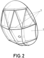
- the antenna reflector comprises a composite sandwich panel rear structure (1), a reflective monolithic radiating surface (2) formed by a sheet made of composite material separated from the rear structure (1) and a set of bars (3) uniformly distributed between the rear structure (1) and the radiating surface (2), wherein each of the bars (3) supports the radiating surface (2) by one of the ends thereof in multiple areas of contact with respect to the rear structure (1).
- Figure 1 shows that the bars (3) are longitudinally movable by the action of actuators (4) linked to the rear structure (1) to control the distance of each contact area of the radiating surface (2) with respect to the rear structure (1) in order to achieve the required shape of the entire radiating surface (2) within micrometric tolerances.
- FIG. 1 shows that, coupled to one of the ends of the bars (3), plates (5) can be located forming the support surface of the different areas of the radiating surface (2), on which the bars (3) act in the extension or retraction movement thereof depending on the position of the radiating surface (2) to be reached for each of its areas in relation to the adjacent areas in order to minimize the geometric error of the entire radiating surface (2).
- the reflector with the actuators (4) thus mounted is ready to be launched into space when a remote regulation of the position of the radiating surface is to be performed.
- figure 3 shows the reflector in which the actuators (4) have been disassembled, the bars (3) have been trimmed by the excess inner sections thereof, as can be seen in the detail, and said bars (3) have been fixed to the radiating surface (2) and to the rear structure (1) in the optimal extension position by means of joining means such as an adhesive or similar.
- the reflector thus released from the actuators (4) is ready for launch into space.
- the figures, especially Figure 2 show that the reflector comprises reinforcements (7) on the rear structure (1) that give it greater rigidity and stability.
- the reflector incorporates a layer (6) of film or paint or surface finish having minimum tolerance on the radiating surface (2), as can be seen in the detail of Figure 3 , which reduces electrical losses in the normal operation of its radiant surface (2).
Landscapes
- Physics & Mathematics (AREA)
- Electromagnetism (AREA)
- Aerials With Secondary Devices (AREA)
Priority Applications (1)
| Application Number | Priority Date | Filing Date | Title |
|---|---|---|---|
| EP23382964.7A EP4528932A1 (fr) | 2023-09-22 | 2023-09-22 | Réflecteur d'antenne à surface rayonnante réglable |
Applications Claiming Priority (1)
| Application Number | Priority Date | Filing Date | Title |
|---|---|---|---|
| EP23382964.7A EP4528932A1 (fr) | 2023-09-22 | 2023-09-22 | Réflecteur d'antenne à surface rayonnante réglable |
Publications (1)
| Publication Number | Publication Date |
|---|---|
| EP4528932A1 true EP4528932A1 (fr) | 2025-03-26 |
Family
ID=88837600
Family Applications (1)
| Application Number | Title | Priority Date | Filing Date |
|---|---|---|---|
| EP23382964.7A Withdrawn EP4528932A1 (fr) | 2023-09-22 | 2023-09-22 | Réflecteur d'antenne à surface rayonnante réglable |
Country Status (1)
| Country | Link |
|---|---|
| EP (1) | EP4528932A1 (fr) |
Citations (3)
| Publication number | Priority date | Publication date | Assignee | Title |
|---|---|---|---|---|
| US4750002A (en) * | 1986-09-12 | 1988-06-07 | Harris Corporation | Antenna panel having adjustable supports to improve surface accuracy |
| EP2040330A1 (fr) * | 2007-09-21 | 2009-03-25 | Agence Spatiale Europeenne | Réflecteur reconfigurable pour ondes électromagnétiques |
| US10241321B1 (en) * | 2015-05-06 | 2019-03-26 | Sciperio, Inc | Monolithic adaptive optical/RF reflector |
-
2023
- 2023-09-22 EP EP23382964.7A patent/EP4528932A1/fr not_active Withdrawn
Patent Citations (3)
| Publication number | Priority date | Publication date | Assignee | Title |
|---|---|---|---|---|
| US4750002A (en) * | 1986-09-12 | 1988-06-07 | Harris Corporation | Antenna panel having adjustable supports to improve surface accuracy |
| EP2040330A1 (fr) * | 2007-09-21 | 2009-03-25 | Agence Spatiale Europeenne | Réflecteur reconfigurable pour ondes électromagnétiques |
| US10241321B1 (en) * | 2015-05-06 | 2019-03-26 | Sciperio, Inc | Monolithic adaptive optical/RF reflector |
Similar Documents
| Publication | Publication Date | Title |
|---|---|---|
| Chandra et al. | A review on developments of deployable membrane-based reflector antennas | |
| Hodges et al. | An extremely large Ka-band reflectarray antenna for interferometric synthetic aperture radar: Enabling next-generation satellite remote sensing | |
| Meguro et al. | Key technologies for high-accuracy large mesh antenna reflectors | |
| Güsten et al. | The Atacama Pathfinder EXperiment (APEX)–a new submillimeter facility for southern skies– | |
| Duan et al. | Large deployable satellite antennas | |
| Chahat et al. | Deployable one-meter reflectarray for 6U-class CubeSats | |
| Quadrelli et al. | Distributed swarm antenna arrays for deep space applications | |
| Baars | Metrology of reflector antennas: A historical review | |
| EP4528932A1 (fr) | Réflecteur d'antenne à surface rayonnante réglable | |
| Wang et al. | Inflatable antenna for space-borne microwave remote sensing | |
| Hedgepeth | Structures for remotely deployable precision antennas | |
| Chahat et al. | One meter deployable reflectarray antenna for earth science radars | |
| Güsten et al. | APEX: the Atacama pathfinder experiment | |
| Mancini et al. | Uncertainty Quantification Analysis for a Ka-band Deployable Mesh Reflector for INCUS | |
| Hallibert | Technologies for future large optical missions: an ESA perspective | |
| Hodges et al. | S-Band Reflectarray Antenna for Venus Synthetic Aperture Radar and Radiometer | |
| Pearson et al. | Thin film antenna development and optimization | |
| Schulze et al. | Enabling antenna systems for extreme deep-space mission applications | |
| Davis et al. | Mechanical development of antenna systems | |
| Rincon et al. | The P-Band Space Exploration Synthetic Aperture Radar (SESAR) | |
| Hodges et al. | Ka-band reflectarray for interferometric SAR altimeter | |
| Klenk et al. | Impacts of expectable large deployable reflector deformations on digital beamforming | |
| Hodges et al. | A reflectarray antenna for use in interferometeric ocean height measurement | |
| Imbriale et al. | Thermal considerations for hydroformed reflectors | |
| Tanaka | High precision shape control based on surface accuracy analyses using an optical shape measurement system |
Legal Events
| Date | Code | Title | Description |
|---|---|---|---|
| PUAI | Public reference made under article 153(3) epc to a published international application that has entered the european phase |
Free format text: ORIGINAL CODE: 0009012 |
|
| STAA | Information on the status of an ep patent application or granted ep patent |
Free format text: STATUS: THE APPLICATION HAS BEEN PUBLISHED |
|
| AK | Designated contracting states |
Kind code of ref document: A1 Designated state(s): AL AT BE BG CH CY CZ DE DK EE ES FI FR GB GR HR HU IE IS IT LI LT LU LV MC ME MK MT NL NO PL PT RO RS SE SI SK SM TR |
|
| STAA | Information on the status of an ep patent application or granted ep patent |
Free format text: STATUS: THE APPLICATION IS DEEMED TO BE WITHDRAWN |
|
| 18D | Application deemed to be withdrawn |
Effective date: 20250927 |