EP4529015A1 - Procédé de régulation de tension pour un onduleur triphasé à trois niveaux à quatre branches de pont - Google Patents
Procédé de régulation de tension pour un onduleur triphasé à trois niveaux à quatre branches de pont Download PDFInfo
- Publication number
- EP4529015A1 EP4529015A1 EP23871060.2A EP23871060A EP4529015A1 EP 4529015 A1 EP4529015 A1 EP 4529015A1 EP 23871060 A EP23871060 A EP 23871060A EP 4529015 A1 EP4529015 A1 EP 4529015A1
- Authority
- EP
- European Patent Office
- Prior art keywords
- vectors
- voltage
- bridge
- reference voltage
- voltage vectors
- Prior art date
- Legal status (The legal status is an assumption and is not a legal conclusion. Google has not performed a legal analysis and makes no representation as to the accuracy of the status listed.)
- Pending
Links
Images


Classifications
-
- H—ELECTRICITY
- H02—GENERATION; CONVERSION OR DISTRIBUTION OF ELECTRIC POWER
- H02M—APPARATUS FOR CONVERSION BETWEEN AC AND AC, BETWEEN AC AND DC, OR BETWEEN DC AND DC, AND FOR USE WITH MAINS OR SIMILAR POWER SUPPLY SYSTEMS; CONVERSION OF DC OR AC INPUT POWER INTO SURGE OUTPUT POWER; CONTROL OR REGULATION THEREOF
- H02M7/00—Conversion of AC power input into DC power output; Conversion of DC power input into AC power output
- H02M7/42—Conversion of DC power input into AC power output without possibility of reversal
- H02M7/44—Conversion of DC power input into AC power output without possibility of reversal by static converters
- H02M7/48—Conversion of DC power input into AC power output without possibility of reversal by static converters using discharge tubes with control electrode or semiconductor devices with control electrode
- H02M7/483—Converters with outputs that each can have more than two voltages levels
- H02M7/487—Neutral point clamped inverters
-
- H—ELECTRICITY
- H02—GENERATION; CONVERSION OR DISTRIBUTION OF ELECTRIC POWER
- H02M—APPARATUS FOR CONVERSION BETWEEN AC AND AC, BETWEEN AC AND DC, OR BETWEEN DC AND DC, AND FOR USE WITH MAINS OR SIMILAR POWER SUPPLY SYSTEMS; CONVERSION OF DC OR AC INPUT POWER INTO SURGE OUTPUT POWER; CONTROL OR REGULATION THEREOF
- H02M7/00—Conversion of AC power input into DC power output; Conversion of DC power input into AC power output
- H02M7/42—Conversion of DC power input into AC power output without possibility of reversal
- H02M7/44—Conversion of DC power input into AC power output without possibility of reversal by static converters
- H02M7/48—Conversion of DC power input into AC power output without possibility of reversal by static converters using discharge tubes with control electrode or semiconductor devices with control electrode
- H02M7/483—Converters with outputs that each can have more than two voltages levels
- H02M7/4833—Capacitor voltage balancing
-
- H—ELECTRICITY
- H02—GENERATION; CONVERSION OR DISTRIBUTION OF ELECTRIC POWER
- H02M—APPARATUS FOR CONVERSION BETWEEN AC AND AC, BETWEEN AC AND DC, OR BETWEEN DC AND DC, AND FOR USE WITH MAINS OR SIMILAR POWER SUPPLY SYSTEMS; CONVERSION OF DC OR AC INPUT POWER INTO SURGE OUTPUT POWER; CONTROL OR REGULATION THEREOF
- H02M7/00—Conversion of AC power input into DC power output; Conversion of DC power input into AC power output
- H02M7/42—Conversion of DC power input into AC power output without possibility of reversal
- H02M7/44—Conversion of DC power input into AC power output without possibility of reversal by static converters
- H02M7/48—Conversion of DC power input into AC power output without possibility of reversal by static converters using discharge tubes with control electrode or semiconductor devices with control electrode
- H02M7/53—Conversion of DC power input into AC power output without possibility of reversal by static converters using discharge tubes with control electrode or semiconductor devices with control electrode using devices of a triode or transistor type requiring continuous application of a control signal
- H02M7/537—Conversion of DC power input into AC power output without possibility of reversal by static converters using discharge tubes with control electrode or semiconductor devices with control electrode using devices of a triode or transistor type requiring continuous application of a control signal using semiconductor devices only, e.g. single switched pulse inverters
- H02M7/5387—Conversion of DC power input into AC power output without possibility of reversal by static converters using discharge tubes with control electrode or semiconductor devices with control electrode using devices of a triode or transistor type requiring continuous application of a control signal using semiconductor devices only, e.g. single switched pulse inverters in a bridge configuration
- H02M7/53871—Conversion of DC power input into AC power output without possibility of reversal by static converters using discharge tubes with control electrode or semiconductor devices with control electrode using devices of a triode or transistor type requiring continuous application of a control signal using semiconductor devices only, e.g. single switched pulse inverters in a bridge configuration with automatic control of output voltage or current
-
- H—ELECTRICITY
- H02—GENERATION; CONVERSION OR DISTRIBUTION OF ELECTRIC POWER
- H02M—APPARATUS FOR CONVERSION BETWEEN AC AND AC, BETWEEN AC AND DC, OR BETWEEN DC AND DC, AND FOR USE WITH MAINS OR SIMILAR POWER SUPPLY SYSTEMS; CONVERSION OF DC OR AC INPUT POWER INTO SURGE OUTPUT POWER; CONTROL OR REGULATION THEREOF
- H02M7/00—Conversion of AC power input into DC power output; Conversion of DC power input into AC power output
- H02M7/42—Conversion of DC power input into AC power output without possibility of reversal
- H02M7/44—Conversion of DC power input into AC power output without possibility of reversal by static converters
- H02M7/48—Conversion of DC power input into AC power output without possibility of reversal by static converters using discharge tubes with control electrode or semiconductor devices with control electrode
- H02M7/53—Conversion of DC power input into AC power output without possibility of reversal by static converters using discharge tubes with control electrode or semiconductor devices with control electrode using devices of a triode or transistor type requiring continuous application of a control signal
- H02M7/537—Conversion of DC power input into AC power output without possibility of reversal by static converters using discharge tubes with control electrode or semiconductor devices with control electrode using devices of a triode or transistor type requiring continuous application of a control signal using semiconductor devices only, e.g. single switched pulse inverters
- H02M7/5387—Conversion of DC power input into AC power output without possibility of reversal by static converters using discharge tubes with control electrode or semiconductor devices with control electrode using devices of a triode or transistor type requiring continuous application of a control signal using semiconductor devices only, e.g. single switched pulse inverters in a bridge configuration
- H02M7/53871—Conversion of DC power input into AC power output without possibility of reversal by static converters using discharge tubes with control electrode or semiconductor devices with control electrode using devices of a triode or transistor type requiring continuous application of a control signal using semiconductor devices only, e.g. single switched pulse inverters in a bridge configuration with automatic control of output voltage or current
- H02M7/53875—Conversion of DC power input into AC power output without possibility of reversal by static converters using discharge tubes with control electrode or semiconductor devices with control electrode using devices of a triode or transistor type requiring continuous application of a control signal using semiconductor devices only, e.g. single switched pulse inverters in a bridge configuration with automatic control of output voltage or current with analogue control of three-phase output
- H02M7/53876—Conversion of DC power input into AC power output without possibility of reversal by static converters using discharge tubes with control electrode or semiconductor devices with control electrode using devices of a triode or transistor type requiring continuous application of a control signal using semiconductor devices only, e.g. single switched pulse inverters in a bridge configuration with automatic control of output voltage or current with analogue control of three-phase output based on synthesising a desired voltage vector via the selection of appropriate fundamental voltage vectors, and corresponding dwelling times
-
- H—ELECTRICITY
- H02—GENERATION; CONVERSION OR DISTRIBUTION OF ELECTRIC POWER
- H02M—APPARATUS FOR CONVERSION BETWEEN AC AND AC, BETWEEN AC AND DC, OR BETWEEN DC AND DC, AND FOR USE WITH MAINS OR SIMILAR POWER SUPPLY SYSTEMS; CONVERSION OF DC OR AC INPUT POWER INTO SURGE OUTPUT POWER; CONTROL OR REGULATION THEREOF
- H02M7/00—Conversion of AC power input into DC power output; Conversion of DC power input into AC power output
- H02M7/42—Conversion of DC power input into AC power output without possibility of reversal
- H02M7/44—Conversion of DC power input into AC power output without possibility of reversal by static converters
- H02M7/48—Conversion of DC power input into AC power output without possibility of reversal by static converters using discharge tubes with control electrode or semiconductor devices with control electrode
- H02M7/53—Conversion of DC power input into AC power output without possibility of reversal by static converters using discharge tubes with control electrode or semiconductor devices with control electrode using devices of a triode or transistor type requiring continuous application of a control signal
- H02M7/537—Conversion of DC power input into AC power output without possibility of reversal by static converters using discharge tubes with control electrode or semiconductor devices with control electrode using devices of a triode or transistor type requiring continuous application of a control signal using semiconductor devices only, e.g. single switched pulse inverters
- H02M7/539—Conversion of DC power input into AC power output without possibility of reversal by static converters using discharge tubes with control electrode or semiconductor devices with control electrode using devices of a triode or transistor type requiring continuous application of a control signal using semiconductor devices only, e.g. single switched pulse inverters with automatic control of output wave form or frequency
- H02M7/5395—Conversion of DC power input into AC power output without possibility of reversal by static converters using discharge tubes with control electrode or semiconductor devices with control electrode using devices of a triode or transistor type requiring continuous application of a control signal using semiconductor devices only, e.g. single switched pulse inverters with automatic control of output wave form or frequency by pulse-width modulation
Definitions
- the present application relates to the field of electronic technologies, in particular to a voltage regulation method for a three-phase four-bridge-arm three-level inverter.
- multi-level inverters have received a lot of attention in the occasions of medium and high voltage power, and different circuit topologies and inverter control methods have been proposed.
- the multi-level inverters have gradually entered the practical stage, and are especially relatively large in demand in the market of China.
- China's potential market demands will be transformed into actual market demands, so that medium-voltage high-power inverter products have broad market prospects.
- An embodiment of the present application provides a voltage regulation method for a three-phase four-bridge-arm three-level inverter, which is used for improving/solving the problem of midpoint voltage imbalance in a multi-level inverter in related technologies.
- the present application provides a voltage regulation method for a three-phase four-bridge-arm three-level inverter, comprising: determining a voltage vector corresponding to a three-phase voltage; constructing a controllable spatial polyhedral region on the basis of an abc three-dimensional coordinate system and the voltage vector; positioning preset reference vectors in a plurality of sub-regions of the controllable spatial polyhedral region, so as to generate reference voltage vectors corresponding to the reference vectors, wherein the reference voltage vectors are used for controlling output states of corresponding four bridge arms; sorting the reference voltage vectors with a modulation strategy in which a zero-level output state is reduced; and generating a switching pulse sequence of the bridge arms according to the sorted reference voltage vectors and a corresponding action time, so as to regulate a midpoint voltage of the three-phase four-bridge-arm three-level inverter.
- the determining a voltage vector corresponding to a three-phase voltage comprises: determining the voltage vector corresponding to the three-phase voltage according to output states of the bridge arms, the output states comprising a high level, a zero level and a low level.
- the constructing a controllable spatial polyhedral region on the basis of an abc three-dimensional coordinate system and the voltage vector comprises: standardizing the voltage vectors; and introducing the standardized voltage vectors into the abc three-dimensional coordinate system to construct the controllable spatial polyhedral region.
- U AN ⁇ represents a standardized voltage vector of the A bridge arm relative to the N bridge arm;
- U BN ⁇ represents a standardized voltage vector of the B bridge arm relative to the N bridge arm;
- U CN ⁇ represents a standardized voltage vector of the C bridge arm relative to the N bridge arm
- controllable spatial polyhedral region is a controllable dodecahedral region, the controllable dodecahedral region comprising three cubic regions constructed by standardized voltage vectors and six imagery cubic regions attached to the outer sides of the three cubic regions.
- the positioning preset reference vectors in a plurality of sub-regions of the controllable spatial polyhedral region, so as to generate reference voltage vectors corresponding to the reference vectors comprises: positioning the preset reference vectors in the cubic regions of the plurality of sub-regions of the controllable spatial polyhedral region; positioning the preset reference vectors in tetrahedral regions of the plurality of sub-regions of the controllable spatial polyhedral region; and generating reference voltage vectors corresponding to the reference vectors according to a final positioning result.
- the positioning the preset reference vectors in the tetrahedral regions of the plurality of sub-regions of the controllable spatial polyhedral region comprises: a positioned target cube is divided by three 45° sections by taking origin coordinates corresponding to the reference vectors as a reference point; distances among the three sections are calculated with the reference origin coordinates as a center to determine a tetrahedron position where the reference vector is located; and the three 45° sections comprise an a-b-axis 45° section, a c-b-axis 45° section and an a-c-axis 45° section that pass through an origin.
- the sorting the reference voltage vectors with a modulation strategy in which a zero-level output state is reduced comprises: determining a synthesis sequence of the reference voltage vectors in the controllable spatial polyhedral region; and adjusting a sequence of the reference voltage vectors with a goal of reducing a midpoint current into each bridge arm.
- the generating a switching pulse sequence of the bridge arms according to the sorted reference voltage vectors and a corresponding action time comprises: sorting the action time of the reference voltage vectors according to an arrangement mode of the sorted reference voltage vectors; allocating the sorted action time in nine segments, the nine-segment allocation being as follows: a first segment, a fifth segment and a ninth segment in nine-segment vectors are allocated in the same time period, the first segment and the ninth segment respectively occupy 1/4, the fifth segment occupies 1/2, and the remaining six segments each occupy 1/2 of the corresponding time period according to symmetry; and determining states of four bridge arms according to the voltage vectors, and allocating corresponding four switching states for each state to form a pulse sequence.
- the voltage regulation method for the three-phase four-bridge-arm three-level inverter includes: determining a voltage vector corresponding to a three-phase voltage; constructing a controllable spatial polyhedral region on the basis of an abc three-dimensional coordinate system and the voltage vector; positioning preset reference vectors in a plurality of sub-regions of the controllable spatial polyhedral region, so as to generate reference voltage vectors corresponding to the reference vectors, wherein the reference voltage vectors are used for controlling output states of corresponding four bridge arms; sorting the reference voltage vectors with a modulation strategy in which a zero-level output state is reduced; and generating a switching pulse sequence of the bridge arms according to the sorted reference voltage vectors and a corresponding action time, so as to regulate a midpoint voltage of the three-phase four-bridge-arm three-level inverter.
- the present embodiment has the following beneficial effects.
- first and second are used for descriptive purposes only and cannot be understood as indicating or implying relative importance, or implicitly indicating the number of technical features indicated thereby. Therefore, the feature defined by “first” and “second” may explicitly or implicitly include one or more of the features. In the description of the present invention, the meaning of “multiple” is two or more than two, unless otherwise specifically defined.
- a and/or B includes the following three combinations: A alone, B alone, and a combination of A and B.
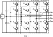
- FIG. 1 is a schematic structural diagram of a three-phase four-bridge-arm three-level inverter.
- a topological structure of the three-phase four-arm three-level inverter includes a DC-side voltage source U dc , from left to right, which are an A bridge arm, a B bridge arm, a C bridge arm and an N bridge arm respectively.
- Each bridge arm consists of four switches (e.g., IGBTs) and two diodes.
- a diode midpoint of each bridge arm is connected to a midpoint n of a split capacitor.
- a voltage of the midpoint n of the split capacitor needs to be regulated in the embodiment of the present application.
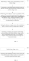
- FIG. 2 is a schematic flowchart of an embodiment of the voltage regulation method for the three-phase four-bridge-arm three-level inverter provided by the present application. The method includes the following steps 21-25.
- step 21 a voltage vector corresponding to a three-phase voltage is determined.
- the voltage vector corresponding to the three-phase voltage is determined according to output states of the bridge arms, the output states including a high level, a zero level and a low level.
- step 22 a controllable spatial polyhedral region is constructed on the basis of an abc three-dimensional coordinate system and the voltage vector.
- controllable spatial polyhedral region includes a plurality of cubic subregions and a plurality of tetrahedral subregions.
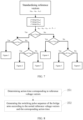
- FIG. 3 is a schematic flowchart of the step 22 in one embodiment.
- This step 22 may include the following steps 221-222.
- step 221 the voltage vectors are standardized.
- U AN ⁇ represents a standardized voltage vector of the A bridge arm relative to the N bridge arm;
- U BN ⁇ represents a standardized voltage vector of the B bridge arm relative to the N bridge arm; and
- U CN ⁇ represents a standardized voltage vector of the C bridge arm relative to the N bridge arm.
- step 222 the standardized voltage vectors are introduced into the abc three-dimensional coordinate system to construct the controllable spatial polyhedral region.
- FIG. 4 is a schematic diagram of the controllable spatial polyhedral region provided by the present application. After the voltage vectors are standardized, the standardized voltage vectors are introduced into the abc three-dimensional coordinate system to construct a controllable dodecahedral region.
- controllable spatial polyhedral region includes three large cubes and six imaginary cubes.
- Each imaginary cube is a control region within a modulation ratio range of 0.866 to 1, and the controllable region is translated to a forward direction of the abc coordinate system, which is convenient for unified analysis and calculation.
- step 23 preset reference vectors are positioned in a plurality of subregions of the controllable spatial polyhedral region, so as to generate reference voltage vectors corresponding to the reference vectors, wherein the reference voltage vectors are used for controlling output states of corresponding four bridge arms.
- FIG. 5 is a schematic flowchart of the step 23 in one embodiment.
- This step 23 may include the following steps 231-233.
- step 231 the preset reference vectors are positioned in the cubic regions of the plurality of subregions of the controllable spatial polyhedral region.
- a cube where reference origin coordinates are located are located is selected from the controllable spatial polyhedral region based on the reference origin coordinates after rounding of the reference vectors, wherein
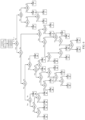
- FIG. 6 is a schematic flowchart of cube positioning provided by the present application.
- reference origin coordinate points ( a, b, c ) are calculated by using the above formula, and then a logical sequence in FIG. 6 is used to determine:
- step 232 the preset reference vectors are positioned in tetrahedral regions of the plurality of sub-regions of the controllable spatial polyhedral region.
- the positioned target cube is divided by three 45° sections by taking origin coordinates corresponding to the reference vectors as a reference point; distances among the three sections are calculated with the reference origin coordinates as a center to determine a tetrahedron position where the reference vector is located; and the three 45° sections comprise an a-b-axis 45° section, a c-b-axis 45° section and an a-c-axis 45° section that pass through an origin.
- FIG. 7 is a schematic flowchart of tetrahedron positioning provided by the present application.
- reference origin coordinate points (a, b, c) and reference vectors ( u an , u bn , u cn ) are calculated by using the above formula, and then a logical sequence in FIG. 7 is used to determine:
- step 233 reference voltage vectors corresponding to the reference vectors are generated according to a final positioning result.
- step 24 the reference voltage vectors are sorted with a modulation strategy in which a zero-level output state is reduced.
- the step 24 may specifically include: determining a synthesis sequence of the reference voltage vectors in the controllable spatial polyhedral region; and adjusting a sequence of the reference voltage vectors with the goal of reducing the midpoint current into each bridge arm.
- the new vector arrangement method is as follows (four reference voltage vectors for a tetrahedron are V1-V4):
- step 25 a switching pulse sequence of the bridge arms is generated according to the sorted reference voltage vectors and a corresponding action time, so as to regulate the midpoint voltage of the three-phase four-bridge-arm three-level inverter.
- FIG. 8 is a schematic flowchart of the step 25 in one embodiment.
- This step 25 may include the following steps 251 to 252.
- step 251 an action time corresponding to the reference voltage vectors is determined.
- the corresponding action time is T1-T4, and a sequence of the action time keeps consistent with the sequence of the above reference voltage vectors.
- step 252 the switching pulse sequence of the bridge arms is generated according to the sorted reference voltage vectors and the corresponding action time.
- the action time of the reference voltage vectors is sorted; the sorted action time is allocated in nine segments, the nine-segment allocation being as follows: a first segment, a fifth segment and a ninth segment in nine-segment vectors are allocated in the same time period, the first segment and the ninth segment respectively occupy 1/4, the fifth segment occupies 1/2, and the remaining six segments each occupy 1/2 of the corresponding time period according to symmetry (i.e., T x1 /4, T x2 /2, T x3 /2, T x4 /2, T x1 /2, T x4 /2, T x3 /2, T X2 /2, and T x1 /4); and states of four bridge arms are determined according to the voltage vectors, and corresponding four switching states are allocated for each state to form a pulse sequence.
- FIG. 9 is a schematic diagram of a nine-stage time allocation method provided by the present application.
- the nine-segment time allocation method can be used so that a plurality of vectors in the reference voltage vectors have the same action time, thus achieving the dual purposes of controlling the three-level inverter and achieving midpoint potential balance.
- the voltage regulation method for the three-phase four-bridge-arm three-level inverter includes: determining a voltage vector corresponding to a three-phase voltage; constructing a controllable spatial polyhedral region on the basis of an abc three-dimensional coordinate system and the voltage vector, the controllable spatial polyhedral region including a plurality of tetrahedral subregions and cubic subregions; positioning preset reference vectors in a plurality of subregions of the controllable spatial polyhedral region, so as to generate reference voltage vectors corresponding to the reference vectors, wherein the reference voltage vectors are used for controlling output states of corresponding four bridge arms; sorting the reference voltage vectors with a modulation strategy in which a zero-level output state is reduced; and generating a switching pulse sequence of the bridge arms according to the sorted reference voltage vectors and a corresponding action time, so as to regulate a midpoint voltage of the three-phase four-bridge-arm three-level inverter
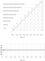
- FIG. 10 is a midpoint location diagram under a balanced load condition provided by the present application
- FIG. 11 is a midpoint location diagram under an actual load condition after balance with a voltage regulation method provided by the present application.
- a horizontal axis is time
- a vertical axis is voltages.
- the inverter power in FIG. 10 is 5 KW
- the inverter power in FIG. 11 is 100 KW.
- the midpoint voltage balance can be well maintained by the method provided in the present embodiment, and the operation can be seen to be very stable after extending the time axis.
Landscapes
- Engineering & Computer Science (AREA)
- Power Engineering (AREA)
- Inverter Devices (AREA)
Applications Claiming Priority (2)
| Application Number | Priority Date | Filing Date | Title |
|---|---|---|---|
| CN202211216528.3A CN117856639A (zh) | 2022-09-30 | 2022-09-30 | 一种三相四桥臂三电平逆变器的电压调节方法 |
| PCT/CN2023/122773 WO2024067836A1 (fr) | 2022-09-30 | 2023-09-28 | Procédé de régulation de tension pour un onduleur triphasé à trois niveaux à quatre branches de pont |
Publications (2)
| Publication Number | Publication Date |
|---|---|
| EP4529015A1 true EP4529015A1 (fr) | 2025-03-26 |
| EP4529015A4 EP4529015A4 (fr) | 2026-05-13 |
Family
ID=90476413
Family Applications (1)
| Application Number | Title | Priority Date | Filing Date |
|---|---|---|---|
| EP23871060.2A Pending EP4529015A4 (fr) | 2022-09-30 | 2023-09-28 | Procédé de régulation de tension pour un onduleur triphasé à trois niveaux à quatre branches de pont |
Country Status (4)
| Country | Link |
|---|---|
| EP (1) | EP4529015A4 (fr) |
| JP (1) | JP2025532445A (fr) |
| CN (1) | CN117856639A (fr) |
| WO (1) | WO2024067836A1 (fr) |
Families Citing this family (1)
| Publication number | Priority date | Publication date | Assignee | Title |
|---|---|---|---|---|
| CN119010626B (zh) * | 2024-10-25 | 2025-01-07 | 东北大学秦皇岛分校 | 具有低开关频率的npc四桥臂逆变器中点电位控制方法 |
Family Cites Families (9)
| Publication number | Priority date | Publication date | Assignee | Title |
|---|---|---|---|---|
| US5852558A (en) * | 1997-06-20 | 1998-12-22 | Wisconsin Alumni Research Foundation | Method and apparatus for reducing common mode voltage in multi-phase power converters |
| CN101510736B (zh) * | 2009-03-11 | 2010-12-08 | 南京航空航天大学 | 一种三相四桥臂三电平逆变器中点电位漂移抑制方法 |
| CN102647101B (zh) * | 2011-12-26 | 2015-07-08 | 东方日立(成都)电控设备有限公司 | 一种多坐标系下的三电平空间矢量调制方法 |
| CN103248304A (zh) * | 2013-04-23 | 2013-08-14 | 河南科技大学 | 一种基于简化svpwm的三电平逆变间接矢量控制系统 |
| CN104038091B (zh) * | 2014-07-04 | 2017-05-24 | 国家电网公司 | 基于svpwm的三电平变流器直流侧中点电压平衡控制方法 |
| CN104377977A (zh) * | 2014-12-08 | 2015-02-25 | 国家电网公司 | 一种三电平逆变器及其控制方法 |
| CN106385192B (zh) * | 2016-10-31 | 2020-03-31 | 东北大学秦皇岛分校 | 三电平四桥臂逆变器控制方法 |
| CN109347347B (zh) * | 2018-10-11 | 2020-05-15 | 南京航空航天大学 | 不平衡负载下三相四线制三电平逆变器通用型3d-svpwm控制方法及控制系统 |
| CN111293915B (zh) * | 2020-02-29 | 2023-03-31 | 天津工业大学 | 中点电位不平衡下的npc逆变器改进虚拟矢量调制方法 |
-
2022
- 2022-09-30 CN CN202211216528.3A patent/CN117856639A/zh active Pending
-
2023
- 2023-09-28 JP JP2024563383A patent/JP2025532445A/ja active Pending
- 2023-09-28 WO PCT/CN2023/122773 patent/WO2024067836A1/fr not_active Ceased
- 2023-09-28 EP EP23871060.2A patent/EP4529015A4/fr active Pending
Also Published As
| Publication number | Publication date |
|---|---|
| WO2024067836A1 (fr) | 2024-04-04 |
| CN117856639A (zh) | 2024-04-09 |
| JP2025532445A (ja) | 2025-10-01 |
| EP4529015A4 (fr) | 2026-05-13 |
Similar Documents
| Publication | Publication Date | Title |
|---|---|---|
| Meynard et al. | Multicell converters: basic concepts and industry applications | |
| Loh et al. | A reduced common mode hysteresis current regulation strategy for multilevel inverters | |
| CN101510736B (zh) | 一种三相四桥臂三电平逆变器中点电位漂移抑制方法 | |
| CN100468938C (zh) | 一种三电平逆变器的控制系统及方法 | |
| CN109004866B (zh) | 六边形结构的能馈型三端口级联变换器拓扑及控制方法 | |
| CN114629359B (zh) | 基于多绕组高频变压器的多端口交直流混合变换器及方法 | |
| CN106533230A (zh) | 基于简化平衡因子的三电平虚拟空间矢量均压调制方法 | |
| Zhao et al. | SVPWM for five-level active neutral-point-clamped converter based on multispace voltage vector mapping and midpoint-voltage self-balancing strategy | |
| CN102843018A (zh) | 模块化多电平换流器的可变积分双循环映射脉宽调制法 | |
| CN111953222A (zh) | 基于nlm与pwm混合调制的改进调制方法 | |
| CN112968614B (zh) | 一种风电变流器控制方法、电力设备控制装置及变流器 | |
| Jiang et al. | A nine-switch inverter with reduced leakage current for PV grid-tied systems using model-free predictive current control | |
| CN116345858B (zh) | 一种应用于中点钳位三电平逆变器的中点电位控制方法 | |
| Hassan et al. | Reactive power control by STATCOM quasi linear asymmetrical multilevel-based photovoltaic system | |
| EP0603683A2 (fr) | Convertisseur de fréquence, procédé pour le contrôler et commande de moteur utilisant un convertisseur de fréquence | |
| EP4068600A1 (fr) | Dispositif de commande pour système de conversion de puissance et son procédé de commande | |
| CN115800790A (zh) | 一种兼顾环流抑制和中点平衡的三电平变换器并联系统控制方法 | |
| CN106712561A (zh) | 级联h桥逆变器的控制方法及装置 | |
| Kadri et al. | Comparison between the most popular structures of multilevel inverters and the packed U cell structure | |
| JP2025532445A (ja) | 三相4レグ3レベルインバータの電圧調節方法 | |
| Ramasamy et al. | Three-dimensional space vector modulation strategy for capacitor balancing in split inductor neutral-point clamped multilevel inverters | |
| WO2024039339A1 (fr) | Procédé d'équilibrage d'état de charge adaptatif et tolérant aux défaillances pour systèmes de stockage d'énergie de batterie | |
| CN116722762A (zh) | 一种基于模型预测控制的飞跨电容并网逆变器控制方法 | |
| Wang et al. | A Novel 3D-SVPWM Modulation Strategy for Zerosequence Circulating Current Suppression in Threephase Four-Leg Parallel-Inverter Systems | |
| Buccella et al. | Investigation about selective harmonic elimination in unbalanced multilevel inverters |
Legal Events
| Date | Code | Title | Description |
|---|---|---|---|
| STAA | Information on the status of an ep patent application or granted ep patent |
Free format text: STATUS: THE INTERNATIONAL PUBLICATION HAS BEEN MADE |
|
| PUAI | Public reference made under article 153(3) epc to a published international application that has entered the european phase |
Free format text: ORIGINAL CODE: 0009012 |
|
| STAA | Information on the status of an ep patent application or granted ep patent |
Free format text: STATUS: REQUEST FOR EXAMINATION WAS MADE |
|
| 17P | Request for examination filed |
Effective date: 20241219 |
|
| AK | Designated contracting states |
Kind code of ref document: A1 Designated state(s): AL AT BE BG CH CY CZ DE DK EE ES FI FR GB GR HR HU IE IS IT LI LT LU LV MC ME MK MT NL NO PL PT RO RS SE SI SK SM TR |
|
| DAV | Request for validation of the european patent (deleted) | ||
| DAX | Request for extension of the european patent (deleted) | ||
| A4 | Supplementary search report drawn up and despatched |
Effective date: 20260415 |
|
| RIC1 | Information provided on ipc code assigned before grant |
Ipc: H02M 7/487 20070101AFI20260409BHEP Ipc: H02M 7/5387 20070101ALI20260409BHEP Ipc: H02M 7/483 20070101ALI20260409BHEP |