EP4529079A1 - Dispositif de traitement d'informations, système de réseau qkd, procédé de traitement d'informations et produit de programme informatique - Google Patents
Dispositif de traitement d'informations, système de réseau qkd, procédé de traitement d'informations et produit de programme informatique Download PDFInfo
- Publication number
- EP4529079A1 EP4529079A1 EP24186677.1A EP24186677A EP4529079A1 EP 4529079 A1 EP4529079 A1 EP 4529079A1 EP 24186677 A EP24186677 A EP 24186677A EP 4529079 A1 EP4529079 A1 EP 4529079A1
- Authority
- EP
- European Patent Office
- Prior art keywords
- key
- node
- encryption key
- encrypted
- information processing
- Prior art date
- Legal status (The legal status is an assumption and is not a legal conclusion. Google has not performed a legal analysis and makes no representation as to the accuracy of the status listed.)
- Pending
Links
- 230000010365 information processing Effects 0.000 title claims abstract description 49
- 238000004590 computer program Methods 0.000 title claims description 6
- 238000003672 processing method Methods 0.000 title claims description 6
- 238000012546 transfer Methods 0.000 claims abstract description 108
- 238000004891 communication Methods 0.000 claims abstract description 90
- 238000012545 processing Methods 0.000 claims abstract description 88
- 230000005540 biological transmission Effects 0.000 claims abstract description 31
- 238000000034 method Methods 0.000 claims description 30
- 230000004044 response Effects 0.000 claims description 9
- 238000010586 diagram Methods 0.000 description 31
- 238000012986 modification Methods 0.000 description 21
- 230000004048 modification Effects 0.000 description 21
- 230000006870 function Effects 0.000 description 18
- 238000012905 input function Methods 0.000 description 4
- 238000009825 accumulation Methods 0.000 description 3
- 230000000694 effects Effects 0.000 description 3
- 230000011664 signaling Effects 0.000 description 3
- 230000007423 decrease Effects 0.000 description 2
- 238000005516 engineering process Methods 0.000 description 2
- 238000007796 conventional method Methods 0.000 description 1
- 238000005538 encapsulation Methods 0.000 description 1
- 230000003287 optical effect Effects 0.000 description 1
- 239000013307 optical fiber Substances 0.000 description 1
- 230000005610 quantum mechanics Effects 0.000 description 1
- 238000006467 substitution reaction Methods 0.000 description 1
- 230000005641 tunneling Effects 0.000 description 1
Images






Classifications
-
- H—ELECTRICITY
- H04—ELECTRIC COMMUNICATION TECHNIQUE
- H04L—TRANSMISSION OF DIGITAL INFORMATION, e.g. TELEGRAPHIC COMMUNICATION
- H04L9/00—Cryptographic mechanisms or cryptographic arrangements for secret or secure communications; Network security protocols
- H04L9/08—Key distribution or management, e.g. generation, sharing or updating, of cryptographic keys or passwords
- H04L9/0816—Key establishment, i.e. cryptographic processes or cryptographic protocols whereby a shared secret becomes available to two or more parties, for subsequent use
- H04L9/0852—Quantum cryptography
- H04L9/0855—Quantum cryptography involving additional nodes, e.g. quantum relays, repeaters, intermediate nodes or remote nodes
-
- H—ELECTRICITY
- H04—ELECTRIC COMMUNICATION TECHNIQUE
- H04L—TRANSMISSION OF DIGITAL INFORMATION, e.g. TELEGRAPHIC COMMUNICATION
- H04L9/00—Cryptographic mechanisms or cryptographic arrangements for secret or secure communications; Network security protocols
- H04L9/14—Cryptographic mechanisms or cryptographic arrangements for secret or secure communications; Network security protocols using a plurality of keys or algorithms
Definitions
- Arrangements described herein relate generally to an information processing device, a QKD network system, an information processing method, and a computer program product.
- Quantum key distribution is a technology for securely sharing an encryption key between a QKD device that continuously transmits a single photon and a QKD device that receives a single photon, where the QKD devices are connected by an optical fiber link.
- An encryption key shared by the QKD is guaranteed not to be eavesdropped based on the principle of quantum mechanics.
- QKDN QKD network
- KM key management
- the shared encryption key is provided to an external application from the KM and used.
- the QKD device and the KM device may be implemented as an integrated device.
- Fig. 1A is a diagram for Exemplary Illustration 1 of a device configuration of a QKDN system 200 according to the arrangement.
- the QKDN system 200 according to the arrangement includes KMs 1-1 to 1-9, a plurality of QKDs 2, and a plurality of applications including applications 3-1 and 3-2.
- KMs 1-1 to 1-9 are not distinguished, they are simply referred to as a KM 1.
- applications 3-1 and 3-2 are not distinguished, they are simply referred to as an application 3.
- KM device is abbreviated as KM 1
- QKD device is abbreviated as QKD 2
- App the application is abbreviated as App.
- the KM 1 receives an encryption key from at least one QKD 2.
- the KM 1 holds and manages an applicable encryption key and also relays the encryption key between the KMs 1 to enable encryption key sharing between arbitrary KMs 1.
- the QKD 2 is a QKD device that executes a QKD protocol with a QKD 2 facing QKD to generate an encryption key.
- the QKD 2 is connected to the KM 1 and provides the encryption key to the KM 1.
- the application 3 is connected to the KM 1, acquires the encryption key from the KM 1, and performs cryptographic communication with another application.
- the application 3 is usually installed in the same base as the KM 1 to which the application 3 is connected. Note that a plurality of applications 3 may be connected to one KM 1.
- the KM 1 and the QKD 2 are installed in a base.
- the base is a section in which physical safety is ensured.
- a node including the KM 1 and the QKD 2 may be referred to as a trusted node.
- the trusted node is installed in each base to thereby guarantee storage of an encryption key, safety in a relay, and the like.
- the trusted node installed in each base is connected by a QKD link (quantum cryptographic communication path), so that a QKDN 100 is configured.
- Fig. 1B is a diagram illustrating an example of a key relay according to the arrangement.
- Fig. 1B illustrates an example of a case where a key is relayed in the configuration illustrated in Fig. 1A .
- Fig. 1B illustrates an example in which the application 3-1 connected to the KM 1-2 acquires an identical encryption key with the application 3-2 connected to the KM 1-8.
- the KM 1-1 and KM 1-4, the KM 1-2 and KM 1-4, the KM 1-3 and KM 1-4, the KM 1-4 and KM 1-5, the KM 1-5 and KM 1-6, the KM 1-6 and KM 1-7, the KM 1-6 and KM 1-8, and the KM 1-6 and KM 1-9 are each connected by a QKD link, and an encryption key is shared by the QKD protocol.
- L key The encryption key shared by the QKD protocol in this manner is referred to as a local key (L key).
- Fig. 1B illustrates a case where the KM 1-2 shares an encryption key with the KM 1-8 via the KM 1-4, the KM 1-5, and the KM 1-6.
- the KM 1-2 generates an encryption key (hereinafter, referred to as a global key (G key)) generated using a random number generator or the like, independently of the L key.
- G key global key
- a function to generate a random number of the random number generator or the like may be provided in the KM 1 or may be provided in an external device connected to the KM 1.
- the KM 1-2 encrypts the G key with an L key shared between the KM 1-2 and the KM 1-4 by one-time pad and transfers the encrypted G key to the KM 1-4.
- the KM 1-4 decrypts the encrypted G key with the L key which is the same L key as used in the KM 1-2 to recover the G key.
- the KM 1-5 then encrypts the G key with an L key shared between the KM 1-5 and the KM 1-6 by one-time pad and transfers the encrypted G key to the KM 1-6.
- the KM 1-6 decrypts the encrypted G key with the L key which is the same L key as used in the KM 1-5 to recover the G key.
- the KM 1-6 then encrypts the G key with an L key shared between the KM 1-6 and the KM 1-8 by one-time pad and transfers the encrypted G key to the KM 1-8.
- the KM 1-8 decrypts the encrypted G key with the L key which is the same L key as used in the KM 1-6 to recover the G key.
- OTP one-time pad encryption/decryption
- IP for example, ETHERNET ®
- L-key encrypted tunnel
- the application 3-1 requests the encryption key (G key) from the KM 1-2 to acquire the encryption key (G key) shared with the application 3-2.
- the application 3-2 requests the encryption key (G key) from the KM 1-8 to acquire the encryption key (G key) shared with the application 3-1.
- the application 3-1 and the application 3-2 acquire the identical encryption key (G key) to perform cryptographic communication.
- Fig. 1B the internal communication of the KM 1 is transmitted as plaintext. Further, communication between the KM 1 and the application 3 is made as plaintext or by encryption such as transport layer security (TLS). In any case, since the KM 1 and the application 3 are installed in the same base, the communication is not decrypted by an eavesdropper.
- TLS transport layer security
- an encryption key (G key) can be shared between arbitrary KMs 1 on the QKDN 100.
- the OTP encryption/decryption processing for key relay is performed by the number of KMs 1 on the relay route.
- a processing load of the QKDN system 200 increases or a processing delay increases due to many key relays.
- Fig. 2A illustrates an example in which the problem is obvious.
- Fig. 2A is a diagram for Exemplary Illustration 2 of a device configuration of a QKDN system 200-2 according to the arrangement.
- the example of Fig. 2A illustrates a case of a large-scale QKDN configured by a backbone QKDN 100-1 and access QKDNs 100-2 and 100-3.
- illustration of the QKD 2 is omitted.
- the KMs 1-2 and 1-13 share an encryption key (G key) used by the applications 3-1 and 3-2.
- G key an encryption key used by the applications 3-1 and 3-2.
- eight KMs 1 (KM 1-2, KM 1-4, KM 1-5, KM 1-6, KM 1-9, KM 1-10, KM 1-11 and KM 1-13) need to perform encryption/decryption processing on the G key (see Fig. 2B ) .
- Fig. 2A illustrates an example in which the QKDN 100 includes three networks of the backbone QKDN 100-1 and the access QKDNs 100-2 and 100-3, this is merely an example. As illustrated in Fig. 1A , the above problem can occur even with a single QKDN 100. Further, the QKDN 100 may include three or more networks.
- the backbone QKDN 100-1 and the access QKDNs 100-2 and 100-3 are not distinguished and a case where the QKDNs are collectively referred to, they are simply referred to as the QKDN 100.
- Fig. 3A is a diagram illustrating an outline of Operation Example 1 of the QKDN system 200-2 of the arrangement. As illustrated in Fig. 3A , an "encrypted tunnel" for relaying the G key is established between the KM 1-5 and the KM 1-10.
- an encryption key referred to as a middle key (M key) is shared between the KM 1-5 and the KM 1-10.
- the M key is generated by the KM 1 with a random number generator or the like. Then, the KM 1 encrypts and transmits the M key with the L key by one-time pad to share the M key with an arbitrary KM 1.
- the KM 1-5 generates the M key with the random number generator.
- the KM 1-5 encrypts the M key with an L key shared with the KM 1-6 by one-time pad and transfers the encrypted M key to the KM 1-6.
- the KM 1-6 decrypts the encrypted M key with the L key which is the same L key as used in the KM 1-5 to recover the M key.
- the KM 1-6 then encrypts the M key with an L key shared between the KM 1-6 and KM 1-9 by one-time pad and transfers the encrypted M key to the KM 1-9.
- the KM 1-9 decrypts the encrypted M key with the L key which is the same L key as used in the KM 1-6 to recover the M key.
- the KM 1-9 encrypts the M key with an L key shared with the KM 1-10 by one-time pad and transfers the encrypted M key to the KM 1-10.
- the KM 1-10 decrypts the encrypted M key with the L key which is the same L key as used in the KM 1-9 to recover the M key.
- the KM 1-5 and the KM 1-10 can share the identical encryption key (M key).
- the procedure for sharing the M key and the procedure for sharing the G key are the same. Therefore, the M key and the G key may be shared by substantially the same procedure, or may be shared as the same.
- the above is the procedure for sharing the M key for achieving an encrypted tunnel.
- Fig. 3B is a diagram illustrating an example of a G key relay via the encrypted tunnel (M-key encrypted tunnel) of Fig. 3A .
- Fig. 4 is a diagram illustrating an example of a packet data format in the G key relay of Fig. 3B .
- Fig. 3B illustrates a case where the application 3-1 connected to the KM 1-2 shares the same encryption key (G key) with the application 3-2 connected to the KM 1-13.
- the KM 1-2 generates an encryption key (G key) using a function to generate a random number implemented by a random number generator or the like, independently of the L key.
- the KM 1-2 encrypts a key relay message including the G key addressed to the KM 1-13 with an L key shared between the KM 1-2 and KM 1-4 by one-time pad.
- the KM 1-2 then encapsulates an IP packet including the key relay message encrypted with the L key in an IP packet whose source is an address of the KM 1-2 and whose destination is the KM 1-4, and transfers the encapsulated IP packet to the KM 1-4.
- the KM 1-4 decapsulates the IP packet by decrypting the encrypted key relay message with the L key which is the same L key as used in the KM 1-2 and recovering the key relay message including the G key.
- the KM 1-4 encrypts the key relay message including the G key with an L key shared between the KM 1-4 and the KM 1-5 by one-time pad.
- the KM 1-4 then makes encapsulation in an IP packet whose source is an address of the KM 1-4 and whose destination is the KM 1-5 toward the KM 1-5 which is a next-hop toward the KM 1-13 which is the destination of the recovered key relay message, and transfers the encapsulated IP packet.
- the KM 1-5 decapsulates the IP packet by decrypting the encrypted key relay message with the L key which is the same L key as used in the KM 1-4 and recovering the encrypted key relay message including the G key.
- the KM 1-5 identifies that the next-hop toward the destination KM 1-13 of the recovered key relay message is the KM 1-10, and encrypts the key relay message including the G key (third encryption key) with an M key (second encryption key) shared between the KM 1-5 and the KM 1-10 by one-time pad.
- the KM 1-5 encapsulates an IP packet (an example of a first communication packet) encrypted with the M key as an IP packet (an example of a second communication packet) whose source is the KM 1-5 and whose destination is the KM 1-10.
- the KM 1-5 then transfers the encapsulated IP packet to the KM 1-6 which is a next-hop toward the KM 1-10.
- the ingress KM and the egress KM perform signaling processing in order to establish an encrypted tunnel.
- a packet indicating M-key tunnel establishment may be transmitted from the ingress KM to the egress KM by internet key exchange (IKE), which is a signaling protocol used in IPsec.
- IKE internet key exchange
- the egress KM may initiate the tunnel operation by receiving the packet indicating M-key tunnel establishment and responding to the ingress KM.
- peer authentication may be performed between the ingress KM and the egress KM, or negotiation may be performed on a packet transfer method, an encryption method, a data authentication method, and the like for implementing the M-key encrypted tunnel.
- the KM 1 for establishing the M-key encrypted tunnel on the QKDN system 200-2 is designated with the configuration information of the KM 1, and the encrypted tunnel may be established without executing the specific signaling protocol as described above.
- the OTP encryption/decryption may be implemented as an M-key encrypted tunnel using a virtual interface. For example, by setting a plurality of virtual interfaces to one physical interface, that one physical interface can be used for a plurality of purposes.
- an IP packet transfer setting for communication between the ingress KM and the egress KM as a virtual next hop may be additionally made.
- a packet transfer table is updated so that cryptographic communication using the M key is performed in the G key relay addressed to the egress KM.
- An example of the packet transfer table in the KM 1-5 is illustrated in Fig. 7 .
- Fig. 7 is a diagram illustrating an update example (case of the KM 1-5) of a packet transfer table according to the arrangement.
- the M-key encrypted tunnel is established ( Fig. 2A )
- the Next-hop IP address of the KM 1-5 is the KM 1-6.
- the G key transferred to the KM 1-12 is encrypted with the L key shared between the KM 1-5 and the KM 1-6, encapsulated in an IP packet addressed to the KM 1-6, and then transferred.
- the M-key encrypted tunnel is established ( Fig. 5A ), for example, in a case where the destination address is the address of the KM 1-12, the Next-hop IP address of KM 1-5 is the KM 1-10 (virtual next-hop).
- the G key transferred to the KM 1-12 is encrypted with the M key shared between the KM 1-5 and the KM 1-10, encapsulated in an IP packet addressed to the KM 1-10, and then transferred.
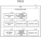
- the transfer to the encrypted tunnel is performed by the transfer unit 113 of the ingress KM (in Fig. 3A , KM 1-5) via the network IF unit 12.
- the transfer unit 113 receives the G key data subjected to the key relay from the KM 1-4 on the access QKDN 100-2 via the network IF unit 12.
- the decryption unit 115 decrypts the G key with the L key shared with the KM 1-4 on the access QKDN 100-2 from which the G key data is transferred.
- the transfer unit 113 refers to the routing path information to identify the transfer destination node as the egress KM (in Fig. 3A , KM 1-10).
- the encryption unit 114 encrypts the G key with the M key shared with the egress KM, and the transfer unit 113 transfers the G key encrypted with the M key to the egress KM via the network IF unit 12 (key relay using an encrypted tunnel with the M key).
- the transfer destination of the G key encrypted with the M key may be a virtual interface set in the egress KM at the time of establishing the M-key encrypted tunnel.
- the memory unit 14 may store the M key used to establish the M-key encrypted tunnel in a dedicated database (storage area) separately, or may store the M key similarly to the general G key.
- the reception from the encrypted tunnel is performed by the transfer unit 113 of the ingress KM (in Fig. 3A , KM 1-10) via the network IF unit 12.
- the transfer unit 113 receives the G key data encrypted with the M key from the ingress KM (in Fig. 3A , KM 1-5) via the network IF unit 12 by the virtual interface set at the time of establishing the M-key encrypted tunnel.
- the decryption unit 115 decrypts the G key data encrypted with the M key by using the M key shared with the ingress KM. Specifically, the decryption unit 115 identifies a transmission source KM from the transmission source of the IP packet including the decrypted G key data, and identifies a decryption key used for decrypting the data (IP packet). That is, the decryption unit 115 determines, according to the transmission source KM, whether to perform decryption with the M key or decryption with a normal L key other than decryption of the M-key encrypted tunnel communication.
- the M key shared with the ingress KM is stored in the memory unit 14 in association with, for example, the virtual interface encrypted with the M key and receiving the G key data or the transmission source KM (in Fig. 3A , KM 1-5). Further, for example, the normal L key is stored in the memory unit 14 in association with the transmission source KM.
- the transfer unit 113 refers to the routing path information to identify the KM 1 on the access QKDN 100-3 as the transfer destination KM, and the encryption unit 114 encrypts the G key data with the L key shared with the transfer destination KM. The transfer unit 113 then transfers the encrypted G key data to the transfer destination KM via the network IF unit 12.
- the transfer of the encrypted tunnel traffic is performed by the transfer unit 113 of the relay KM (in Figs. 2A and 3A , KM 1-6 and KM 1-9) via the network IF unit 12.
- the transfer unit 113 receives the IP packet of M-key encrypted tunnel traffic via the network IF unit 12. The transfer unit 113 determines whether the received IP packet is the M-key encrypted tunnel traffic. The transfer unit 113 performs different transfer processing depending on whether or not the received IP packet is the M-key encrypted tunnel traffic.
- Specific Exemplary Illustration 1 of the method of determining whether the received IP packet is the M-key encrypted tunnel traffic includes a method of determining whether the destination IP address of the received IP packet is addressed to the subject device. Specifically, whether the destination IP address is addressed to the subject device can be determined from the received IP packet as illustrated in Fig. 4 . If the destination of the received IP address is the subject device, then the decryption unit 115 decrypts the IP packet with the L key because the IP packet is not the IP packet of the M-key encrypted tunnel traffic.
- the decryption unit 115 transfers the IP packet as it is without decrypting or encrypting the IP packet because the IP packet is the IP packet of the M-key encrypted tunnel traffic.
- Specific Exemplary Illustration 2 of the method of determining whether the received IP packet is the M-key encrypted tunnel traffic includes a method of using a type of the destination IP address of the received IP packet.
- an IP address for transferring the M-key encrypted tunnel traffic that is, the IP address not to be encrypted/decrypted with the L key
- an IP address for performing normal key relay that is, the IP address to be encrypted/decrypted with the L key
- Specific Exemplary Illustration 3 of the method of determining whether the received IP packet is the M-key encrypted tunnel traffic includes a method of using a protocol number of data included in the received IP packet.
- the protocol number of the IP packet carrying the M-key encrypted tunnel traffic and the protocol number of the IP packet carrying the normal G key relay traffic are separately operated.
- the decryption unit 115 does not perform OTP decryption with the L key.
- the transfer unit 113 performs transfer processing of the M-key encrypted tunnel traffic. To be specific, the transfer unit 113 transfers the IP packet of the M-key encrypted tunnel traffic as a router when the IP packet is transmitted via the network IF unit 12. Further, when the IP packet of the M-key encrypted tunnel traffic is transferred via the network IF unit 12, the transfer unit 113 may set identification information (for example, a protocol number) indicating that the IP packet is the tunnel traffic in the IP packet.
- identification information for example, a protocol number
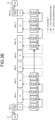
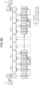
- Fig. 8 is a flowchart illustrating an operation example of the KM 1 according to the arrangement.
- the example of Fig. 8 illustrates an operation example for a case where the KM 1-10 in Fig. 3A operates as the relay KM, the ingress KM, or the egress KM.
- the transfer unit 113 receives received data (IP packet) from the transmission source KM 1 via the network IF unit 12 (Step Sl). Next, the transfer unit 113 determines whether or not the destination KM of the data received in Step S1 is the subject device (Step S2).
- Step S7 If the destination KM is not the subject device (Step S2, No), then the transfer unit 113 transfers, as the relay KM, the received data as it is via the network IF unit 12 (Step S7).
- the decryption unit 115 identifies a decryption key from the received data and decrypts the received data with the decryption key (Step S3). Specifically, the decryption unit 115 identifies a decryption key used for decryption by identifying the transmission source KM 1 from the transmission source address included in the received data.
- the M key shared with the KM 1-5 is identified as the decryption key used for decryption.
- the L key shared with the KM 1-8 is identified as the decryption key used for decryption.
- the L key shared with the KM 1-9 is identified as the decryption key used for decryption.
- the L key shared with the KM 1-11 is identified as the decryption key used for decryption.
- the transfer unit 113 refers to the IP packet transfer table to identify a next hop IP address of the received data (Step S4).
- the encryption unit 114 identifies an encryption key from the destination KM 1 corresponding to the next hop IP address, and encrypts the received data with the encryption key (Step S5).
- the M key shared with the KM 1-5 is identified as the encryption key used for encryption.
- the L key shared with the KM 1-8 is identified as the encryption key used for encryption.
- the L key shared with the KM 1-9 is identified as the encryption key used for encryption.
- the L key shared with the KM 1-11 is identified as the encryption key used for encryption.
- the transfer unit 113 transfers the received data encrypted in Step S5 to the destination KM 1 identified based on the next hop IP address via the network IF unit 12 (Step S6) .
- the processing unit 11 establishes M-key encrypted tunnel communication with the second node by using the M key (second encryption key) that is subjected to encrypted relay transmission to the second node that is one of the plurality of KMs 1 by the L key (first encryption key) shared, by quantum key distribution, with the plurality of KMs 1 (first nodes) adjacent to each other. Then, the processing unit 11 causes the network IF unit 12 to transfer the G key (third encryption key) to the second node by the M-key encrypted tunnel communication.
- the encrypted tunnel using the M key is preferably set between the KMs 1 having a higher communication frequency.
- the KMs 1 between which a communication frequency is high are, for example, KMs 1 (for example, in the example of Fig. 2A , the KM 1-5 and the KM 1-10) corresponding to the gateway of the QKDN 100.
- setting in advance an encrypted tunnel using an M key corresponds to concealment of the key relay method in the corresponding QKDN 100.
- setting the M-key encrypted tunnel in advance in the KM 1-5 and the KM 1-10 corresponds to hiding the backbone QKDN 100-1.
- the description similar to the arrangement is omitted, and portions different from the arrangement is described.
- the first modification a case where the M-key encrypted tunnel using the M key is established between the end KMs 1 with which the connected application 3 frequently communicates will be described.
- the KM 1-1 provides an encryption key (G key) to the application 3-1.
- the KM 1-12 provides an encryption key (G key) to the application 3-2.
- the KM 1-1 and the KM 1-12 can easily make the determination autonomously as to (a) "case where G key sharing is performed at a certain frequency or more in a specific route" in "3. Specific example of establishing encrypted tunnel" in the determination of encrypted tunnel establishment/stop described above. That is, the KM 1-1 and the KM 1-12 can autonomously perform determination of the M-key encrypted tunnel establishment/stop without receiving an instruction from an external QKDN manager.
- Fig. 10 is an overall view illustrating an example of the QKDN system 200-2 according to the first modification to the arrangement. As illustrated in Fig. 10 , the QKDN system 200-2 according to the first modification further includes a cryptographic communication network 101.
- the processing unit 11 of the KM 1-1 provides the connected application 3 (for example, the application 3-3) with the G key (third encryption key) shared via the encrypted tunnel with the M key, or the G key (third encryption key) shared by a normal key relay using the L key.
- the application 3-3 encrypts a communication message (plaintext) to the communication destination application 3-4 using the G key received from the KM 1-1, and transmits the encrypted message to the application 3-4 via the cryptographic communication network 101.
- the encryption method used by the application 3-3 may be OTP, advanced encryption standard (AES), or any encryption method.
- the cryptographic communication network 101 may be implemented on the same network as the QKDN 100 in which the KM 1 implements the key relay, or may be configured as another network.
- the description goes on to the second modification to the arrangement.
- the description similar to the arrangement is omitted, and portions different from the arrangement is described.
- the second modification a case is described in which the KM 1 further has a function of receiving plaintext data from the application 3, encrypting the plaintext data with the G key, and transmitting the ciphertext to the application 3 as a communication destination, and a function of decrypting the ciphertext.
- Fig. 11 is an overall view illustrating an example of a QKDN system 200-3 according to the second modification to the arrangement.
- the processing unit 11 of the KM 1-1 encrypts the plaintext data received from the application 3-3 with the G key, and transmits the ciphertext to the application 3-4 as a communication destination via the cryptographic communication network 101.
- the processing unit 11 of the KM 1-12 transmits, to the application 3-4, the plaintext obtained by decrypting the ciphertext received via the cryptographic communication network 101 with the G key shared with the KM 1-1.
- a management device 4 having a function of a network management manager that controls establishment and stop of M-key encrypted tunnel communication is provided on the cryptographic communication network 101.
- the control unit 111 of each KM 1 may control establishment of the M-key encrypted tunnel or stop of the M-key encrypted tunnel according to an instruction from the management device 4.
- the management device 4 receives an instruction to operate and stop the M-key encrypted tunnel communication, for example, from an administrator of the QKDN system 200-3.
- the management device 4 may be provided somewhere other than the cryptographic communication network 101. For example, the management device 4 may be provided on the QKDN 100.
- Fig. 12 is a diagram illustrating an example of a functional configuration of the KM 1 according to the arrangement.
- the KM 1 according to the second modification includes the processing unit 11, the network IF unit 12, the random number generating unit 13, and the memory unit 14.
- the processing unit 11 includes the control unit 111, the tunnel establishment processing unit 112, the transfer unit 113, a first encryption unit 114, a first decryption unit 115, a second encryption unit 116, and a second decryption unit 117. Since the control unit 111, the tunnel establishment processing unit 112, the first encryption unit 114, and the first decryption unit 115 are similar to the control unit 111, the tunnel establishment processing unit 112, the encryption unit 114, and the decryption unit 115 of the arrangement, the description thereof will be omitted.
- the second encryption unit 116 encrypts the plaintext data received from the application 3 with the G key (third encryption key) shared with the destination KM 1 to generate ciphertext.
- the second decryption unit 117 decrypts the ciphertext received via the cryptographic communication network 101 with the G key (third encryption key) shared with the transmission source KM 1 to generate plaintext data.
- the transfer unit 113 of the second modification further, via the network IF unit 12, receives the plaintext data from the application 3, transfers the ciphertext generated by the second encryption unit 116, receives the ciphertext transmitted from the transmission source KM 1, and transfers the plaintext data generated by the second decryption unit 117.
- the encryption method used for encrypting the plaintext data and decrypting the ciphertext may be OTP, AES, or any encryption method.
- the cryptographic communication network 101 may be implemented on the same network as the QKDN 100 in which the KM 1 implements the key relay, or may be configured as another network.
- Fig. 13 is a diagram illustrating an example of a hardware configuration of the QKD 2 according to the arrangement.
- the QKD 2 of the arrangement includes a control device 301, a main storage device 302, an auxiliary storage device 303, a display device 304, an input device 305, a quantum communication interface (IF) 306, and a classical communication IF 307.
- IF quantum communication interface
- the control device 301, the main storage device 302, the auxiliary storage device 303, the display device 304, the input device 305, the quantum communication IF 306, and the classical communication IF 307 are connected to one another via a bus 310.
- the control device 301 executes a program read from the auxiliary storage device 303 to the main storage device 302.
- the main storage device 302 is a memory such as a read only memory (ROM) and a RAM.
- the auxiliary storage device 303 is an HDD, a memory card, or the like.
- the display device 304 displays a state of the QKD 2 and the like.
- the input device 305 receives an input from a user.
- the display device 304 and the input device 305 may be implemented by a touch panel or the like having a display function and an input function.
- the display device 304 and the input device 305 do not have to be provided in the QKD 2. In this case, for example, a display function and an input function of an external terminal connected to the QKD 2 are used.
- the quantum communication IF 306 is an interface for connecting to a QKD link in which photons are transmitted.
- the classical communication IF 307 is an interface for connecting to a transmission path in which a control signal and the like are transmitted.
- Fig. 14 is a diagram illustrating an example of a hardware configuration of the KM 1 according to the arrangement.
- the KM 1 of the arrangement includes a control device 401, a main storage device 402, an auxiliary storage device 403, a display device 404, an input device 405, and a communication IF 406.
- the control device 401, the main storage device 402, the auxiliary storage device 403, the display device 404, the input device 405, and the communication IF 406 are connected to one another via a bus 410.
- the control device 401 executes a program read from the auxiliary storage device 403 to the main storage device 402.
- the main storage device 402 is a memory such as a ROM and a RAM.
- the auxiliary storage device 403 is an HDD, a memory card, or the like.
- the display device 404 displays a state of the KM 1 and the like.
- the input device 405 receives an input from a user.
- the display device 404 and the input device 405 may be implemented by a touch panel or the like having a display function and an input function.
- the display device 404 and the input device 405 do not have to be provided in the KM 1. In this case, for example, a display function and an input function of an external terminal connected to the KM 1 are used.
- the communication IF 406 is an interface for connecting to a transmission path.
- the hardware configuration of the management device 4 of the second modification is also similar to the hardware configuration of the KM 1 illustrated in Fig. 14 .
- a program to be executed by the KM 1 and the QKD 2 of the arrangement is stored as a file of a format that can be installed or executed and recorded on a computer-readable storage medium such as a CD-ROM, a memory card, a CD-R, or a digital versatile disk (DVD) and is provided as a computer program product.
- a computer-readable storage medium such as a CD-ROM, a memory card, a CD-R, or a digital versatile disk (DVD)
- the program executed by the KM 1 and the QKD 2 of the arrangement may be stored on a computer connected to a network such as the Internet, and provided after being downloaded via the network.
- the program executed by the KM 1 and the QKD 2 of the arrangement may be provided via a network such as the Internet without being downloaded.
- the program executed by the KM 1 and the QKD 2 of the arrangement may be installed on the ROM or the like in advance and provided.
- the program executed by the KM 1 of the arrangement has a module configuration including functions that can be implemented by the program among the functional configurations of the KM 1.
- the control device 401 reads the program from the storage medium such as the auxiliary storage device 403 and executes the program, whereby the function implemented by the program is loaded to the main storage device 402. That is, the function implemented by the program is generated on the main storage device 402.
- the IC is, for example, a processor that executes dedicated processing.
- each processor may achieve one of the functions or may achieve two or more of the functions.
- the operation forms of the KM 1 and the QKD 2 may be arbitrary.
- the KM 1 and the QKD 2 may be operated as, for example, the QKDN system 200 that achieves cryptographic communication of a cloud system on a network.
- an information processing device (1) includes a processing unit (11).
- the processing unit (11) is configured to establish encrypted tunnel communication with a second node by using a second encryption key subjected to encrypted relay transmission to the second node by a first encryption key shared, by quantum key distribution, with a plurality of first nodes adjacent to each other, where the second node is one of the plurality of first nodes.
- the processing unit (11) is configured to cause a network interface (IF) unit (12) to transfer a third encryption key to the second node by the encrypted tunnel communication.
- IF network interface
- Example 2 In the information processing device (1) according to example 1, the information processing device (1) is one of the plurality of first nodes, and the processing unit (11) is configured to perform encrypted relay transmission of the second encryption key to a first node adjacent to the information processing device (1) by using a first encryption key shared with the first node adjacent to the information processing device (1).
- Example 3 In the information processing device (1) according to example 1 or 2, the information processing device (1) is configured to communicate with at least one application, and the processing unit (11) is configured to provide the third encryption key to the application.
- Example 4 In the information processing device (1) according to example 1 or 2, the information processing device (1) is configured to communicate with at least one first application.
- the processing unit (11) is configured to generate encrypted data by encrypting plaintext data received from the first application with the third encryption key, and cause the network IF unit (12) to transfer the encrypted data to the second node.
- Example 5 In the information processing device (1) according to any one of examples 1 to 4, the processing unit (11) is configured to encapsulate a first communication packet including data obtained by encrypting the third encryption key with the second encryption key, in a second communication packet whose source is an address of the information processing device (1) and whose destination is an address of the second node, and cause the network IF unit (12) to transfer the second communication packet to the second node.
- Example 6 In the information processing device (1) according to any one of examples 1 to 5, the processing unit (11) is configured to request the second node to establish the encrypted tunnel communication, and establish encrypted tunnel communication with the second node according to a response from the second node.
- Example 7 In the information processing device (1) according to any one of examples 1 to 6, when receiving a request for establishing the encrypted tunnel communication from the second node and sending back a response indicating approval to the second node, the processing unit (11) is configured to establish encrypted tunnel communication with the second node.
- Example 8 The information processing device (1) according to any one of examples 1 to 7, further includes a memory unit (14) configured to store the first encryption key, the second encryption key, and the third encryption key therein.
- the processing unit (11) is configured to establish the encrypted tunnel communication in a case where a storage amount of the second encryption key shared with the second node is larger than a first amount, and stop the encrypted tunnel communication in a case where the storage amount is smaller than a second amount.
- Example 9 In the information processing device (1) according to any one of examples 1 to 8, the processing unit (11) is configured to control establishment and stop of encrypted tunnel communication with the second node according to an instruction from a management device configured to control establishment and stop of the encrypted tunnel communication.
- Example 10 In the information processing device (1) according to any one of examples 1 to 9, the processing unit (11) is configured to establish the encrypted tunnel communication in a case where a request amount per unit time of the third encryption key shared with the second node is larger than a first amount, and stop the encrypted tunnel communication in a case where the request amount is smaller than a second amount.
- a quantum key distribution (QKD) network system includes a plurality of first nodes, a plurality of QKD devices, a first application, and a second application.
- the plurality of first nodes includes the information processing device (1) according to example 1 or 2 and the second node.
- the plurality of QKD devices is configured to generate the first encryption key by quantum key distribution, and provide the generated first encryption key to any of the plurality of first nodes.
- the first application is configured to receive the third encryption key from the information processing device (1) according to example 1 or 2.
- the second application is configured to receive the third encryption key from the second node.
- a computer program product has a computer readable medium including programmed instructions stored thereon.
- the instructions When executed by a computer, the instructions cause the computer to establish encrypted tunnel communication with a second node by using a second encryption key subjected to encrypted relay transmission to the second node by a first encryption key shared, by quantum key distribution, with a plurality of first nodes adjacent to each other where the second node is one of the plurality of first nodes; and transfer a third encryption key to the second node by the encrypted tunnel communication.
Landscapes
- Engineering & Computer Science (AREA)
- Computer Security & Cryptography (AREA)
- Computer Networks & Wireless Communication (AREA)
- Signal Processing (AREA)
- Physics & Mathematics (AREA)
- Electromagnetism (AREA)
- Theoretical Computer Science (AREA)
- Data Exchanges In Wide-Area Networks (AREA)
Applications Claiming Priority (1)
| Application Number | Priority Date | Filing Date | Title |
|---|---|---|---|
| JP2023150672A JP7826256B2 (ja) | 2023-09-19 | 2023-09-19 | 情報処理装置、qkdネットワークシステム、情報処理方法及びプログラム |
Publications (1)
| Publication Number | Publication Date |
|---|---|
| EP4529079A1 true EP4529079A1 (fr) | 2025-03-26 |
Family
ID=91853686
Family Applications (1)
| Application Number | Title | Priority Date | Filing Date |
|---|---|---|---|
| EP24186677.1A Pending EP4529079A1 (fr) | 2023-09-19 | 2024-07-04 | Dispositif de traitement d'informations, système de réseau qkd, procédé de traitement d'informations et produit de programme informatique |
Country Status (3)
| Country | Link |
|---|---|
| US (1) | US20250097031A1 (fr) |
| EP (1) | EP4529079A1 (fr) |
| JP (1) | JP7826256B2 (fr) |
Citations (1)
| Publication number | Priority date | Publication date | Assignee | Title |
|---|---|---|---|---|
| CN110581763A (zh) * | 2018-06-09 | 2019-12-17 | 成都零光量子科技有限公司 | 一种量子密钥服务区块链网络系统 |
Family Cites Families (10)
| Publication number | Priority date | Publication date | Assignee | Title |
|---|---|---|---|---|
| JP2004140482A (ja) * | 2002-10-16 | 2004-05-13 | Fujitsu Ltd | 暗号通信を行うノード装置、暗号通信システムおよび方法 |
| JP2009010606A (ja) * | 2007-06-27 | 2009-01-15 | Panasonic Corp | トンネル接続システム、トンネル管理サーバ、トンネル接続装置、及びトンネル接続方法 |
| GB0822253D0 (en) * | 2008-12-05 | 2009-01-14 | Qinetiq Ltd | Method of establishing a quantum key for use between network nodes |
| JP5672425B2 (ja) * | 2009-10-07 | 2015-02-18 | 日本電気株式会社 | 暗号通信システムおよび暗号通信方法 |
| JP6478749B2 (ja) * | 2015-03-24 | 2019-03-06 | 株式会社東芝 | 量子鍵配送装置、量子鍵配送システムおよび量子鍵配送方法 |
| US11469888B2 (en) * | 2019-05-03 | 2022-10-11 | Quantumxchange, Inc. | Tamper detection in a quantum communications system |
| CN113765664B (zh) * | 2021-11-10 | 2022-02-08 | 济南量子技术研究院 | 基于量子密钥的区块链网络安全通信方法 |
| JP7669309B2 (ja) * | 2022-03-15 | 2025-04-28 | 株式会社東芝 | 量子暗号通信システム、鍵管理装置及び鍵管理方法 |
| US20240291640A1 (en) * | 2023-02-27 | 2024-08-29 | Jpmorgan Chase Bank, N.A. | Systems and methods for quantum key distribution secured vault-based application-to-application communication |
| US12452046B2 (en) * | 2023-04-21 | 2025-10-21 | Jpmorgan Chase Bank, N.A. | Systems and methods for secure cryptographic secret distribution |
-
2023
- 2023-09-19 JP JP2023150672A patent/JP7826256B2/ja active Active
-
2024
- 2024-07-03 US US18/763,052 patent/US20250097031A1/en active Pending
- 2024-07-04 EP EP24186677.1A patent/EP4529079A1/fr active Pending
Patent Citations (1)
| Publication number | Priority date | Publication date | Assignee | Title |
|---|---|---|---|---|
| CN110581763A (zh) * | 2018-06-09 | 2019-12-17 | 成都零光量子科技有限公司 | 一种量子密钥服务区块链网络系统 |
Non-Patent Citations (2)
| Title |
|---|
| PENG ZHOU ET AL: "Performance Evaluation and Optimization Method in QKD Network for Digital Power Grid", 2022 IEEE 5TH ADVANCED INFORMATION MANAGEMENT, COMMUNICATES, ELECTRONIC AND AUTOMATION CONTROL CONFERENCE (IMCEC), IEEE, vol. 5, 16 December 2022 (2022-12-16), pages 822 - 825, XP034281936, DOI: 10.1109/IMCEC55388.2022.10019907 * |
| TAKAHASHI RIRIKA ET AL: "A high-speed key management method for quantum key distribution network", 2019 ELEVENTH INTERNATIONAL CONFERENCE ON UBIQUITOUS AND FUTURE NETWORKS (ICUFN), IEEE, 2 July 2019 (2019-07-02), pages 437 - 442, XP033600768, DOI: 10.1109/ICUFN.2019.8806052 * |
Also Published As
| Publication number | Publication date |
|---|---|
| JP7826256B2 (ja) | 2026-03-09 |
| JP2025043426A (ja) | 2025-04-01 |
| US20250097031A1 (en) | 2025-03-20 |
Similar Documents
| Publication | Publication Date | Title |
|---|---|---|
| CN1756234B (zh) | 服务器、vpn客户装置、vpn系统 | |
| JP6478749B2 (ja) | 量子鍵配送装置、量子鍵配送システムおよび量子鍵配送方法 | |
| EP3996325B1 (fr) | Dispositif de transfert, dispositif de serveur de gestion de clé, système de communication, procédé de transfert et support lisible sur ordinateur | |
| EP3996324B1 (fr) | Dispositif de transfert, dispositif de serveur de gestion de clé, système de communication, procédé de transfert, et support lisible sur ordinateur | |
| US7869446B2 (en) | Optimized dynamic multipoint virtual private network over IPv6 network | |
| EP4038824B1 (fr) | Réutilisation d'association de sécurité pour connexions multiples | |
| CN111371798A (zh) | 数据安全传输方法、系统、装置及存储介质 | |
| US9509589B2 (en) | Communication device, communication system, communication method, and computer program product | |
| JP7793711B2 (ja) | 通信装置、通信方法、通信システムおよびプログラム | |
| EP4346255B1 (fr) | Communications chiffrées par satellite | |
| EP3944555B1 (fr) | Système de communication, dispositif de serveur de gestion de clé, routeur, et support lisible sur ordinateur | |
| CN105471827A (zh) | 一种报文传输方法及装置 | |
| CN106209401B (zh) | 一种传输方法及装置 | |
| EP4529079A1 (fr) | Dispositif de traitement d'informations, système de réseau qkd, procédé de traitement d'informations et produit de programme informatique | |
| JP2005244379A (ja) | Vpnシステム、vpn装置及びそれらに用いる暗号化鍵配布方法 | |
| US12244493B2 (en) | Securing multiprotocol label switching (MPLS) payloads | |
| CN116016529A (zh) | IPSec VPN设备负载均衡管理方法和装置 | |
| KR101837064B1 (ko) | 보안 통신 장치 및 방법 | |
| EP4618471A1 (fr) | Dispositif de traitement d'informations, système de communication cryptographique quantique, procédé de traitement d'informations et support lisible par ordinateur | |
| EP4607378A1 (fr) | Dispositif de traitement d'informations, système de communication cryptographique quantique, procédé de traitement d'informations et support lisible par ordinateur | |
| CN120074898B (zh) | 通信方法及装置 | |
| CN119449438A (zh) | 一种传输模式全域量子安全加密设备及数据处理方法 | |
| CN119544580A (zh) | 通信方法及装置 |
Legal Events
| Date | Code | Title | Description |
|---|---|---|---|
| PUAI | Public reference made under article 153(3) epc to a published international application that has entered the european phase |
Free format text: ORIGINAL CODE: 0009012 |
|
| STAA | Information on the status of an ep patent application or granted ep patent |
Free format text: STATUS: REQUEST FOR EXAMINATION WAS MADE |
|
| 17P | Request for examination filed |
Effective date: 20240704 |
|
| AK | Designated contracting states |
Kind code of ref document: A1 Designated state(s): AL AT BE BG CH CY CZ DE DK EE ES FI FR GB GR HR HU IE IS IT LI LT LU LV MC ME MK MT NL NO PL PT RO RS SE SI SK SM TR |