EP4529101A1 - Procédé de communication et appareil de communication - Google Patents
Procédé de communication et appareil de communication Download PDFInfo
- Publication number
- EP4529101A1 EP4529101A1 EP23815219.3A EP23815219A EP4529101A1 EP 4529101 A1 EP4529101 A1 EP 4529101A1 EP 23815219 A EP23815219 A EP 23815219A EP 4529101 A1 EP4529101 A1 EP 4529101A1
- Authority
- EP
- European Patent Office
- Prior art keywords
- path parameter
- parameter group
- search range
- information
- range information
- Prior art date
- Legal status (The legal status is an assumption and is not a legal conclusion. Google has not performed a legal analysis and makes no representation as to the accuracy of the status listed.)
- Pending
Links
Images




Classifications
-
- H—ELECTRICITY
- H04—ELECTRIC COMMUNICATION TECHNIQUE
- H04L—TRANSMISSION OF DIGITAL INFORMATION, e.g. TELEGRAPHIC COMMUNICATION
- H04L25/00—Baseband systems
- H04L25/02—Details ; arrangements for supplying electrical power along data transmission lines
- H04L25/0202—Channel estimation
-
- H—ELECTRICITY
- H04—ELECTRIC COMMUNICATION TECHNIQUE
- H04L—TRANSMISSION OF DIGITAL INFORMATION, e.g. TELEGRAPHIC COMMUNICATION
- H04L25/00—Baseband systems
- H04L25/02—Details ; arrangements for supplying electrical power along data transmission lines
- H04L25/0202—Channel estimation
- H04L25/0224—Channel estimation using sounding signals
-
- H—ELECTRICITY
- H04—ELECTRIC COMMUNICATION TECHNIQUE
- H04B—TRANSMISSION
- H04B7/00—Radio transmission systems, i.e. using radiation field
- H04B7/02—Diversity systems; Multi-antenna system, i.e. transmission or reception using multiple antennas
- H04B7/04—Diversity systems; Multi-antenna system, i.e. transmission or reception using multiple antennas using two or more spaced independent antennas
- H04B7/06—Diversity systems; Multi-antenna system, i.e. transmission or reception using multiple antennas using two or more spaced independent antennas at the transmitting station
- H04B7/0613—Diversity systems; Multi-antenna system, i.e. transmission or reception using multiple antennas using two or more spaced independent antennas at the transmitting station using simultaneous transmission
- H04B7/0615—Diversity systems; Multi-antenna system, i.e. transmission or reception using multiple antennas using two or more spaced independent antennas at the transmitting station using simultaneous transmission of weighted versions of same signal
- H04B7/0619—Diversity systems; Multi-antenna system, i.e. transmission or reception using multiple antennas using two or more spaced independent antennas at the transmitting station using simultaneous transmission of weighted versions of same signal using feedback from receiving side
- H04B7/0636—Feedback format
- H04B7/0641—Differential feedback
-
- H—ELECTRICITY
- H04—ELECTRIC COMMUNICATION TECHNIQUE
- H04B—TRANSMISSION
- H04B7/00—Radio transmission systems, i.e. using radiation field
- H04B7/02—Diversity systems; Multi-antenna system, i.e. transmission or reception using multiple antennas
- H04B7/04—Diversity systems; Multi-antenna system, i.e. transmission or reception using multiple antennas using two or more spaced independent antennas
- H04B7/06—Diversity systems; Multi-antenna system, i.e. transmission or reception using multiple antennas using two or more spaced independent antennas at the transmitting station
- H04B7/0613—Diversity systems; Multi-antenna system, i.e. transmission or reception using multiple antennas using two or more spaced independent antennas at the transmitting station using simultaneous transmission
- H04B7/0615—Diversity systems; Multi-antenna system, i.e. transmission or reception using multiple antennas using two or more spaced independent antennas at the transmitting station using simultaneous transmission of weighted versions of same signal
- H04B7/0619—Diversity systems; Multi-antenna system, i.e. transmission or reception using multiple antennas using two or more spaced independent antennas at the transmitting station using simultaneous transmission of weighted versions of same signal using feedback from receiving side
- H04B7/0658—Feedback reduction
-
- H—ELECTRICITY
- H04—ELECTRIC COMMUNICATION TECHNIQUE
- H04L—TRANSMISSION OF DIGITAL INFORMATION, e.g. TELEGRAPHIC COMMUNICATION
- H04L25/00—Baseband systems
- H04L25/02—Details ; arrangements for supplying electrical power along data transmission lines
- H04L25/0202—Channel estimation
- H04L25/0204—Channel estimation of multiple channels
-
- H—ELECTRICITY
- H04—ELECTRIC COMMUNICATION TECHNIQUE
- H04L—TRANSMISSION OF DIGITAL INFORMATION, e.g. TELEGRAPHIC COMMUNICATION
- H04L25/00—Baseband systems
- H04L25/02—Details ; arrangements for supplying electrical power along data transmission lines
- H04L25/0202—Channel estimation
- H04L25/022—Channel estimation of frequency response
Definitions
- This application relates to the field of communication technologies, and in particular, to a communication method and a communication apparatus.
- channel estimation After being transmitted by a transmit end, data arrives at a receive end through propagation of a radio channel. Various interference factors in the radio channel affect the transmitted data. Therefore, data received by the receive end may be greatly different from the data transmitted by the transmit end. Therefore, to mitigate impact of a propagation environment on data sending, channel estimation usually needs to be performed by using a pilot signal, and the data received by the receive end is further demodulated based on the channel estimation. Specifically, it is proposed in a conventional technology that a pilot signal known to the receive end may be transmitted while the data is transmitted. The receive end performs channel estimation based on a received pilot signal and the known pilot signal, and further demodulates the received data based on the channel estimation. However, this pilot signal sending manner increases pilot overheads.
- This application provides a communication method and a communication apparatus, to reduce pilot overheads.
- this application provides a communication method.
- the method is applied to a first device, and the method includes: determining path parameter group search range information and first information, where the first information indicates K path parameter groups, and K is an integer greater than 0; and sending the path parameter group search range information and the first information to a second device, where the path parameter group search range information is used to correct the K path parameter groups, and K corrected path parameter groups are used for channel estimation.
- the first device sends, to the second device, the first information indicating the K path parameter groups for channel estimation.
- this can reduce pilot overheads.
- the first terminal may further send the path parameter group search range information to the second device, where the path parameter group search range information is used to correct the K path parameter groups. Therefore, in comparison with an implementation in which the path parameter group search range information is not limited, based on the solution in this application, a calculation amount of correcting the K path parameter groups by the second device can be reduced, and this helps improve path parameter correction efficiency, that is, help improve calculation efficiency.
- the first information includes the K path parameter groups.
- the first device directly sends the K path parameter groups to the second device. This is intuitive, easy to operate, and has high applicability.
- the first information includes W reference path parameter groups corresponding to W types of path parameter groups and difference information corresponding to each reference path parameter group, and W is a positive integer less than K.
- W is a positive integer less than K.
- One type of path parameter group corresponds to one reference path parameter group, and the W types of path parameter groups are obtained by classifying the K path parameter groups.
- the K path parameter groups are indicated by using the reference path parameter group and the difference information. This helps reduce feedback overheads of the K path parameter groups.
- a first-type path parameter group corresponds to a first reference path parameter group
- the first-type path parameter group includes at least one path parameter group
- the first-type path parameter group is any one of the W types of path parameter groups
- the first reference path parameter group is determined based on the at least one path parameter group.
- a reference path parameter group may be determined based on path parameter groups included in a type of path parameter group associated with the reference path parameter group. Therefore, in comparison with directly feeding back the K path parameter groups, the reference path parameter group is sent to determine other K path parameter groups, to reduce feedback overheads of the path parameter group.
- the first reference path parameter group is one of the at least one path parameter group, or the first reference path parameter group is a path parameter group mean of the at least one path parameter group.
- a reference path parameter group may be a mean of a type of path parameter group associated with the reference path parameter group, or a reference path parameter group may be a path parameter group selected from a type of path parameter group, for example, may be a path parameter group that is closest to a centroid (that is, close to a mean) and that is selected from a type of path parameter group. Therefore, in comparison with directly feeding back the K path parameter groups, the reference path parameter group is sent to determine the other K path parameter groups, to reduce the feedback overheads of the path parameter group.
- one path parameter group may include the delay ⁇ and the attenuation A.
- one path parameter group may include the delay ⁇ , the attenuation A, the azimuth of arrival AOA, and the zenith of arrival ZOA.
- one path parameter group may include the delay ⁇ , the attenuation A, the azimuth of departure AOD, and the zenith of departure ZOD.
- one path parameter group may include the delay ⁇ , the attenuation A, the azimuth of arrival AOA, the zenith of arrival ZOA, the azimuth of departure AOD, and the zenith of departure ZOD.
- the multiple-input multiple-output scenario is used as an example.
- one path parameter group may include the delay search range information, the attenuation search range information, the azimuth of arrival search range information, the zenith of arrival search range information, the azimuth of departure search range information, and the zenith of departure search range information.
- this application provides a communication method.
- the method is applied to a second device, and the method includes: receiving first information from a first device, where the first information indicates K path parameter groups, and K is an integer greater than 0; and correcting the K path parameter groups based on path parameter group search range information, and performing channel estimation based on K corrected path parameter groups.
- the path parameter group search range information may be configured by the first device for the second device, may be obtained by the second device through calculation based on the K path parameter groups, or may be predefined in the protocol.
- a calculation amount of subsequently correcting the K path parameter groups by the second device can be reduced. This helps improve path parameter correction efficiency, that is, helps improve calculation efficiency.
- the first information includes the K path parameter groups.
- the first reference path parameter group is one of the at least one path parameter group, or the first reference path parameter group is a path parameter group mean of the at least one path parameter group.
- a transmission periodicity of the K path parameter groups is T1
- a transmission periodicity of the path parameter group search range information is T2, where T1 is different from T2.
- a transmission periodicity of the W reference path parameter groups is T0
- a transmission periodicity of the path parameter group search range information is T2
- a transmission periodicity of the difference information is T3, where T0 is greater than T3, and T2 is greater than T3.
- one path parameter group includes at least one of the following parameters: a delay ⁇ , attenuation A, an azimuth of arrival AOA, a zenith of arrival ZOA, an azimuth of departure AOD, and a zenith of departure ZOD.
- the path parameter group search range information includes at least one of the following information: delay search range information, attenuation search range information, azimuth of arrival search range information, zenith of arrival search range information, azimuth of departure search range information, and zenith of departure search range information.
- the apparatus includes: a processing unit, configured to determine path parameter group search range information and first information, where the first information indicates K path parameter groups, and K is an integer greater than 0; and a transceiver unit, configured to send the path parameter group search range information and the first information to a second device, where the path parameter group search range information is used to correct the K path parameter groups, and K corrected path parameter groups are used for channel estimation.
- the first information includes the K path parameter groups.
- the first information includes W reference path parameter groups corresponding to W types of path parameter groups and difference information corresponding to each reference path parameter group, and W is a positive integer less than K.
- W is a positive integer less than K.
- One type of path parameter group corresponds to one reference path parameter group, and the W types of path parameter groups are obtained by classifying the K path parameter groups.
- a first-type path parameter group corresponds to a first reference path parameter group
- the first-type path parameter group includes at least one path parameter group
- the first-type path parameter group is any one of the W types of path parameter groups
- the first reference path parameter group is determined based on the at least one path parameter group.
- the first reference path parameter group is one of the at least one path parameter group, or the first reference path parameter group is a path parameter group mean of the at least one path parameter group.
- a transmission periodicity of the K path parameter groups is T1
- a transmission periodicity of the path parameter group search range information is T2, where T1 is different from T2.
- a transmission periodicity of the W reference path parameter groups is T0
- a transmission periodicity of the path parameter group search range information is T2
- a transmission periodicity of the difference information is T3, where T0 is greater than T3, and T2 is greater than T3.
- one path parameter group includes at least one of the following parameters: a delay ⁇ , attenuation A, an azimuth of arrival AOA, a zenith of arrival ZOA, an azimuth of departure AOD, and a zenith of departure ZOD.
- the path parameter group search range information includes at least one of the following information: delay search range information, attenuation search range information, azimuth of arrival search range information, zenith of arrival search range information, azimuth of departure search range information, and zenith of departure search range information.
- an embodiment of this application further provides a communication apparatus.
- the communication apparatus may be used in the second device in the second aspect.
- the communication apparatus may be the second device, may be an apparatus (for example, a chip, a chip system, or a circuit) in the second device, or may be an apparatus that can be used together with the second device.
- the communication apparatus may include modules or units that are in one-to-one correspondence with the method/operations/steps/actions described in the first aspect.
- the modules or units may be hardware circuits, may be software, or may be implemented by hardware circuits in combination with software.
- the apparatus includes:
- the path parameter group search range information is configured by the first device
- the first information includes the K path parameter groups.
- the first information includes W reference path parameter groups corresponding to W types of path parameter groups and difference information corresponding to each reference path parameter group, and W is a positive integer less than K.
- W is a positive integer less than K.
- One type of path parameter group corresponds to one reference path parameter group, and the W types of path parameter groups are obtained by classifying the K path parameter groups.
- a first-type path parameter group corresponds to a first reference path parameter group
- the first-type path parameter group includes at least one path parameter group
- the first-type path parameter group is any one of the W types of path parameter groups
- the first reference path parameter group is determined based on the at least one path parameter group.
- the first reference path parameter group is one of the at least one path parameter group, or the first reference path parameter group is a path parameter group mean of the at least one path parameter group.
- a transmission periodicity of the K path parameter groups is T1
- a transmission periodicity of the path parameter group search range information is T2, where T1 is different from T2.
- one path parameter group includes at least one of the following parameters: a delay ⁇ , attenuation A, an azimuth of arrival AOA, a zenith of arrival ZOA, an azimuth of departure AOD, and a zenith of departure ZOD.
- the path parameter group search range information includes at least one of the following information: delay search range information, attenuation search range information, azimuth of arrival search range information, zenith of arrival search range information, azimuth of departure search range information, and zenith of departure search range information.
- this application provides a communication apparatus.
- the communication apparatus includes a processor, and the processor is configured to implement the method according to any one of the first aspect by using a logic circuit or by executing instructions.
- the apparatus further includes a transceiver, configured to send and receive a signal.
- the processor is coupled to a memory, and the memory stores the foregoing instructions.
- the apparatus further includes a memory, configured to store the foregoing instructions.
- the memory and the processor are integrated together.
- the memory and the processor are disposed separately.
- this application provides a communication apparatus.
- the communication apparatus includes a processor, and the processor is configured to implement the method according to any one of the second aspect by using a logic circuit or by executing instructions.
- the apparatus further includes a transceiver, configured to send and receive a signal.
- the processor is coupled to a memory, and the memory stores the foregoing instructions.
- the apparatus further includes a memory, configured to store the foregoing instructions.
- the memory and the processor are integrated together.
- the memory and the processor are disposed separately.
- this application provides a computer-readable storage medium.
- the storage medium stores a computer program or instructions, and when the computer program or the instructions are executed by a computer, the method according to any one of the first aspect and the second aspect is implemented.
- this application provides a computer program product including instructions.
- the computer program product includes a computer program or instructions, and when the computer program or the instructions are run on a computer, the method according to any one of the first aspect and the second aspect is implemented.
- a communication system includes the first device according to the third aspect and the second device according to the fourth aspect.
- A/B may represent A or B.
- a term “and/or” in this specification describes only an association relationship between associated objects and indicates that there may be three relationships.
- a and/or B may indicate the following three cases: Only A exists, both A and B exist, and only B exists.
- at least one means one or more, and "a plurality of” means two or more. Terms such as “first” and “second” do not limit a quantity and an execution sequence, and the terms such as “first” and “second” do not indicate a definite difference.
- LTE long term evolution
- FDD frequency division duplex
- TDD time division duplex
- 5G 5 th generation
- NR new radio
- 6G 6 th generation
- WLAN wireless Local Area Network
- FIG. 1 is a diagram of a structure a communication system according to an embodiment of this application.
- an access network device and a terminal device 1 to a terminal device 6 form a communication system.
- the terminal device 1 to the terminal device 6 may send uplink information to the access network device, and the access network device may also send downlink information to the terminal device 1 to the terminal device 6.
- the terminal device 4 to the terminal device 6 may also form a communication system.
- the access network device may send the downlink information to the terminal device 1, the terminal device 2, the terminal device 5, and the like.
- the terminal device 5 may also send the downlink information to the terminal device 4 and the terminal device 6.
- the terminal device 4 and the terminal device 6 may also send the uplink information to the access network device by using the terminal device 5.
- the terminal device in embodiments of this application may be a device having a wireless transceiver function, and may be specifically user equipment (user equipment, UE), an access terminal, a subscriber unit (subscriber unit), a subscriber station, a mobile station (mobile station), a customer-premises equipment (customer-premises equipment, CPE), a remote station, a remote terminal, a mobile device, a user terminal, a wireless communication device, a user agent, or a user apparatus.
- user equipment user equipment
- UE user equipment
- subscriber station a subscriber station
- mobile station mobile station
- customer-premises equipment customer-premises equipment
- CPE customer-premises equipment
- the terminal device may alternatively be a satellite phone, a cellular phone, a smartphone, a wireless data card, a wireless modem, a machine type communication device, a cordless phone, a session initiation protocol (session initiation protocol, SIP) phone, a wireless local loop (wireless local loop, WLL) station, a personal digital assistant (personal digital assistant, PDA), a handheld device having a wireless communication function, a computing device or another processing device connected to the wireless modem, a vehicle-mounted device, a communication device carried on high-altitude aircraft, a wearable device, an unmanned aerial vehicle, a robot, a smart point of sale (point of sale, POS) machine, a terminal in device-to-device (device-to-device, D2D) communication, a terminal in vehicle to everything (vehicle to everything, V2X), a virtual reality (virtual reality, VR) terminal device, an augmented reality (augmented reality, AR) terminal device, a wireless terminal in industrial control (industrial control),
- an apparatus configured to implement a function of the terminal device may be a terminal device, or may be an apparatus, for example, a chip system, that can support the terminal device in implementing the function.
- the apparatus may be mounted in the terminal device or used together with the terminal device.
- the chip system may include a chip, or may include a chip and another discrete component.
- the access network device in embodiments of this application may be a device having a wireless transceiver function, and is configured to communicate with the terminal device, or may be a device that connects the terminal device to a wireless network.
- the network device may be a node in a radio access network, and may also be referred to as a base station, or may be referred to as a radio access network (radio access network, RAN) node (or device).
- RAN radio access network
- the network device may be an evolved NodeB (evolved NodeB, eNB or eNodeB) in LTE, a next generation NodeB (next generation NodeB, gNB) in a 5G network or a base station in a future evolved public land mobile network (public land mobile network, PLMN), a broadband network gateway (broadband network gateway, BNG), an aggregation switch or a non-3 rd generation partnership project (3 rd generation partnership project, 3GPP) access device, or the like.
- eNodeB evolved NodeB
- gNB next generation NodeB
- 5G network Fifth Generation NodeB
- PLMN public land mobile network
- BNG broadband network gateway
- BNG broadband network gateway
- 3GPP non-3 rd generation partnership project
- the network device in embodiments of this application may include base stations in various forms, for example, a macro base station, a micro base station (also referred to as a small cell), a relay station, an access point, a device for implementing a base station function in a communication system evolved after 5G, an access point (access point, AP) in a Wi-Fi system, a transmission reception point (transmission reception point, TRP), a transmitting point (transmitting point, TP), a mobile switching center, and a device that undertakes a base station function in device-to-device (Device-to-Device, D2D), vehicle-to-everything (vehicle-to-everything, V2X), and machine-to-machine (machine-to-machine, M2M) communication, and may further include a central unit (central unit, CU) and a distributed unit (distributed unit, DU) in a cloud radio access network (cloud radio access network, C-RAN) system,
- the access network device may communicate and interact with a core network device, to provide a communication service for the terminal device.
- the core network device is, for example, a device in a 5G network core network (core network, CN).
- core network CN
- the core network provides an interface to a data network, provides communication connection, authentication, management, and policy control for a terminal, and bearers a data service.
- an apparatus configured to implement a function of the network device may be a network device, or may be an apparatus, for example, a chip system, that can support the network device in implementing the function.
- the apparatus may be mounted in the network device or used together with the network device.
- the first device in embodiments of this application may be an access network device, and the second device may be a terminal device.
- the first device in this application may be a terminal device, and the second device may be an access network device.
- this application is applicable to a downlink scenario or an uplink scenario.
- the following embodiments of this application are mainly described by using the downlink scenario as an example. That is, the first device is an access network device, and the second device is a terminal device.
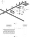
- FIG. 2 is a diagram of an application scenario according to an embodiment of this application.
- a first device is a network device
- a second device is a terminal device.
- the network device transmits a signal
- the transmitted signal may arrive at the terminal device through a line of sight (line of sight, LOS) path (path) (a LOS path shown in FIG. 2 ) and a non-line of sight (Non-Line Of Sight, NLOS) path (an NLOS path 1 and an NLOS path 2 shown in FIG. 2 ), and the terminal device demodulates a received signal.
- line of sight line of sight
- path path
- NLOS Non-Line Of Sight
- channel estimation usually needs to be performed by using a pilot signal, and the data received by the receive end is further demodulated based on the channel estimation.
- a pilot signal known to the receive end may be transmitted while the data is transmitted. The receive end performs channel estimation based on a received pilot signal and the known pilot signal, and further demodulates the received data based on the channel estimation.
- a pilot for example, a demodulation reference signal (demodulation reference signal, DMRS) used for demodulating data is sent together with the data.
- the pilot is used to estimate a channel, and then demodulate the data based on information about the estimated channel.
- DMRS demodulation reference signal
- a channel response is obtained completely by using the pilot.
- this pilot signal sending manner increases pilot overheads.
- embodiments of this application further provide a solution in which the wireless sensing technology may be combined with channel estimation to assist in the channel estimation, so that pilot overheads can be reduced.
- four-dimension (four-dimension, 4D) information (where the 4D information includes three-dimension (three-dimension, 3D) environment information and electromagnetic information of a 3D environment) of a surrounding propagation environment and location information of a transmit end (TX) and a receive end (RX) may be obtained by using the wireless sensing technology.
- a path parameter group is determined based on the 4D information and the location information of the TX and the RX, and channel estimation is performed based on the path parameter group, to reduce the communication pilot overheads.
- the 4D environment information and location information of a transceiver may be obtained.
- a path parameter corresponding to a channel may be calculated based on the 4D environment information and a location of the transceiver. Because errors inevitably exist in the location of the transceiver and an environment parameter, the calculated path parameter is inaccurate.
- the path parameter needs to be corrected by using a small quantity of pilots, and channel reconstruction is further performed based on a corrected path parameter.
- “the small quantity of pilots+the path parameter ⁇ the corrected path parameter ⁇ a channel response” is used. In comparison with the manner in which the channel response is obtained completely by using the pilot in the conventional technology, pilot overheads used in this application are reduced.
- this application provides a communication method and a communication apparatus, to reduce the pilot overheads.
- FIG. 3 is an interaction diagram of a communication method according to an embodiment of this application. As shown in FIG. 3 , the communication method includes the following steps S301 and S302.
- a first device sends first information to a second device, and correspondingly the second device receives the first information from the first device.
- the first information indicates K path parameter groups, and K is an integer greater than 0. It may be understood that the K path parameter groups in this embodiment of this application may be understood as path parameter groups corresponding to K communication paths, and one communication path corresponds to one path parameter group.
- the first device determines the first information, and sends the first information to the second device.
- the second device receives the first information from the first device.
- the first device determines the first information may be understood as that the first device receives the first information from a third device.
- the third device may be another device with a strong calculating capability.
- that the first device determines the first information may alternatively be understood as that the first device obtains location information of the first device, location information of the second device, and 4D environment information, and determines the K path parameter groups based on the location information of the first device, the location information of the second device, and the 4D environment information.
- the 4D environment information includes 3D environment information and electromagnetic information of the 3D environment information.
- a calculation algorithm may be a full-wave electromagnetic calculation method, a ray tracing method, or the like. This is specifically determined based on an actual application scenario, and is not limited herein.
- one path parameter group may include one or more parameters of a delay ⁇ , attenuation A, and the like.
- one path parameter group may include one or more parameters of a delay ⁇ , attenuation A, an azimuth of arrival (azimuth of arrival, AOA), a zenith of arrival (zenith of arrival, ZOA), and the like.
- one path parameter group may include one or more parameters of a delay ⁇ , attenuation A, an azimuth of departure (azimuth of departure, AOD), a zenith of departure (zenith of departure, ZOD), and the like.
- one path parameter group may include one or more parameters of a delay ⁇ , attenuation A, an azimuth of arrival AOA, a zenith of arrival ZOA, an azimuth of departure AOD, a zenith of departure ZOD, and the like.
- one TX and one RX are used as an example to describe the delay ⁇ .
- a signal transmitted by the TX arrives at the RX after passing through an environment.
- the transmitted signal may arrive at the RX through a plurality of paths, including a LOS path and an NLOS path.
- the NLOS path may further include a plurality of paths, for example, an NLOS path 1 on which the signal transmitted by the TX is sent to a building and then reflected to the RX, and an NLOS path 2 on which the signal transmitted by the TX is sent to a vehicle and then reflected to the RX.
- the delay herein is a delay (a path length divided by an electromagnetic wave propagation speed) corresponding to a signal propagation path from the TX to the RX.
- the delay herein is a length that is of a path from the TX to a reflector and then from the reflector to the RX and that is divided by the electromagnetic wave propagation speed, in other words, a length that is of a path through which the signal transmitted by the TX arrives at the RX after passing through the environment and that is divided by the electromagnetic wave propagation speed.
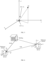
- the azimuth of arrival AOA is an included angle of a second projection vector in an X-axis direction, and a second reflection point is a reflection point closest to a signal receiving device. If there are a plurality of reflection points between a signal sending device and the signal receiving device, a first reflection point is different from the second reflection point; or if there is one reflection point between a signal sending device and the signal receiving device, a first reflection point is the same as the second reflection point.
- the zenith of arrival ZOA is an included angle of a vector formed by a connection line between the signal receiving device and the second reflection point in a Z-axis direction, and a projection vector of the vector formed by the connection line between the signal receiving device and the second reflection point on an X-Y plane is the second projection vector.
- the azimuth of departure AOD is an included angle of a first projection vector in the X-axis direction, and the first reflection point is a reflection point closest to the signal sending device.
- the zenith of departure ZOD is an included angle of a vector formed by a connection line between the signal sending device and the first reflection point in the Z-axis direction, and a projection vector of the vector formed by the connection line between the signal sending device and the first reflection point on the X-Y plane is the first projection vector.
- FIG. 4 is a diagram of the ZOD and the AOD according to an embodiment of this application.
- the TX is the signal sending device, and is also referred to as a transmit end, and Q1 is the first reflection point.
- the TX is the network device in FIG. 3 . If a communication path is the NLOS path 1, the first reflection point is a building 1 in FIG. 3 ; or if a communication path is the NLOS path 2, the first reflection point is a building 2 in FIG. 3 .
- the ZOD ⁇ 1
- FIG. 5 is a diagram of the ZOA and the AOA according to an embodiment of this application.
- the RX is the signal receiving device, and is also referred to as a receive end, and Q2 is the second reflection point.
- the RX is the terminal device in FIG. 3 . If a communication path is the NLOS path 1, the first reflection point is a building 1 in FIG. 3 ; or if a communication path is the NLOS path 2, the first reflection point is a building 2 in FIG. 3 .
- the ZOA ⁇ 2
- the AOA ⁇ 2 .
- one path parameter group includes the delay ⁇ , the attenuation A, the azimuth of arrival AOA, the zenith of arrival ZOA, the azimuth of departure AOD, and the zenith of departure ZOD. That is, a multiple-input multiple-output system is used as an example for description.
- the first information mainly indicates the K path parameter groups in the following two manners.
- N 3.
- the three path parameter groups are respectively a path parameter group 1, a path parameter group 2, and a path parameter group 3.
- the path parameter group 1 [ ⁇ 1 , A 1 , AOA 1 , ZOA 1 , AOD 1 , ZOD 1 ]
- the path parameter group 2 [ ⁇ 2 , A 2 , AOA 2 , ZOA 2 , AOD 2 , ZOD 2 ]
- the path parameter group 3 [ ⁇ 3 , A 3 , AOA 3 , ZOA 3 , AOD 3 , ZOD 3 ].
- the first information may include [ ⁇ 1 , A 1 , AOA 1 , ZOA 1 , AOD 1 , ZOD 1 ], [ ⁇ 2 , A 2 , AOA 2 , ZOA 2 , AOD 2 , ZOD 2 ], and [ ⁇ 3 , A 3 , AOA 3 , ZOA 3 , AOD 3 , ZOD 3 ] .
- a transmission periodicity of the K path parameter groups may be T1.
- a value of the transmission periodicity T1 is determined by a movement speed of the terminal device. Specifically, a higher movement speed of the terminal device indicates a shorter periodicity T1, and a lower movement speed of the terminal device indicates a longer periodicity T1.
- the first information includes W reference path parameter groups corresponding to W types of path parameter groups and difference information corresponding to each reference path parameter group, and W is a positive integer less than K.
- W is a positive integer less than K.
- One type of path parameter group corresponds to one reference path parameter group, and the W types of path parameter groups are obtained by classifying the K path parameter groups.
- the first device may classify the K path parameter groups to obtain the W types of path parameter groups.
- the first device determines the W reference path parameter groups corresponding to the W types of path parameter groups.
- One type of path parameter group corresponds to one reference path parameter group.
- the first device determines difference information between a path parameter group in each type of path parameter group and a reference path parameter group corresponding to each type of path parameter group, and sends the W reference path parameter groups and the difference information corresponding to each reference path parameter group as the first information to the second device.
- There may be a plurality of classification methods for example, a K-mean algorithm (K-mean algorithm) and a density-based spatial clustering of applications with noise (density-based spatial clustering of applications with noise, DBSCAN) algorithm.
- K-mean algorithm K-mean algorithm
- DBSCAN density-based spatial clustering of applications with noise
- a first-type path parameter group corresponds to a first reference path parameter group
- the first-type path parameter group includes at least one path parameter group
- the first-type path parameter group is any one of the W types of path parameter groups
- the first reference path parameter group may be determined based on the at least one path parameter group.
- the first reference path parameter group may be one of the at least one path parameter group, or the first reference path parameter group may be a path parameter group mean of the at least one path parameter group.
- a reference path parameter group corresponding to a type of path parameter group in this embodiment of this application may be a path parameter group determined from at least one path parameter group included in the type of path parameter group, or a reference path parameter group corresponding to a type of path parameter group may be a path parameter group mean of at least one path parameter group included in the type of path parameter group.
- N 7.
- the seven path parameter groups are respectively a path parameter group 1, a path parameter group 2, a path parameter group 3, a path parameter group 4, a path parameter group 5, a path parameter group 6, and a path parameter group 7.
- the path parameter group 1 [ ⁇ 1 , A 1 , AOA 1 , ZOA 1 , AOD 1 , ZOD 1 ]
- the path parameter group 2 [ ⁇ 2 , A 2 , AOA 2 , ZOA 2 , AOD 2 , ZOD 2 ]
- the path parameter group 3 [ ⁇ 3 , A 3 , AOA 3 , ZOA 3 , AOD 3 , ZOD 3 ]
- the path parameter group 4 [ ⁇ 4 , A 4 , AOA 4 , ZOA 4 , AOD 4 , ZOD 4 ],
- the path parameter group 5 [ ⁇ 5 , A 5 , AOA 5 , ZOA 5 , AOD 5 , ZOD 5 ],
- the path parameter group 6 [ ⁇ 6 , A 6 , AOA 6 , ZOA 6 , AOD 6 , ZOD 6 ],
- the path parameter group 7 [ ⁇ 7 , A 7 , AOA 7 , ZOA 7 , AOD 7 , ZOD
- a first-type path parameter group includes the path parameter group 1, the path parameter group 2, the path parameter group 3, and the path parameter group 4, and a second-type path parameter group includes the path parameter group 5, the path parameter group 6, and the path parameter group 7.
- a reference path parameter group 1 corresponding to the first-type path parameter group is the path parameter group 1
- a reference path parameter group corresponding to the second-type path parameter group is the path parameter group 5.
- differential calculation is separately performed on the path parameter group 2, the path parameter group 3, and the path parameter group 4 with the path parameter group 1, to obtain difference information 2-1, difference information 3-1, and difference information 4-1.
- the difference information 4-1 the path parameter group 4-the path parameter group 1.
- Differential calculation is separately performed on the path parameter group 6 and the path parameter group 7 with the path parameter group 5, to obtain difference information 6-5 and difference information 7-5.
- the difference information 2-1 [ ⁇ 2 - ⁇ 1 , A 2 - A 1 , AOA 2 - AOA 1 , ZOA 2 - ZOA 1 , AOD 2 - AOD 1 , ZOD 2 - ZOD 1 ],
- the difference information 3-1 [ ⁇ 3 - ⁇ 1 , A 3 - A 1 , AOA 3 - AOA 1 , ZOA 3 - ZOA 1 , AOD 3 - AOD 1 , ZOD 3 - ZOD 1 ], and
- the difference information 4-1 [ ⁇ 4 - ⁇ 1 , A 4 - A 1 , ADA 4 - ADA 1 , ZOA 4 - ZOA 1 , AOD 4 - AOD 1 , ZOD 4 - ZOD 1 ].
- the first information may include the reference path parameter group 1 (namely, the path parameter group 1), difference information (to be specific, the difference information 2-1, the difference information 3-1, and the difference information 4-1) corresponding to the reference path parameter group 1, the reference path parameter group 2 (namely, the path parameter group 5), and difference information (to be specific, the difference information 6-5 and the difference information 7-5) corresponding to the reference path parameter group 2.
- the reference path parameter group 1 namely, the path parameter group 1
- difference information to be specific, the difference information 2-1, the difference information 3-1, and the difference information 4-1 corresponding to the reference path parameter group 1
- the reference path parameter group 2 namely, the path parameter group 5
- difference information to be specific, the difference information 6-5 and the difference information 7-5) corresponding to the reference path parameter group 2.
- the first information includes [ ⁇ 1 , A 1 , AOA 1 , ZOA 1 , AOD 1 , ZOD 1 ], [ ⁇ 2 - ⁇ 1 , A 2 - A 1 , AOA 2 - AOA 1 , ZOA 2 - ZOA 1 , AOD 2 - AOD 1 , ZOD 2 - ZOD 1 ], [ ⁇ 3 - ⁇ 1 , A 3 - A 1 , AOA 3 - AOA 1 , ZOA 3 - ZOA 1 , AOD 3 - AOD 1 , ZOD 3 - ZOD 1 ], [ ⁇ 4 - ⁇ 1 , A 4 - A 1 , AOA 4 - AOA 1 , ZOA 4 - ZOA 1 , AOD 4 - AOD 1 , ZOD 4 - ZOD 1 ], [ ⁇ 5 , A 5 , AOA 5 , ZOA 5 , AOD 5 , ZOD 5 ], [ ⁇ 6 - ⁇ 5 , AOA
- a reference path parameter group 1 corresponding to the first-type path parameter group is a reference path parameter group mean 1 of the path parameter group 1 to the path parameter group 4
- a reference path parameter group corresponding to the second-type path parameter group is a path parameter group mean 2 of the path parameter group 5 to the path parameter group 7.
- differential calculation is separately performed on the path parameter group 1, the path parameter group 2, the path parameter group 3, and the path parameter group 4 with the reference path parameter group mean 1, to obtain difference information 1, difference information 2, difference information 3, and difference information 4.
- the difference information 1 the path parameter group 1-the reference path parameter group mean 1
- the difference information 2 the path parameter group 2-the reference path parameter group 1
- the difference information 3 the path parameter group 3-the reference path parameter group 1
- the difference information 4 the path parameter group 4-the reference path parameter group 1.
- Differential calculation is separately performed on the path parameter group 5, the path parameter group 6, and the path parameter group 7 with the path parameter group mean 2, to obtain difference information 5, difference information 6, and difference information 7.
- the difference information 5 the path parameter group 5-the path parameter group mean 2
- the difference information 6 the path parameter group 6-the path parameter group 5
- the difference information 7 the path parameter group 7-the path parameter group 5.
- the difference information 1 ⁇ 1 ⁇ ⁇ 1 + ⁇ 2 + ⁇ 3 + ⁇ 4 4 , A 1 ⁇ A 1 + A 2 + A 3 + A 4 4 , AOA 1 ⁇ AOA 1 + AOA 2 + AOA 3 + AOA 4 4 , ZOA 1 ⁇ ZOA 1 + ZOA 2 + ZOA 3 + ZOA 4 4 , AOD 1 ⁇ AOD 1 + AOD 2 + AOD 3 + AOD 4 4 , ZOD 1 ⁇ ZOD 1 + ZOD 2 + ZOD 3 + ZOD 4 4 ,
- the difference information 2 ⁇ 2 ⁇ ⁇ 1 + ⁇ 2 + ⁇ 3 + ⁇ 4 4 , A 2 ⁇ A 1 + A 2 + A 3 + A 4 4 , AOA 2 ⁇ AOA 1 + AOA 2 + AOA 3 + AOA 4 4 , ZOA 2 ⁇ ZOA 1 + ZOA 2 + ZOA 3 + ZOA 4 4 , AOD 2 ⁇ AOD 1 + AOD 2 + AOD 3 + AOD 4 4 , ZOD 2 ⁇ ZOD 1 + ZOD 2 + ZOD 3 + ZOD 4 4 .
- the difference information 3 ⁇ 3 ⁇ ⁇ 1 + ⁇ 2 + ⁇ 3 + ⁇ 4 4 , A 3 ⁇ A 1 + A 2 + A 3 + A 4 4 , AOA 3 ⁇ AOA 1 + AOA 2 + AOA 3 + AOA 4 4 , ZOA 3 ⁇ ZOA 1 + ZOA 2 + ZOA 3 + ZOA 4 4 , AOD 3 ⁇ AOD 1 + AOD 2 + AOD 3 + AOD 4 4 , ZOD 3 ⁇ ZOD 1 + ZOD 2 + ZOD 3 + ZOD 4 4 .
- the difference information 4 ⁇ 4 ⁇ ⁇ 1 + ⁇ 2 + ⁇ 3 + ⁇ 4 4 , A 4 ⁇ A 1 + A 2 + A 3 + A 4 4 , AOA 4 ⁇ AOA 1 + AOA 2 + AOA 3 + AOA 4 4 , ZOA 4 ⁇ ZOA 1 + ZOA 2 + ZOA 3 + ZOA 4 4 , AOD 4 ⁇ AOD 1 + AOD 2 + AOD 3 + AOD 4 4 , ZOD 4 ⁇ ZOD 1 + ZOD 2 + ZOD 3 + ZOD 4 4 ,
- the difference information 5 ⁇ 5 ⁇ ⁇ 5 + ⁇ 6 + ⁇ 7 3 , A 5 ⁇ A 5 + A 6 + A 7 3 , AOA 5 ⁇ AOA 5 + AOA 6 + AOA 7 3 , ZOA 5 ⁇ ZOA 5 + ZOA 6 + ZOA 7 3 , AOD 5 ⁇ AOD 5 + AOD 6 + AOD 7 3 , ZOD 5 ⁇ ZOD 5 + ZOD 6 + ZOD 7 3
- the difference information 6 ⁇ 6 ⁇ ⁇ 5 + ⁇ 6 + ⁇ 7 3 , A 6 ⁇ A 5 + A 6 + A 7 3 , AOA 6 ⁇ AOA 5 + AOA 6 + AOA 7 3 , ZOA 6 ⁇ ZOA 5 + ZOA 6 + ZOA 7 3 AOD 6 ⁇ AOD 5 + AOD 6 + AOD 7 3 , ZOD 6 ⁇ ZOD 5 + ZOD 6 + ZOD 7 3
- the difference information 7 ⁇ 7 ⁇ ⁇ 5 + ⁇ 6 + ⁇ 7 3 , A 7 ⁇ A 5 + A 6 + A 7 3 , AOA 7 ⁇ AOA 5 + AOA 6 + AOA 7 3 , ZOA 7 ⁇ ZOA 5 + ZOA 6 + ZOA 7 3 , AOD 7 ⁇ AOD 5 + AOD 6 + AOD 7 3 , ZOD 7 ⁇ ZOD 5 + ZOD 6 + ZOD 7 3 .
- a transmission periodicity of the W reference path parameter groups may be T0
- a transmission periodicity of the difference information may be T3.
- Values of the transmission periodicity T0 and the transmission periodicity T3 are determined by a movement speed of the terminal device. Specifically, a higher movement speed of the terminal device indicates a shorter periodicity T0 and a shorter periodicity T3, and a lower movement speed of the terminal device indicates a longer periodicity T0 and a longer periodicity T3.
- T0 may be greater than T3.
- S302 Correct the K path parameter groups based on path parameter group search range information, and perform channel estimation based on K corrected path parameter groups.
- the second device may correct the K path parameter groups based on the path parameter group search range information, and perform channel estimation based on the K corrected path parameter groups.
- the path parameter group search range information may include at least one of the following information: delay search range information, attenuation search range information, azimuth of arrival search range information, zenith of arrival search range information, azimuth of departure search range information, and zenith of departure search range information.
- Path parameter search range information of any path parameter ⁇ may be a specific value.
- the value may be represented as ⁇ .
- a search range of the path parameter ⁇ may be represented as [ ⁇ - ⁇ , ⁇ + ⁇ ].
- the delay search range information may be ⁇ ⁇
- the attenuation search range information may be ⁇ A
- the azimuth of arrival search range information may be ⁇ AOA
- the zenith of arrival search range information may be ⁇ ZOA
- the azimuth of departure search range information may be ⁇ AOD
- the zenith of departure search range information may be ⁇ ZOD .
- a search range of a delay is [ ⁇ - ⁇ ⁇ , ⁇ + ⁇ ⁇ ]
- a search range of attenuation is [ A - ⁇ A , A + ⁇ A ]
- a search range of an azimuth of arrival is [ AOA - ⁇ AOA , AOA+ ⁇ AOA]
- a search range of a zenith of arrival is [ ZOA- ⁇ ZOA , ZOA + ⁇ ZOA ]
- a search range of an azimuth of departure is [AOD- ⁇ AOD, AOD+ ⁇ AOD ]
- a search range of a zenith of departure is [ZOD- ⁇ ZOD, ZOD + ⁇ ZOD ].
- the path parameter group search range information corresponding to any path parameter may alternatively be a standard deviation of the path parameter measurement values.
- the standard deviation of the path parameter measurement values may be represented as ⁇ . Therefore, any path parameter may be searched in a range of [ ⁇ - ⁇ , ⁇ + ⁇ ] with a probability of 68.2%, searched in a range of [ ⁇ - 2 ⁇ , ⁇ + 2 ⁇ ] with a probability of 95.4%, and searched in a range of [ ⁇ - 3 ⁇ , ⁇ + 3 ⁇ ] with a probability of 99.8%.
- the delay is used as an example.
- a transmission periodicity of the path parameter group search range information sent by the first device sends to the second device may be T2, where T2 is determined by a sensing precision change. Specifically, a faster sensing precision change indicates a shorter periodicity T2, and a slower sensing precision change indicates a longer periodicity T2.
- the transmission periodicity T1 of the K path parameter groups may be different from the transmission periodicity T2 of the path parameter group search range information. Generally, T1 may be greater than T2. In some feasible implementations, T1 may alternatively be less than T2. This is not limited herein.
- the transmission periodicity T1 of the K path parameter groups may alternatively be the same as the transmission periodicity T2 of the path parameter group search range information.
- the K path parameter groups and the path parameter group search range information may be sent by using one piece of signaling, or may be separately sent by using two pieces of signaling. This is specifically determined based on an actual application scenario, and is not limited herein.
- the transmission periodicity (T1, T2, and/or T3) may be statically or semi-statically configured by using the signaling at the layer above the physical layer, and the transmission periodicity (T1, T2, and/or T3) may be configured in real time by using the physical layer signaling.
- the path parameter group search range information may alternatively be determined by the second device based on the K path parameter groups at a plurality of moments.
- the second device may obtain a standard deviation of path parameters based on historical empirical data.
- the second device may calculate a standard deviation of path parameters in a first path parameter group at a plurality of historical moments, and further determine the path parameter group search range information based on K standard deviations corresponding to the K path parameter groups.
- the first path parameter group is any one of the K path parameter groups.
- the second device may alternatively perform theoretical derivation (for example, the cramer-rao lower bound (cramer-rao lower bound, CRLB) theory) based on a location error of a transceiver and an environment reconstruction error, to obtain search range information of path parameters. Further, the second device may correct the K path parameter groups based on the calculated path parameter group search range information, and perform channel estimation based on the K corrected path parameter groups.
- theoretical derivation for example, the cramer-rao lower bound (cramer-rao lower bound, CRLB) theory
- the path parameter group search range information may alternatively be pre-specified in a protocol. Therefore, the second device may correct the K path parameter groups based on the path parameter group search range information pre-specified in the protocol, and perform channel estimation based on the K corrected path parameter groups.
- correcting the K path parameter groups based on the path parameter group search range information in this embodiment of this application may be understood as: calculating a group of path parameters based on a small quantity of measurement pilots within the given K path parameter groups and the path parameter group search range information, where an error between a pilot response obtained through calculation based on the group of path parameters and a pilot response obtained through measurement is the smallest.
- the terminal device may determine path parameter groups of K corrected communication paths according to a formula (1) and a formula (2), that is, determine the K corrected path parameter groups according to the formula (1) and the formula (2).
- H ( f pilot ) in the formula (1) is a first channel estimation value
- A [ A 1 , A 2 , A K ], 4 in the formula (1) is a value in A 1 , A 2 , ⁇ A K
- A is a vector formed by amplitudes of the K corrected communication paths.
- ⁇ [ ⁇ 1 , ⁇ 2 , ⁇ , ⁇ K ] is a vector formed by amplitudes of K communication paths
- ⁇ [ ⁇ 1, ⁇ 2 , ⁇ , ⁇ K ]
- ⁇ k in the formula (1) is a value in ⁇ 1 , ⁇ 2 , ⁇ , ⁇ K
- ⁇ is a vector formed by delays of the K corrected communication paths
- ⁇ [ ⁇ 1 , ⁇ 2 , ⁇ ⁇ K ] is a vector formed by delays of the K communication paths
- ⁇ 1 is a preset value corresponding to the amplitude
- ⁇ 2 is a preset value corresponding to the delay.
- a 2 and ⁇ 2 are a path parameter group of a 2 nd communication path
- ⁇ K are a path parameter group of a K th communication path.
- ⁇ 1 is determined based on the delay search range information in the path parameter group search range information
- ⁇ 2 is determined based on the attenuation search range information in the path parameter group search range information.
- the first channel estimation value is a channel estimation value obtained through measurement by using the small quantity of pilots
- the second channel estimation value is a channel estimation value obtained based on the K corrected path parameter groups corrected by using the small quantity of pilots.
- a small quantity of pilots need to be inserted into sent data to correct the path parameter.
- the terminal device may determine path parameter groups of K corrected communication paths according to a formula (1) and a formula (2) includes: The terminal device may determine the path parameter groups of the K corrected communication paths according to the formula (1) and the formula (2) by using a maximum likelihood algorithm, a heuristic intelligent search method, or an exhaustive method.
- the terminal device determines the path parameter group of each of the K communication paths according to the formula (1) and the formula (2) is for a case of single-input single-output of the network device and the terminal device.
- the network device sends first data by using one antenna, and the terminal device receives the first data by using one antenna.
- the network device may send first data by using a plurality of antennas, and the terminal device may receive the first data by using a plurality of antennas.
- the formula (1) may be changed to a formula (3)
- the formula (2) may be changed to a formula (4).
- ⁇ k m , n is a delay of the pilot sent by using the m th antenna in the M antennas of the network device and received by using the n th antenna in the N antennas of the terminal device.
- H m , n ( f pilot ) in the formula (3) is a first channel estimation value of the pilot when the pilot is sent by using the m th antenna of the network device and received by using the n th antenna of the terminal device
- ⁇ k 1 K A k m , n exp ⁇ j 2 ⁇ f pilot ⁇ k m , n in the formula (3) is a second channel estimation value of the pilot when the pilot is sent by using the m th antenna of the network device and received by using the n th antenna of the terminal device.
- a m , n A 1 m , n A 2 m , n ⁇ A K m , n , A k m , n in the formula (1) is a value in A 1 m , n , A 2 m , n , ⁇ , A K m , n , and A m , n is the vector formed by the amplitudes of the K corrected communication paths.
- FIG. 6 is a diagram of a communication path in a downlink transmission scenario in a multi-antenna scenario according to an embodiment of this application.
- FIG. 6 shows a scenario in which the first data is sent by using one antenna combination.
- Each antenna combination corresponds to a same quantity of communication paths.
- each antenna combination corresponds to a same quantity of communication paths. For example: If a 1 st antenna of the network device and a 1 st antenna of the terminal device correspond to one NLOS, a 2 nd antenna of the network device and the 1 st antenna of the terminal device correspond to one NLOS.
- the network device may sequentially determine a path parameter group of at least one communication path corresponding to each of the M*N antenna combinations, and then correct the path parameter group corresponding to each antenna combination.
- the network device may determine a path parameter group of an antenna path of another antenna combination based on a path parameter group of a communication path of one antenna combination, and correct a path parameter group corresponding to each antenna combination.
- the network device may determine, based on S201, that a path parameter group of K communication paths between the 1 st antenna of the network device and the 1 st antenna of the terminal device is ⁇ k 1 , 1 , A k 1 , 1 , AOD k 1 , 1 , ZOD k 1 , 1 , AOA k 1 , 1 , ZOA k 1 , 1 k ⁇ 1 K , where a superscript (1, 1) represents the 1 st antenna of the network device and the 1 st antenna of the terminal device.
- a path parameter group of K communication paths of an n th antenna of the terminal device is ⁇ k m , n , A k m , n , AOD k m , n , ZOD k m , n , AOA k m , n , ZOA k m , n k ⁇ 1 K .
- ⁇ k m , n , A k m , n , AOD k m , n , ZOD k m , n , AOA k m , n k ⁇ 1 K may be obtained based on ⁇ k 1 , 1 , A k 1 , 1 , AOD k 1 , 1 , ZOD k 1 , 1 , AOA k 1 , 1 , ZOA k 1 , 1 k ⁇ 1 K .
- a delay ⁇ k m , n of the m th antenna of the network device and the n th antenna of the terminal device may be obtained based on a sum of a delay ⁇ k 1 , 1 of the 1 st antenna of the network device and the 1 st antenna of the terminal device, the delay difference ⁇ ⁇ k tx , m between the m th antenna and the 1 st antenna of the network device, and the delay difference between the n th antenna and the 1 st antenna of the terminal device.
- x tx m for calculating ⁇ ⁇ k tx , m in the formula (6) is a coordinate of the m th antenna of the network device on an X axis
- x tx 1 is a coordinate of the 1 st antenna of the network device on the X axis
- y tx m is coordinate of the m th antenna of the network device on a Y axis
- y tx 1 is a coordinate of the 1 st antenna of the network device on the Y axis.
- z tx m is a coordinate of the m th antenna of the network device on a Z axis
- z tx 1 is a coordinate of the 1 st antenna of the network device on the Z axis.
- x tx m ⁇ x tx 1 , y tx m ⁇ y tx 1 , and z tx m ⁇ z tx 1 may be obtained based on a physical relationship between the m th antenna and the 1 st antenna of the network device.
- x rx n for calculating ⁇ ⁇ k rx , n in the formula (7) is a coordinate of the n th antenna of the terminal device on the X axis
- x rx 1 is a coordinate of the 1 st antenna of the terminal device on the X axis
- y rx n is a coordinate of the n th antenna of the terminal device on the Y axis
- y rx 1 is a coordinate of the 1 st antenna of the terminal device on the Y axis.
- z rx n is a coordinate of the n th antenna of the terminal device on the Z axis
- z rx 1 is a coordinate of the 1 st antenna of the terminal device on the Z axis.
- x rx n ⁇ x rx 1 , y rx n ⁇ y rx 1 , and z rx n ⁇ z rx 1 may be obtained based on a physical relationship between the n th antenna and the 1 st antenna of the terminal device.
- ⁇ k m , n is determined based on ⁇ k 1 , 1 , AOD k 1 , 1 , ZOD k 1 , 1 , AOA k 1 , 1 , and ZOA k 1 , 1 .
- an amplitude A k m , n of a k th communication path between the m th antenna of the network device and the n th antenna of the terminal device is equal to A k 1 , 1 .
- AOD k m , n of the k th communication path between the m th antenna of the network device and the n th antenna of the terminal device is equal to AOD k 1 , 1 .
- ZOD k m , n of the k th communication path between the m th antenna of the network device and the n th antenna of the terminal device is equal to ZOD k 1 , 1 .
- AOA k m , n of the k th communication path between the m th antenna of the network device and the n th antenna of the terminal device is equal to AOA k 1 , 1 .
- ZOA k m , n of the k th communication path between the m th antenna of the network device and the n th antenna of the terminal device is equal to ZOA k 1 , 1 .
- performing channel estimation based on the K corrected path parameter groups in this embodiment of this application may be understood as: obtaining a channel response on each frequency through calculation based on the corrected path parameter.
- the path parameter corresponds to information about a channel.
- channel responses on different frequencies may be derived.
- the single-input single-output is used as an example.
- the second device may further demodulate, based on the channel estimation, communication data received by the second device.
- the communication data may be communication data sent by the first device to the second device.
- the communication data may alternatively be communication data sent by another device (for example, the third device) to the second device, or the like. This is not limited herein.
- the first device is different from the third device.
- an estimated value of H and Y are given, an estimated value of X is obtained by using an algorithm.
- a channel estimation algorithm is a least square (least square, LS) algorithm.
- LS least square
- ⁇ LS is a result of the channel estimation.
- the K path parameter groups are fed back for channel estimation, to reduce pilot overheads.
- the path parameter group search range information is obtained to correct the K path parameter groups, to effectively reduce calculation complexity of the receive end.
- the K path parameter groups and the path parameter group search range information are updated by using different periodicities, to reduce feedback overheads.
- a differential feedback manner is used for the K path parameter groups, to further reduce the feedback overheads.
- the path parameter group in this embodiment of this application may be further used for beam sweeping between the first device and the second device.
- path parameters may be estimated based on TX and RX locations and environment information, and a plurality of paths are sorted based on strength of the path parameters.
- a path with strongest energy may be selected, and at least one of an AOA, a ZOA, an AOD, or a ZOD corresponding to the path with strongest energy is found.
- the transmit end may form a beam based on the AOD and/or the ZOD and transmit a signal
- the receive end forms a beam based on the AOA and/or the ZOA and receives the signal.
- FIG. 7 is a diagram of a structure of a communication apparatus according to an embodiment of this application.
- the communication apparatus shown in FIG. 7 may be configured to perform some or all functions of the first device in the method embodiment described in FIG. 3 .
- the apparatus may be the first device, may be an apparatus in the first device, or may be an apparatus that can be used together with the first device.
- the communication apparatus may alternatively be a chip system.
- the communication apparatus shown in FIG. 7 may include a transceiver unit 701 and a processing unit 702.
- the processing unit 702 is configured to perform data processing.
- the transceiver unit 701 is integrated with a receiving unit and a sending unit.
- the transceiver unit 701 may also be referred to as a communication unit.
- the transceiver unit 701 may be split into a receiving unit and a sending unit.
- the descriptions of the processing unit 702 below are similar to those of the transceiver unit 701, and details are not described below again.
- the processing unit 702 is configured to determine path parameter group search range information and first information, where the first information indicates K path parameter groups, and K is an integer greater than 0.
- the transceiver unit 701 is configured to send the path parameter group search range information and the first information to a second device, where the path parameter group search range information is used to correct the K path parameter groups, and K corrected path parameter groups are used for channel estimation.
- the first information includes the K path parameter groups.
- the first information includes W reference path parameter groups corresponding to W types of path parameter groups and difference information corresponding to each reference path parameter group, and W is a positive integer less than K.
- W is a positive integer less than K.
- One type of path parameter group corresponds to one reference path parameter group, and the W types of path parameter groups are obtained by classifying the K path parameter groups.
- a first-type path parameter group corresponds to a first reference path parameter group
- the first-type path parameter group includes at least one path parameter group
- the first-type path parameter group is any one of the W types of path parameter groups
- the first reference path parameter group is determined based on the at least one path parameter group.
- the first reference path parameter group is one of the at least one path parameter group, or the first reference path parameter group is a path parameter group mean of the at least one path parameter group.
- a transmission periodicity of the K path parameter groups is T1
- a transmission periodicity of the path parameter group search range information is T2, where T1 is different from T2.
- a transmission periodicity of the W reference path parameter groups is T0
- a transmission periodicity of the path parameter group search range information is T2
- a transmission periodicity of the difference information is T3, where T0 is greater than T3, and T2 is greater than T3.
- one path parameter group includes at least one of the following parameters: a delay ⁇ , attenuation A, an azimuth of arrival AOA, a zenith of arrival ZOA, an azimuth of departure AOD, and a zenith of departure ZOD.
- the path parameter group search range information includes at least one of the following information: delay search range information, attenuation search range information, azimuth of arrival search range information, zenith of arrival search range information, azimuth of departure search range information, and zenith of departure search range information.
- FIG. 8 is a diagram of a structure of another communication apparatus according to an embodiment of this application.
- the communication apparatus shown in FIG. 8 may be configured to perform some or all functions of the second device in the method embodiment described in FIG. 3 .
- the apparatus may be the second device, may be an apparatus in the second device, or may be an apparatus that can be used together with the second device.
- the communication apparatus may alternatively be a chip system.
- the communication apparatus shown in FIG. 8 may include a transceiver unit 801 and a processing unit 802.
- the transceiver unit 801 is configured to receive first information from a first device, where the first information indicates K path parameter groups, and K is an integer greater than 0.
- the processing unit 802 is configured to: correct the K path parameter groups based on path parameter group search range information, and perform channel estimation based on K corrected path parameter groups.
- the path parameter group search range information is configured by the first device; the path parameter group search range information is determined based on the K path parameter groups at a plurality of moments; or the path parameter group search range information is pre-specified in a protocol.
- the first information includes the K path parameter groups.
- the first information includes W reference path parameter groups corresponding to W types of path parameter groups and difference information corresponding to each reference path parameter group, and W is a positive integer less than K.
- W is a positive integer less than K.
- One type of path parameter group corresponds to one reference path parameter group, and the W types of path parameter groups are obtained by classifying the K path parameter groups.
- a first-type path parameter group corresponds to a first reference path parameter group
- the first-type path parameter group includes at least one path parameter group
- the first-type path parameter group is any one of the W types of path parameter groups
- the first reference path parameter group is determined based on the at least one path parameter group.
- the first reference path parameter group is one of the at least one path parameter group, or the first reference path parameter group is a path parameter group mean of the at least one path parameter group.
- a transmission periodicity of the K path parameter groups is T1
- a transmission periodicity of the path parameter group search range information is T2, where T1 is different from T2.
- a transmission periodicity of the W reference path parameter groups is T0
- a transmission periodicity of the path parameter group search range information is T2
- a transmission periodicity of the difference information is T3, where T0 is greater than T3, and T2 is greater than T3.
- one path parameter group includes at least one of the following parameters: a delay ⁇ , attenuation A, an azimuth of arrival AOA, a zenith of arrival ZOA, an azimuth of departure AOD, and a zenith of departure ZOD.
- the path parameter group search range information includes at least one of the following information: delay search range information, attenuation search range information, azimuth of arrival search range information, zenith of arrival search range information, azimuth of departure search range information, and zenith of departure search range information.
- FIG. 9 is a diagram of a structure of another communication apparatus according to an embodiment of this application.
- the communication apparatus may be the second device described in embodiments of this application, and is configured to implement functions of the second device in FIG. 3 .
- the second device may be an access network device, or may be a terminal device.
- FIG. 9 shows only main components of a terminal device 900.
- the terminal device 900 includes a processor, a memory, a control circuit, an antenna, and an input/output apparatus.
- the processor is mainly configured to: process a communication protocol and communication data, control the entire terminal device 900, execute a software program, and process data of the software program.
- the memory is mainly configured to store the software program and the data.
- the control circuit is mainly configured to: perform conversion between a baseband signal and a radio frequency signal, and process the radio frequency signal.
- the antenna is mainly configured to send and receive the radio frequency signal in a form of an electromagnetic wave.
- the input/output apparatus for example, a touchscreen, a display, a microphone, or a keyboard, is mainly configured to receive data input by a user and output data to the user.
- the terminal device 900 is a mobile phone.
- the processor may read a software program in a storage unit, explain and execute instructions of the software program, and process data of the software program.
- the processor performs baseband processing on the to-be-sent data, and then outputs a baseband signal to the control circuit.
- the control circuit performs radio frequency processing on the baseband signal, and then sends a radio frequency signal to the outside in the form of an electromagnetic wave through the antenna.
- the control circuit receives the radio frequency signal through the antenna, converts the radio frequency signal into a baseband signal, and outputs the baseband signal to the processor.
- the processor converts the baseband signal into data, and processes the data.
- FIG. 9 shows only one memory and one processor.
- the terminal device 900 may include a plurality of processors and memories.
- the memory may also be referred to as a storage medium, a storage device, or the like. This is not limited in embodiments of this application.
- the processor may include a baseband processor and a central processing unit.
- the baseband processor is mainly configured to process the communication protocol and the communication data.
- the central processing unit is mainly configured to: control the entire terminal device 900, execute the software program, and process the data of the software program. Functions of the baseband processor and the central processing unit are integrated into the processor in FIG. 9 .
- the baseband processor and the central processing unit each may be an independent processor, and are interconnected by using a technology such as a bus.
- the terminal device 900 may include a plurality of baseband processors to adapt to different network standards, and the terminal device 900 may include a plurality of central processing units to enhance a processing capability of the terminal device 900.
- the antenna and the control circuit that have sending and receiving functions may be considered as a transceiver unit 910 of the terminal device 900, and the processor having a processing function may be considered as a processing unit 920 of the terminal device 900.
- the terminal device 900 includes the transceiver unit 910 and the processing unit 920.
- the transceiver unit may also be referred to as a transceiver, a transceiver machine, a transceiver apparatus, or the like.
- a component that is in the transceiver unit 910 and that is configured to implement the receiving function may be considered as a receiving unit
- a component that is in the transceiver unit 910 and that is configured to implement the sending function may be considered as a sending unit.
- the transceiver unit 910 includes the receiving unit and the sending unit.
- the receiving unit may also be referred to as a receiver machine, a receiver, a receiver circuit, or the like.
- the sending unit may be referred to as a transmitter machine, a transmitter, a transmitter circuit, or the like.
- FIG. 10 is a diagram of a structure of another communication apparatus according to an embodiment of this application.
- the communication apparatus may be the first device described in embodiments of this application, and is configured to implement functions of the first device in FIG. 3 .
- the first device may be an access network device, or may be a terminal device.
- FIG. 10 is mainly described by using an example in which the first device is an access network device.
- the first device includes a baseband apparatus 101, a radio frequency apparatus 102, and an antenna 103.
- the radio frequency apparatus 102 receives, through the antenna 103, information sent by the terminal device, and sends the information sent by the terminal device to the baseband apparatus 101 for processing.
- the baseband apparatus 101 processes information from the terminal device and sends processed information to the radio frequency apparatus 102
- the radio frequency apparatus 102 processes the information from the terminal device and then sends processed information to the terminal device through the antenna 103.
- the baseband apparatus 101 includes one or more processing units 1011, a storage unit 1012, and an interface 1013.
- the processing unit 1011 is configured to support the network device in performing functions of the network device in the foregoing method embodiments.
- the storage unit 1012 is configured to store a software program and/or data.
- the interface 1013 is configured to exchange information with the radio frequency apparatus 102.
- the interface includes an interface circuit, and is configured to input and output information.
- the processing unit is an integrated circuit, for example, one or more application-specific integrated circuits (application-specific integrated circuits, ASICs), one or more digital signal processors (digital signal processors, DSPs), one or more field programmable gate arrays (field programmable gate arrays, FPGAs), or a combination of such integrated circuits. These integrated circuits may be integrated together to form a chip.
- the storage unit 1012 may be located in a same chip as the processing unit 1011, that is, an on-chip storage element. Alternatively, the storage unit 1012 may be located on a different chip from the processing unit 1011, that is, an off-chip storage element.
- the storage unit 1012 may be one memory, or may be a collective name of a plurality of memories or storage elements.
- the first device may implement some or all of the steps in the foregoing method embodiments in a form of scheduling programs by using one or more processing units, for example, implement corresponding functions of the network device in FIG. 3 .
- the one or more processing units may support radio access technologies of a same standard, or may support radio access technologies of different standards.
- An embodiment of this application further provides a computer-readable storage medium.
- the computer-readable storage medium stores instructions, and when the instructions are run on a processor, method procedures in the foregoing method embodiments are implemented.
- An embodiment of this application further provides a computer program product.
- the computer program product runs on a processor, method procedures in the foregoing method embodiments are implemented.
- the disclosed systems, apparatuses, and methods may be implemented in other manners.
- the described apparatus embodiments are merely examples.
- division into the units is merely logical function division.
- the units described as separate components may or may not be physically separate, and components displayed as units may or may not be physical units, may be located at one location, or may be distributed on a plurality of network units. Some or all of the units may be selected based on actual requirements to achieve objectives of the solutions of embodiments.
- the functions When the functions are implemented in a form of a software functional unit and sold or used as an independent product, the functions may be stored in a computer-readable storage medium. Based on such an understanding, the technical solutions of this application essentially, or the part contributing to the conventional technology, or some of the technical solutions may be implemented in a form of a software product.
- the computer software product is stored in a storage medium, and includes several instructions for instructing a computer device (which may be a personal computer, a server, a network device, or the like) to perform all or some of the steps of the methods described in embodiments of this application.
- the foregoing computer-readable storage medium may be any usable medium that can be accessed by a computer.
- the computer-readable medium may include but is not limited to: a random access memory (random access memory, RAM), a read-only memory (read-only memory, ROM), a programmable read-only memory (programmable ROM, PROM), an erasable programmable read-only memory (erasable PROM, EPROM), an electrically erasable programmable read-only memory (electrically erasable programmable read-only memory, EEPROM), a compact disc read-only memory (compact disc read-only memory, CD-ROM), a universal serial bus flash disk (universal serial bus flash disk), a removable hard disk, another optical disc storage, a magnetic disk storage medium or another magnetic storage device, or any other medium that can be used to carry or store expected program code in a form of instructions or a data structure and that can be accessed by the computer.
- RAM random access memory
- ROM read-only memory
- PROM programmable read-only memory
- EPROM erasable programmable read-only memory
- EEPROM
- RAMs may be used, for example, a static random access memory (static RAM, SRAM), a dynamic random access memory (dynamic RAM, DRAM), a synchronous dynamic random access memory (synchronous DRAM, SDRAM), a double data rate synchronous dynamic random access memory (double data rate SDRAM, DDR SDRAM), an enhanced synchronous dynamic random access memory (enhanced SDRAM, ESDRAM), a synchronous link dynamic random access memory (synchlink DRAM, SLDRAM), or a direct rambus random access memory (direct rambus RAM, DR RAM).
- static random access memory static random access memory
- DRAM dynamic random access memory
- DRAM synchronous dynamic random access memory
- SDRAM double data rate synchronous dynamic random access memory
- double data rate SDRAM double data rate SDRAM
- ESDRAM enhanced synchronous dynamic random access memory
- SLDRAM synchronous link dynamic random access memory
- direct rambus RAM direct rambus RAM
Landscapes
- Engineering & Computer Science (AREA)
- Computer Networks & Wireless Communication (AREA)
- Signal Processing (AREA)
- Power Engineering (AREA)
- Mobile Radio Communication Systems (AREA)
Applications Claiming Priority (2)
| Application Number | Priority Date | Filing Date | Title |
|---|---|---|---|
| CN202210620651.5A CN117221051A (zh) | 2022-06-02 | 2022-06-02 | 通信方法及通信装置 |
| PCT/CN2023/097181 WO2023232040A1 (fr) | 2022-06-02 | 2023-05-30 | Procédé de communication et appareil de communication |
Publications (2)
| Publication Number | Publication Date |
|---|---|
| EP4529101A1 true EP4529101A1 (fr) | 2025-03-26 |
| EP4529101A4 EP4529101A4 (fr) | 2025-08-13 |
Family
ID=89026954
Family Applications (1)
| Application Number | Title | Priority Date | Filing Date |
|---|---|---|---|
| EP23815219.3A Pending EP4529101A4 (fr) | 2022-06-02 | 2023-05-30 | Procédé de communication et appareil de communication |
Country Status (4)
| Country | Link |
|---|---|
| US (1) | US20250097074A1 (fr) |
| EP (1) | EP4529101A4 (fr) |
| CN (1) | CN117221051A (fr) |
| WO (1) | WO2023232040A1 (fr) |
Families Citing this family (1)
| Publication number | Priority date | Publication date | Assignee | Title |
|---|---|---|---|---|
| EP4612976A4 (fr) * | 2022-11-02 | 2026-02-25 | Samsung Electronics Co Ltd | Procédé et appareil pour prendre en charge une auto-configuration et une auto-optimisation |
Family Cites Families (8)
| Publication number | Priority date | Publication date | Assignee | Title |
|---|---|---|---|---|
| US20110122963A1 (en) * | 2008-07-07 | 2011-05-26 | Jun Yuan | Codebook restructure, differential encoding/decoding, and scheduling |
| US8442449B2 (en) * | 2010-11-08 | 2013-05-14 | Telefonaktiebolaget L M Ericsson (Publ) | Receiver and method for reducing an amount of channel state information feedback to a transmitter |
| EP2768154A1 (fr) * | 2013-02-15 | 2014-08-20 | Alcatel Lucent | Récepteur et son moyen de fonctionnement |
| KR102403763B1 (ko) * | 2017-06-27 | 2022-05-30 | 삼성전자주식회사 | 무선 통신 시스템에서 명시적 채널 상태 정보 피드백을 위한 피드백 정보 설정하기 위한 방법 |
| CN111431638B (zh) * | 2019-01-10 | 2022-03-22 | 大唐移动通信设备有限公司 | 一种信道模型参数方法及装置 |
| CN111193679B (zh) * | 2020-01-09 | 2022-04-19 | 中国传媒大学 | 一种基于互质阵列系统的信道估计方法及系统 |
| CN111521969B (zh) * | 2020-04-17 | 2022-07-05 | 西北工业大学 | 基于Wi-Fi的被动式室内定位方法 |
| CN113225274B (zh) * | 2021-04-14 | 2023-11-03 | 西安宇飞电子技术有限公司 | 一种针对快速移动的多径信道模型测量方法 |
-
2022
- 2022-06-02 CN CN202210620651.5A patent/CN117221051A/zh active Pending
-
2023
- 2023-05-30 EP EP23815219.3A patent/EP4529101A4/fr active Pending
- 2023-05-30 WO PCT/CN2023/097181 patent/WO2023232040A1/fr not_active Ceased
-
2024
- 2024-12-02 US US18/965,662 patent/US20250097074A1/en active Pending
Also Published As
| Publication number | Publication date |
|---|---|
| EP4529101A4 (fr) | 2025-08-13 |
| WO2023232040A1 (fr) | 2023-12-07 |
| CN117221051A (zh) | 2023-12-12 |
| US20250097074A1 (en) | 2025-03-20 |
Similar Documents
| Publication | Publication Date | Title |
|---|---|---|
| US12538154B2 (en) | Methods and systems for managing reflecting surface | |
| EP4099574B1 (fr) | Dispositif électronique, procédé de communication sans fil et support de stockage lisible par ordinateur | |
| CN106817762B (zh) | 一种随机接入方法和基站以及用户设备 | |
| US20260046608A1 (en) | Method, apparatus and system for transmitting and receiving terminal capability information | |
| US20250056255A1 (en) | Method and apparatus for measurement configuration in wireless communication system | |
| US20250097074A1 (en) | Communication method and communication apparatus | |
| WO2025156817A1 (fr) | Procédé de mesure de faisceau et appareil de communication | |
| KR20240011716A (ko) | 협력형 무선 통신 시스템에서 통신하는 방법 및 장치 | |
| CN116941194A (zh) | 基于oam的通信系统中的连接设置 | |
| CN113517914B (zh) | 一种波束训练方法及装置 | |
| EP3357173B1 (fr) | Système et procédé destinés à une estimation de canal multisource | |
| US12451947B2 (en) | Boresight direction alignment based on reference signal transmission and reception | |
| Tang et al. | Reliability performance of transmitter selection in wireless vehicular networks | |
| WO2025222672A1 (fr) | Procédé, appareil et système de détection de communication d'informations | |
| CN114531183A (zh) | 信道矩阵的确定方法、装置及系统 | |
| WO2025222673A1 (fr) | Procédé, appareil et système de communication d'informations de détection | |
| US12463713B2 (en) | Apparatus, method, and computer program | |
| US20240380464A1 (en) | Channel characteristic obtaining method and related apparatus | |
| WO2025222674A1 (fr) | Procédé, appareil et système de communication d'informations de détection | |
| EP4712395A1 (fr) | Procédé et appareil de commutation d'informations de détection, puce, dispositif de module et support de stockage | |
| EP4287523A1 (fr) | Procédé de correction de phase et appareil de communication | |
| EP4693945A1 (fr) | Procédé, dispositif et système de communication, support de stockage et produit programme | |
| CN120834834A (zh) | 一种波束管理方法和装置 | |
| WO2023082258A1 (fr) | Procédé et dispositif de détermination de faisceau de transmission | |
| WO2025232402A1 (fr) | Procédé de communication et appareil de communication |
Legal Events
| Date | Code | Title | Description |
|---|---|---|---|
| STAA | Information on the status of an ep patent application or granted ep patent |
Free format text: STATUS: THE INTERNATIONAL PUBLICATION HAS BEEN MADE |
|
| PUAI | Public reference made under article 153(3) epc to a published international application that has entered the european phase |
Free format text: ORIGINAL CODE: 0009012 |
|
| STAA | Information on the status of an ep patent application or granted ep patent |
Free format text: STATUS: REQUEST FOR EXAMINATION WAS MADE |
|
| 17P | Request for examination filed |
Effective date: 20241218 |
|
| AK | Designated contracting states |
Kind code of ref document: A1 Designated state(s): AL AT BE BG CH CY CZ DE DK EE ES FI FR GB GR HR HU IE IS IT LI LT LU LV MC ME MK MT NL NO PL PT RO RS SE SI SK SM TR |
|
| REG | Reference to a national code |
Ref country code: DE Ref legal event code: R079 Free format text: PREVIOUS MAIN CLASS: H04L0025020000 Ipc: H04B0007060000 |
|
| A4 | Supplementary search report drawn up and despatched |
Effective date: 20250715 |
|
| RIC1 | Information provided on ipc code assigned before grant |
Ipc: H04B 7/06 20060101AFI20250709BHEP Ipc: H04L 25/02 20060101ALI20250709BHEP |
|
| DAV | Request for validation of the european patent (deleted) | ||
| DAX | Request for extension of the european patent (deleted) |