EP4529143A1 - Elektronische vorrichtung und klappmechanismus - Google Patents
Elektronische vorrichtung und klappmechanismus Download PDFInfo
- Publication number
- EP4529143A1 EP4529143A1 EP23870843.2A EP23870843A EP4529143A1 EP 4529143 A1 EP4529143 A1 EP 4529143A1 EP 23870843 A EP23870843 A EP 23870843A EP 4529143 A1 EP4529143 A1 EP 4529143A1
- Authority
- EP
- European Patent Office
- Prior art keywords
- tooth part
- tooth
- door plate
- synchronous gear
- foldable mechanism
- Prior art date
- Legal status (The legal status is an assumption and is not a legal conclusion. Google has not performed a legal analysis and makes no representation as to the accuracy of the status listed.)
- Pending
Links
Images















Classifications
-
- H—ELECTRICITY
- H04—ELECTRIC COMMUNICATION TECHNIQUE
- H04M—TELEPHONIC COMMUNICATION
- H04M1/00—Substation equipment, e.g. for use by subscribers
- H04M1/02—Constructional features of telephone sets
- H04M1/0202—Portable telephone sets, e.g. cordless phones, mobile phones or bar type handsets
- H04M1/0206—Portable telephones comprising a plurality of mechanically joined movable body parts, e.g. hinged housings
- H04M1/0208—Portable telephones comprising a plurality of mechanically joined movable body parts, e.g. hinged housings characterized by the relative motions of the body parts
- H04M1/0214—Foldable telephones, i.e. with body parts pivoting to an open position around an axis parallel to the plane they define in closed position
- H04M1/0216—Foldable in one direction, i.e. using a one degree of freedom hinge
-
- H—ELECTRICITY
- H04—ELECTRIC COMMUNICATION TECHNIQUE
- H04M—TELEPHONIC COMMUNICATION
- H04M1/00—Substation equipment, e.g. for use by subscribers
- H04M1/02—Constructional features of telephone sets
- H04M1/0202—Portable telephone sets, e.g. cordless phones, mobile phones or bar type handsets
- H04M1/0206—Portable telephones comprising a plurality of mechanically joined movable body parts, e.g. hinged housings
- H04M1/0208—Portable telephones comprising a plurality of mechanically joined movable body parts, e.g. hinged housings characterized by the relative motions of the body parts
- H04M1/0214—Foldable telephones, i.e. with body parts pivoting to an open position around an axis parallel to the plane they define in closed position
- H04M1/0216—Foldable in one direction, i.e. using a one degree of freedom hinge
- H04M1/022—The hinge comprising two parallel pivoting axes
-
- H—ELECTRICITY
- H04—ELECTRIC COMMUNICATION TECHNIQUE
- H04M—TELEPHONIC COMMUNICATION
- H04M1/00—Substation equipment, e.g. for use by subscribers
- H04M1/02—Constructional features of telephone sets
- H04M1/0202—Portable telephone sets, e.g. cordless phones, mobile phones or bar type handsets
- H04M1/0206—Portable telephones comprising a plurality of mechanically joined movable body parts, e.g. hinged housings
- H04M1/0208—Portable telephones comprising a plurality of mechanically joined movable body parts, e.g. hinged housings characterized by the relative motions of the body parts
- H04M1/0214—Foldable telephones, i.e. with body parts pivoting to an open position around an axis parallel to the plane they define in closed position
-
- G—PHYSICS
- G06—COMPUTING OR CALCULATING; COUNTING
- G06F—ELECTRIC DIGITAL DATA PROCESSING
- G06F1/00—Details not covered by groups G06F3/00 - G06F13/00 and G06F21/00
- G06F1/16—Constructional details or arrangements
- G06F1/1613—Constructional details or arrangements for portable computers
- G06F1/1633—Constructional details or arrangements of portable computers not specific to the type of enclosures covered by groups G06F1/1615 - G06F1/1626
- G06F1/1637—Details related to the display arrangement, including those related to the mounting of the display in the housing
- G06F1/1652—Details related to the display arrangement, including those related to the mounting of the display in the housing the display being flexible, e.g. mimicking a sheet of paper, or rollable
-
- G—PHYSICS
- G06—COMPUTING OR CALCULATING; COUNTING
- G06F—ELECTRIC DIGITAL DATA PROCESSING
- G06F1/00—Details not covered by groups G06F3/00 - G06F13/00 and G06F21/00
- G06F1/16—Constructional details or arrangements
- G06F1/1613—Constructional details or arrangements for portable computers
- G06F1/1633—Constructional details or arrangements of portable computers not specific to the type of enclosures covered by groups G06F1/1615 - G06F1/1626
- G06F1/1675—Miscellaneous details related to the relative movement between the different enclosures or enclosure parts
- G06F1/1681—Details related solely to hinges
-
- G—PHYSICS
- G09—EDUCATION; CRYPTOGRAPHY; DISPLAY; ADVERTISING; SEALS
- G09F—DISPLAYING; ADVERTISING; SIGNS; LABELS OR NAME-PLATES; SEALS
- G09F9/00—Indicating arrangements for variable information in which the information is built-up on a support by selection or combination of individual elements
- G09F9/30—Indicating arrangements for variable information in which the information is built-up on a support by selection or combination of individual elements in which the desired character or characters are formed by combining individual elements
- G09F9/301—Indicating arrangements for variable information in which the information is built-up on a support by selection or combination of individual elements in which the desired character or characters are formed by combining individual elements flexible foldable or roll-able electronic displays, e.g. thin LCD, OLED
-
- H—ELECTRICITY
- H04—ELECTRIC COMMUNICATION TECHNIQUE
- H04M—TELEPHONIC COMMUNICATION
- H04M1/00—Substation equipment, e.g. for use by subscribers
- H04M1/02—Constructional features of telephone sets
- H04M1/0202—Portable telephone sets, e.g. cordless phones, mobile phones or bar type handsets
- H04M1/026—Details of the structure or mounting of specific components
- H04M1/0266—Details of the structure or mounting of specific components for a display module assembly
- H04M1/0268—Details of the structure or mounting of specific components for a display module assembly including a flexible display panel
Definitions
- the present invention relates to the field of foldable electronic product technologies, and in particular, to an electronic device and a foldable mechanism.
- the tip circle is a circle in which a tip is located.
- a radius of the tip circle is a distance from the top of a tooth to a rotation center.
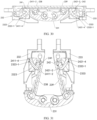
- the first rotating end of the first swing arm and the second rotating end of the second swing arm are in meshed connection through the first synchronous gear and the second synchronous gear, so that a rotation angle of the first rotating end of the first swing arm and a rotation angle of the second rotating end of the second swing arm have a same size and opposite directions, and rotation actions of the first swing arm and the second swing arm are kept synchronous relative to the main shaft, that is, the first swing arm and the second swing arm are synchronously close to or away from each other.
- the second housing 22 and the first housing 21 are disposed opposite to each other, and the second housing 22 is fastened to the foldable mechanism 23.
- the foldable mechanism 23 is provided with a second bracket 233.
- the first housing 21 is fastened to the foldable mechanism 23, and the second housing 22 is fastened to the foldable mechanism 23 for jointing carrying the display 10.
- first housing 21 and the foldable mechanism 23, and the second housing 22 and the foldable mechanism 23 are not limited to being fastened through a fastening structure, and may alternatively be fixedly mounted through welding, bonding, snap-fastening, and the like, to implement fastening of the first housing 21 and the foldable mechanism 23, and fastening of the second housing 22 and the foldable mechanism 23. In this way, in a process of unfolding or folding the foldable mechanism 23, the first housing 21 and the second housing 22 are driven to unfold or fold.
- the first bracket 232, the second bracket 233, the first swing arm 234, the second swing arm 235, the first synchronous gear 236, the second synchronous gear 237, the first moving member 241, and the second moving member 242 may jointly form a first rotating assembly.
- the foldable mechanism 23 may further include a second rotating assembly.
- the first rotating assembly and the second rotating assembly are both connected to the main shaft 231, the first door plate 238, and the second door plate 239.
- the first rotating assembly may be used as a rotating assembly at one end of the foldable mechanism 23, and the second rotating assembly may be used as a rotating assembly at the other end of the foldable mechanism 23.
- the second synchronous gear 237 includes a third tooth part 2371 and a fourth tooth part 2372.
- a radius of a tip circle of the third tooth part 2371 is different from a radius of a tip circle of the fourth tooth part 2372.
- the third tooth part 2371 is engaged with the second tooth part 2362, and the fourth tooth part 2372 is engaged with a second rotating end of the second swing arm 235.
- the tip circle is a circle in which a tip is located.
- a radius of the tip circle is a distance from the top of a tooth to a rotation center.
- the sizes of the tip circles of the two tooth parts of the first synchronous gear 236 are different, and the sizes of the tip circles of the two tooth parts of the second synchronous gear 237 are different, so that in limited space, a rotation center of the first rotating end 2341, the rotation center of the first synchronous gear 236, the rotation center of the second synchronous gear 237, and a rotation center of the second rotating end 2351 can also be properly configured, to maximize space utilization.
- the tip circle of the second tooth part 2362 and the tip circle of the third tooth part 2371 may be set to be small in size, to prevent the second tooth part 2362 and the third tooth part 2371 from pressing against the flexible display in the folded state.
- the tip circle of the first tooth part 2361 and the tip circle of the fourth tooth part 2372 may be set to be small in size, to avoid a door plate.
- FIG. 8 is a diagram of a partial exploded structure of the main shaft 231
- FIG. 9 is a diagram of the structure shown in FIG. 8 from another perspective.
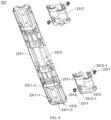
- the main shaft 231 includes an outer cover 2311 and a fastening member 2312.
- the outer cover 2311 is bent to form inner space 2313 of the main shaft 231, and the inner space 2313 is located inside the outer cover 2311.
- the fastening member 2312 can be accommodated in the inner space 2313.
- the fastening member 2312 and the fastening member 2312' fit the first rotating assembly and the second rotating assembly respectively.
- the fastening member 2312 and the fastening member 2312' may be mechanical parts independent of each other, or may be two parts of an integrated mechanical part.
- a quantity and a structural form of the fastening member are not limited in embodiments of this application. Structures of the fastening member 2312 and the fastening member 2312' may be the same or similar, symmetric or partially symmetric, or different.
- the fastening member 2312 is fastened to the outer cover 2311.
- the fastening member 2312 is provided with a first fastening hole 2312-1
- the outer cover 2311 is provided with a convex part
- the convex part is in the inner space 2313
- the convex part is provided with a second fastening hole 2311-1
- a fastener 2317 passes through the first fastening hole 2312-1 and the second fastening hole 2311-1 that are correspondingly provided to implement fastening of the fastening member 2312 and the outer cover 2311.
- the fastener 2317 may be a screw or a bolt, and a quantity of fasteners is not limited in this application, and may be set as required.
- the outer cover 2311 may be provided with a positioning post 2311-2
- the fastening member 2312 may be provided with a positioning hole 2312-2.
- the positioning post 2311-2 may first extend into the positioning hole 2312-2 to implement preliminary pre-mounting of the outer cover 2311 and the fastening member 2312, and then the outer cover 2311 and the fastening member 2312 are fastened via the fastener 2317.
- first fastening holes 2312-1, second fastening holes 2311-1, positioning holes 2312-2, and positioning posts 2311-2 are not limited, and may be disposed based on structures and space of the outer cover 2311 and the fastening member 2312.
- FIG. 8 and FIG. 9 are merely schematic structures.
- a connection manner of the fastening member 2312 and the outer cover 2311 is not limited to fastening via a fastener, and may alternatively be fixed mounting through welding, bonding, fastening connection, or the like, to implement fastening of the fastening member 2312 and the outer cover 2311.
- the fastening member 2312 and the outer cover 2311 may alternatively be of an integrated structure.
- the outer cover 2311 of the main shaft 231 includes an appearance surface 2314 that backs on the inner space 2313, and the appearance surface 2314 is an outer surface of the outer cover 2311.
- the appearance surface 2314 of the outer cover 2311 may include a first arc-shaped surface part 2314a, a planar part 2314b, and a second arc-shaped surface part 2314c, where the first arc-shaped surface part 2314a and the second arc-shaped surface part 2314c are respectively connected to two sides of the planar part 2314b.
- the appearance surface 2314 may alternatively be an arc-shaped surface or another smooth surface.
- the appearance surface 2314 of the outer cover 2311 forms a shape similar to an arc-shaped surface or an arc-shaped surface, which helps improve appearance experience and holding experience of the electronic device 100 in a folded state.
- the middle part of the appearance surface 2314 may be the planar part 2314b, so that a thickness (a size in a direction perpendicular to the planar part 2314b) of the outer cover 2311 is small, an overall thickness of the housing apparatus 20 in an unfolded state is small, and an overall width of the housing apparatus 20 in a folded state is small. This is conducive to miniaturization and thinness of the electronic device 100.
- the main shaft 231 further includes a first side 2315 and a second side 2316 that are disposed opposite to each other.
- the first side is an appearance side of the main shaft 231
- the second side 2316 is closer to the flexible display 10 than the first side 2315
- the second side 2316 is configured to carry the flexible display 10. It may be understood that the first side 2315 is an outer side of the outer cover 2311.
- the first housing 21 and the second housing 22 cover the appearance surface 2314 of the outer cover 2311.
- the first housing 21 and the second housing 22 can shield the outer cover 2311 from a back side (namely, a side back to the flexible display 10) of the housing apparatus 20.
- the first housing 21 and the second housing 22 can also shield other components of the foldable mechanism 23 from the back side of the housing apparatus 20, so that the housing apparatus 20 implements self-shielding on the back side, to protect the foldable mechanism 23.
- the housing apparatus 20 and the electronic device 100 are complete in appearance, good in appearance experience, and good in waterproof and dustproof performance.
- an appearance surface seen from the back side of the electronic device 100 is an appearance surface of the first housing 21 and the second housing 22.
- the appearance surface 2314 of the outer cover 2311 is exposed relative to the first housing 21 and the second housing 22.
- the first housing 21, the second housing 22, and the outer cover 2311 jointly form an appearance part of the electronic device 100. Therefore, the electronic device 100 can implement back-side self-shielding in the folded state. This helps improve appearance integrity, and achieves good waterproof and dustproof performance.
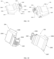
- FIG. 10A is a diagram of a structure of the fastening member 2312 of the main shaft 231
- FIG. 10B is a diagram of a structure of the fastening member 2312 shown in FIG. 10A from another perspective.
- the fastening member 2312 includes a main part 2312-3, and a first protruding part 2312-4, a second protruding part 2312-5, a third protruding part 2312-6, and a fourth protruding part 2312-7 that are located on the main part 2312-3.
- the main part 2312-3 includes a surface 2312a, where the surface 2312a is a surface that is of the main part 2312-3 and that is away from the outer cover 2311.
- the surface 2312a of the main part 2312-3 includes a first partition surface 2312a-1 and a second partition surface 2312a-2.
- the first partition surface 2312a-1 may be bent, and the second partition surface 2312a-2 may be bent.
- Both the first partition surface 2312a-1 and the second partition surface 2312a-2 may be arc-shaped surfaces.
- the first protruding part 2312-4 and the second protruding part 2312-5 may be disposed opposite to two inner side walls of the main part 2312-3, a first gap 2312b is formed between the first protruding part 2312-4 and the first partition surface 2312a-1, and a second gap 2312c is formed between the second protruding part 2312-5 and the first partition surface 2312a-1.
- the first protruding part 2312-4, the second protruding part 2312-5, and the first partition surface 2312a-1 jointly enclose first mounting space 2312-8. It may be understood that the first mounting space 2312-8 may include the first gap 2312b, the second gap 2312c, and space between the first gap 2312b and the second gap 2312c.
- the third protruding part 2312-6 and the fourth protruding part 2312-7 may be disposed opposite to two inner side walls of the main part 2312-3, a third gap 2312d is formed between the third protruding part 2312-6 and the second partition surface 2312a-2, and a fourth gap 2312e is formed between the fourth protruding part 2312-7 and the second partition surface 2312a-2.
- the third protruding part 2312-6, the fourth protruding part 2312-7, and the second partition surface 2312a-2 jointly enclose second mounting space 2312-9. It may be understood that the second mounting space 2312-9 may include the third gap 2312d, the fourth gap 2312e, and space between the third gap 2312d and the fourth gap 2312e.
- the fastening member 2312 includes a fastening part 2312f, the fastening part 2312f protrudes from an outer side wall of the main part 2312-3, and a through hole 2312g is provided on the fastening part 2312f.
- the first protruding part 2312-4, the second protruding part 2312-5, the third protruding part 2312-6, and the fourth protruding part 2312-7 may be arc-shaped structures, and the formed first gap 2312b, second gap 2312c, third gap 2312d, and fourth gap 2312e may also be arc-shaped space.
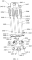
- FIG. 11 is a diagram of exploded structures of a damping assembly 243, the first synchronous gear 236, and the second synchronous gear 237
- FIG. 12A is a diagram of structures of the first synchronous gear 236 and the second synchronous gear 237
- FIG. 13 is a diagram of a structure of the assembled damping assembly 243, the first synchronous gear 236, and the second synchronous gear 237.
- the main shaft 231 includes the damping assembly 243, and the damping assembly 243 is mounted on the outer cover 2311 of the main shaft 231.
- the damping assembly 243 includes a first clamping member 2431, a second clamping member 2432, a first rotatable connecting shaft 2433, a second rotatable connecting shaft 2434, a plurality of third rotatable connecting shafts 2435, a plurality of elastic pieces 2436, and a fastening element 2437.
- the second clamping member 2432 is located between the first clamping member 2431 and the fastening element 2437, the first synchronous gear 236 and the second synchronous gear 237 are located between the first clamping member 2431 and the second clamping member 2432, the elastic piece 2436 is located between the second clamping member 2432 and the fastening element 2437, and both the first clamping member 2431 and the fastening element 2437 are fastened to the outer cover 2311.
- the first clamping member 2431 may include a first mounting hole 2431-1 and a plurality of first through holes 2431-2, and the first mounting hole 2431-1 is used for fastening the outer cover 2311.
- the plurality of first through holes 2431-2 are provided at intervals.
- the plurality of first through holes 2431-1 may be arranged in a straight line, an arc line, a wavy line, or the like. In this embodiment of this application, an example in which there are four first through holes 2431-2 is used. Extension directions of the first mounting hole 2431-1 and the first through hole 2431-2 are different.
- That a surface that is of the first clamping member 2431 and that faces the second clamping member 2432 is a smooth surface may be understood as that no protruding structure is disposed on a surface on a side that is of the first clamping member 2431 and that faces the second clamping member 2432, and the surface on the side that is of the first clamping member 2431 and that faces the second clamping member 2432 may include a plurality of parts, and each part is smooth. This helps reduce rotation resistance.
- the first clamping member 2431 further includes a body 2431-3 and a convex part 2431-4, and the convex part 2431-4 is located on a side that is of the body 2431-3 and that faces the second clamping member 2432.
- a surface that is of the body 2431-3 and that faces the second clamping member 2432 is a smooth surface
- a surface that is of the convex part 2431-4 and that faces the second clamping member 2432 is a smooth surface.
- the second clamping member 2432 includes a clamping plate 2432-1 and a plurality of bump groups 2432-2, and the plurality of bump groups 2432-2 are fastened on a same side surface of the clamping plate 2432-1 and face the first clamping member 2431.
- the clamping plate 2432-1 includes a plurality of second through holes 2432-3, and the plurality of second through holes 2432-3 are provided at intervals.
- the plurality of second through holes 2432-3 may be arranged in a straight line, an arc line, a wavy line, or the like.
- the plurality of bump groups 2432-2 are disposed in a one-to-one correspondence with the plurality of second through holes 2432-3. There may be four second through holes 2432-3 and four bump groups 2432-2.
- a quantity of second through holes 2432-3 and a quantity of bump groups 2432-2 are not limited in this application.
- Each bump group 2432-2 may include a plurality of bumps 2432-4.
- the plurality of bumps 2432-4 are arranged in an annular shape and are spaced away from each other.
- the plurality of bumps 2432-4 are disposed around the second through hole 2432-3.
- a first clamping slot 2432-5 is formed between two adjacent bumps 2432-4.
- the second clamping member 2432 may be an integrally formed mechanical part, to have high structural strength.
- the fastening element 2437 is located on a side that is of the elastic piece 2436 and that is away from the second clamping member 2432.
- the fastening element 2437 includes a second mounting hole 2437-1 and a plurality of third through holes 2437-2, and the second mounting hole 2437-1 is used for fastening the main shaft 231.
- the plurality of third through holes 2437-2 are provided at intervals, and extension directions of the second mounting hole 2437-1 and the third through holes 2437-2 are different.
- the plurality of first through holes 2431-2, the plurality of second through holes 2432-3, and the plurality of third through holes 2437-2 may be the same in quantity, arrangement shape, and arrangement spacing.
- the elastic piece 2436 is located on a side that is of the second clamping member 2432 and that is away from the first clamping member 2431.
- the elastic piece 2436 may include a plurality of springs 2436-1.
- a quantity of springs 2436-1 is the same as a quantity of first through holes 2431-2.
- the elastic piece 2436 may alternatively be of an elastic material like an elastic rubber. This is not strictly limited in this application.
- a limiting flange 2433-1 is disposed at a top end of the first rotatable connecting shaft 2433, and an outer diameter of the limiting flange 2433-1 is greater than an outer diameter of a main body part of the first rotatable connecting shaft 2433.
- a limiting clamping slot 2433-2 is provided at a bottom end of the first rotatable connecting shaft 2433, the limiting clamping slot 2433-2 shrinks inward relative to an outer surface of the main body part of the first rotatable connecting shaft 2433, and a diameter of a slot bottom wall of the limiting clamping slot 2433-2 is less than an outer diameter of the main body part of the first rotatable connecting shaft 2433.
- the first rotatable connecting shaft 2433 is inserted with the first clamping member 2431, the second clamping member 2432, one of the springs 2436-1, and the fastening element 2437.
- the first rotatable connecting shaft 2433 passes through one of the first through holes 2431-2 of the first clamping member 2431, one of the second through holes 2432-3 of the second clamping member 2432, inner space of one of the springs 2436-1, and one of the third through holes 2437-2 of the fastening element 2437.
- the limiting flange 2433-1 of the first rotatable connecting shaft 2433 is located on a side that is of the first clamping member 2431 and that is away from the second clamping member 2432 and presses against the first clamping member 2431, and the fastening element 2437 is clamped into the limiting clamping slot 2433-2 of the first rotatable connecting shaft 2433, so that the first clamping member 2431, the second clamping member 2432, one of the springs 2436-1, and the fastening element 2437 may maintain a fixed position relationship, and the spring 2436-1 is in a compressed state.
- a bottom end of the first rotatable connecting shaft 2433 may be further fastened to the fastening element 2437 through welding, bonding, or the like.
- a limiting flange 2434-1 is disposed at a top end of the second rotatable connecting shaft 2434, and an outer diameter of the limiting flange 2434-1 is greater than an outer diameter of a main body part of the second rotatable connecting shaft 2434.
- a limiting clamping slot 2434-2 is provided at a bottom end of the second rotatable connecting shaft 2434, the limiting clamping slot 2434-2 shrinks inward relative to an outer surface of the main body part of the second rotatable connecting shaft 2434, and a diameter of a slot bottom wall of the limiting clamping slot 2434-2 is less than an outer diameter of the main body part of the second rotatable connecting shaft 2434.
- the second rotatable connecting shaft 2434 and the first rotatable connecting shaft 2433 may be the same in structure, and are of a same material, so that material types are reduced, and costs are reduced.
- a structure of the second rotatable connecting shaft 2434 may alternatively be different from a structure of the first rotatable connecting shaft 2433. This is not strictly limited in this application.
- the second rotatable connecting shaft 2434 is inserted with the first clamping member 2431, the second clamping member 2432, one of the springs 2436-1, and the fastening element 2437.
- the second rotatable connecting shaft 2434 passes through one of the first through holes 2431-2 of the first clamping member 2431, one of the second through holes 2432-3 of the second clamping member 2432, inner space of one of the springs 2436-1, and one of the third through holes 2437-2 of the fastening element 2437.
- the limiting flange 2434-1 of the second rotatable connecting shaft 2434 is located on a side that is of the first clamping member 2431 and that is away from the second clamping member 2432 and presses against the first clamping member 2431, and the fastening element 2437 is clamped into the limiting clamping slot 2434-2 of the second rotatable connecting shaft 2434, so that the first clamping member 2431, the second clamping member 2432, one of the springs 2436-1, and the fastening element 2437 may maintain a fixed position relationship, and the spring 2436-1 is in a compressed state.
- a bottom end of the second rotatable connecting shaft 2434 may be further fastened to the fastening element 2437 through welding, bonding, or the like.
- a limiting flange 2435-1 is disposed at a top end of the third rotatable connecting shaft 2435, and an outer diameter of the limiting flange 2435-1 is greater than an outer diameter of a main body part of the third rotatable connecting shaft 2435.
- a limiting clamping slot 2435-2 is provided at a bottom end of the third rotatable connecting shaft 2435, the limiting clamping slot 2435-2 shrinks inward relative to an outer surface of the main body part of the third rotatable connecting shaft 2435, and a diameter of a slot bottom wall of the limiting clamping slot 2435-2 is less than an outer diameter of the main body part of the third rotatable connecting shaft 2435.
- the third rotatable connecting shaft 2435 and the first rotatable connecting shaft 2433 may be the same in structure, and are of a same material, so that material types are reduced, and costs are reduced.
- a structure of the third rotatable connecting shaft 2435 may alternatively be different from a structure of the first rotatable connecting shaft 2433. This is not strictly limited in this application.
- a quantity of third rotatable connecting shafts 2435 is the same as a quantity of synchronous gears (including the first synchronous gear 236 and the second synchronous gear 237, and more other synchronous gears), and the third rotatable connecting shafts 2435, the synchronous gears, and some springs 2436-1 in the elastic piece 2436 are disposed in a one-to-one correspondence.
- the third rotatable connecting shaft 2435 is inserted with the first clamping member 2431, one of the synchronous gears, the second clamping member 2432, one of the springs 2436-1, and the fastening element 2437.
- the third rotatable connecting shaft 2435 passes through one of the first through holes 2431-2 of the first clamping member 2431, one of the second through holes 2432-3 of the second clamping member 2432, a rotating shaft hole of the first synchronous gear 236 (or a rotating shaft hole of the second synchronous gear 237, or a rotating shaft hole of another synchronous gear, where one third rotatable connecting shaft 2435 corresponds to one synchronous gear), inner space of one of the springs 2436-1 and one of the third through holes 2437-2 of the fastening element 2437.
- the limiting flange 2435-1 of the third rotatable connecting shaft 2435 is located on a side that is of the first clamping member 2431 and that is away from the second clamping member 2432 and presses against the first clamping member 2431, and the fastening element 2437 is clamped into the limiting clamping slot 2435-2 of the third rotatable connecting shaft 2435, so that the first clamping member 2431, the second clamping member 2432, the synchronous gear, one of the springs 2436-1, and the fastening element 2437 may maintain a fixed position relationship, and the spring 2436-1 is in a compressed state.
- a bottom end of the third rotatable connecting shaft 2435 may be further fastened to the fastening element 2437 through welding, bonding, or the like.
- the first synchronous gear 236 and the second synchronous gear 237 are located between the first clamping member 2431 and the second clamping member 2432.
- the first synchronous gear 236 and the second synchronous gear 237 are engaged with each other.
- a radius R1 of a tip circle of the first tooth part 2361 of the first synchronous gear 236 is different from a radius R2 of a tip circle of the second tooth part 2362 of the first synchronous gear 236, and the second tooth part 2362 is engaged with the second synchronous gear 237.
- the radius R1 of the tip circle of the first tooth part 2361 may be greater than the radius R2 of the tip circle of the second tooth part 2362.
- the radius R1 of the tip circle of the first tooth part 2361 of the first synchronous gear 236 is used as an example.
- the radius R1 of the tip circle of the first tooth part 2361 is a distance from a top of the first tooth part 2361 to a rotation center of the first tooth part 2361.
- a radius R3 of a tip circle of the third tooth part 2371 of the second synchronous gear 237 is different from a radius R4 of a tip circle of the fourth tooth part 2372, and the third tooth part 2371 is engaged with the second tooth part 2362.
- a radius R4 of a tip circle of the fourth tooth part 2372 may be greater than the radius R3 of the tip circle of the third tooth part 2371.
- the radius R1 of the tip circle of the first tooth part 2361 is less than the radius R2 of the tip circle of the second tooth part 2362, and the radius R4 of the tip circle of the fourth tooth part 2372 is less than the radius R3 of the tip circle of the third tooth part 2371.
- FIG. 12B is a diagram of structures of the first synchronous gear 236 and the second synchronous gear 237, and structures in FIG. 12A and FIG. 12B are the same, and are only for ease of identification.
- a radius R11 of an indexing circle of the first tooth part 2361 of the first synchronous gear 236 is different from a radius R12 of an indexing circle of the second tooth part 2362
- a radius R13 of an indexing circle of the third tooth part 2371 of the second synchronous gear 237 is different from a radius R14 of an indexing circle of the fourth tooth part 2372.
- the indexing circle is a product of a modulus and a number of teeth.
- the modulus is a basic parameter for calculating a geometric dimension of the gear.
- a size of the modulus indicates a thickness, a size, and a bearing capability of the gear. When the size of the tip circle changes, the size of the indexing circle changes accordingly.
- the first synchronous gear 236 further includes a first rotating shaft hole 2363 and a plurality of first protrusions 2364.
- the plurality of first protrusions 2364 are located at an end of the first synchronous gear 236 and are disposed around the first rotating shaft hole 2363, and the plurality of first protrusions 2364 are arranged in an annular shape, are spaced from each other, and are disposed facing the second clamping member 2432.
- One third rotatable connecting shaft 2435 is inserted into the first rotating shaft hole 2363 of the first synchronous gear 236, to implement a rotatable connection between the first synchronous gear 236 and the main shaft 231.
- Another third rotatable connecting shaft 2435 is inserted into the second rotating shaft hole 2373 of the second synchronous gear 237, to implement a rotatable connection between the second synchronous gear 237 and the main shaft 231.
- one first protrusion 2364 of the first synchronous gear 236 and a plurality of bumps 2432-4 of the second clamping member 2432 are arranged in a staggered manner to form a clamping structure, and the plurality of first protrusions 2364 are correspondingly clamped into the plurality of first clamping slots 2432-5.
- Shapes and positions of the plurality of first protrusions 2364 of the first synchronous gear 236 adapt to shapes and positions of the corresponding plurality of first clamping slots 2432-5.
- One second protrusion 2374 of the second synchronous gear 237 and the plurality of bumps 2432-4 of the second clamping member 2432 are arranged in a staggered manner to form a clamping structure, and the plurality of second protrusions 2374 are correspondingly clamped into the plurality of first clamping slots 2432-5.
- Shapes and positions of the plurality of second protrusions 2374 of the second synchronous gear 237 adapt to shapes and positions of the corresponding plurality of first clamping slots 2432-5.
- the first synchronous gear 236 may be an integrally formed mechanical part, to have high structural strength.
- the second synchronous gear 237 may be an integrally formed mechanical part, to have high structural strength.
- the first synchronous gear 236 and the second synchronous gear 237 may be the same in structure, and are of a same material, so that material types are reduced, and costs are reduced. In some other embodiments, structures of the first synchronous gear 236 and the second synchronous gear 237 may be different. This is not strictly limited in this application.
- damping assembly 243 in this application may have a plurality of implementation structures.
- the foregoing is merely a structure of the damping assembly 243 in an implementation.
- a specific structure of the damping assembly 243 is not limited in this application.
- FIG. 14 is a diagram of a partial structure of the main shaft 231, and the fastening member 2312, the damping assembly 243, and a part of the outer cover 2311 are included in FIG. 14 .
- the fastening member 2312 of the main shaft 231 is mounted on the outer cover 2311, and the damping assembly 243 is mounted on the outer cover 2311.
- the fastening member 2312 is fastened to the outer cover 2311 via the fastener 2317.
- the damping assembly 243 is mounted on the outer cover 2311, a first mounting hole 2431-1 of the first clamping member 2431 of the damping assembly 243 is provided corresponding to a through hole 2312g of the fastening member 2312, and the fastener passes through the first mounting hole 2431-1 and the through hole 2312g of the fastening member 2312, to implement fastening of the damping assembly 243 and the fastening member 2312.
- both the first clamping member 2431 and the fastening element 2437 are fastened to the outer cover 2311.
- only the second clamping member 2432 moves, and neither the first clamping member 2431 nor the fastening element 2437 moves, so that a damping mechanism in this implementation of this application is stable.
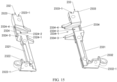
- FIG. 15 is a diagram of structures of the first bracket 232 and the second bracket 233
- FIG. 16 is a diagram of structures of the first bracket 232 and the second bracket 233 shown in FIG. 15 from another perspective.
- the first bracket 232 includes a first body 2321, and a first mounting part 2322, a second mounting part 2323, and a third mounting part 2324 that are located on the first body 2321.
- the first mounting part 2322 and the second mounting part 2323 are respectively located at two opposite ends of the first body 2321, and the third mounting part 2324 is located between the first mounting part 2322 and the second mounting part 2323.
- the first mounting part 2322 protrudes from the first body 2321, the first mounting part 2322 includes a first fitting part 2322-1 and a first arc-shaped bar 2322-2, and the first arc-shaped bar 2322-2 is located on a side that is of the first fitting part 2322-1 and that faces the third mounting part 2324.
- the first arc-shaped bar 2322-2 is an arc-shaped bar structure.
- the second mounting part 2323 includes a first arc-shaped slot 2323-1, the first arc-shaped slot 2323-1 includes an opening and a bottom wall that are disposed opposite to each other, and the opening and the bottom wall of the first arc-shaped slot 2323-1 extend in a direction in which the first mounting part 2322, the second mounting part 2323, and the third mounting part 2324 are arranged.
- the third mounting part 2324 includes a first sliding groove 2324-1.
- the first sliding groove 2324-1 includes a first main slot 2324-2, and a first side slot 2324-3 and a second side slot 2324-4 that are provided at two ends of the first main slot 2324-2.
- the first main slot 2324-2, the first side slot 2324-3, and the second side slot 2324-4 communicate with each other.
- the second bracket 233 includes a second body 2331, and a fourth mounting part 2332, a fifth mounting part 2333, and a sixth mounting part 2334 that are located on the second body 2331.
- the fourth mounting part 2332 and the fifth mounting part 2333 are respectively located at two opposite ends of the second body 2331, and the sixth mounting part 2334 is located between the fourth mounting part 2332 and the fifth mounting part 2333.
- the fourth mounting part 2332 protrudes from the second body 2331, the fourth mounting part 2332 includes a second fitting part 2332-1 and a second arc-shaped bar 2332-2, and the second arc-shaped bar 2332-2 is located on a side that is of the second fitting part 2332-1 and that faces the sixth mounting part 2334.
- the second arc-shaped bar 2332-2 is an arc-shaped bar structure.
- the fifth mounting part 2333 includes a second arc-shaped slot 2333-1, the second arc-shaped slot 2333-1 includes an opening and a bottom wall that are disposed opposite to each other, and the opening and the bottom wall of the second arc-shaped slot 2333-1 extend in a direction in which the fourth mounting part 2332, the fifth mounting part 2333, and the sixth mounting part 2334 are arranged.
- the sixth mounting part 2334 includes a second sliding groove 2334-1.
- the second sliding groove 2334-1 includes a second main slot 2334-2, and a third side slot 2334-3 and a fourth side slot 2334-4 that are provided at two ends of the second main slot 2334-2.
- the second main slot 2334-2, the third side slot 2334-3, and the fourth side slot 2334-4 communicate with each other.
- FIG. 17 is a diagram of structures of the first moving member 241 and the second moving member 242
- FIG. 18 is a diagram of structures of the first moving member 241 and the second moving member 242 shown in FIG. 17 from another perspective.
- the first moving member 241 includes a first connection part 2411, a first connection arm 2412, and a first arc-shaped arm 2413, and the first connection arm 2412 is fastened between the first connection part 2411 and the first arc-shaped arm 2413.
- the first connection part 2411 includes a first end 2411-1 and a second end 2411-2 that are disposed opposite to each other, the first end 2411-1 is provided with a third arc-shaped slot 2411-3, and the second end 2411-2 is provided with a third arc-shaped bar 2411-4.
- the second end 2411-2 further includes a first assembly hole 2411-5.
- the first arc-shaped arm 2413 includes a first main arc arm 2413-1, and a fourth arc-shaped bar 2413-2 and a fifth arc-shaped bar 2413-3 that are located on two opposite sides of the first main arc arm 2413-1.
- the first main arc arm 2413-1 further includes a first groove 2413-4, a second assembly hole 2413-5, and a first limiting post 2413-6.
- the first groove 2413-4 is provided opposite to the first connection part 2411.
- the second moving member 242 includes a second connection part 2421, a second connection arm 2422, and a second arc-shaped arm 2423, and the second connection arm 2422 is fastened between the second connection part 2421 and the second arc-shaped arm 2423.
- the second connection part 2421 includes a third end 2421-1 and a fourth end 2421-2 that are disposed opposite to each other, the third end 2421-1 is provided with a fourth arc-shaped slot 2421-3, and the fourth end 2421-2 is provided with a sixth arc-shaped bar 2421-4.
- the fourth end 2421-2 further includes a third assembly hole 2421-5
- the second arc-shaped arm 2423 includes a second main arc arm 2423-1, and a seventh arc-shaped bar 2423-2 and an eighth arc-shaped bar 2423-3 that are located on two opposite sides of the second main arc arm 2423-1.
- the second main arc arm 2423-1 further includes a second groove 2423-4, a fourth assembly hole 2423-5, and a second limiting post 2423-6.
- the second groove 2423-4 is provided opposite to the first connection part 2411.
- FIG. 19 is a diagram of structures of the first swing arm 234 and the second swing arm 235
- FIG. 20 is a diagram of structures of the first swing arm 234 and the second swing arm 235 shown in FIG. 19 from another perspective.
- the first swing arm 234 includes a first rotating end 2341 and a first sliding end 2342
- the first rotating end 2341 includes a third rotating shaft hole 2343, a fifth tooth part 2344, and a plurality of third protrusions 2345
- the fifth tooth part 2344 surrounds the third rotating shaft hole 2343
- the plurality of third protrusions 2345 surround the third rotating shaft hole 2343 and are located on a side of the fifth tooth part 2344.
- a side of the first rotating end 2341 includes a first pressing part 2341-1 and a second pressing part 2341-2, and the second pressing part 2341-2 protrudes from the first pressing part 2341-1.
- the first sliding end 2342 includes a first main sliding part 2346, and a first side part 2347 and a second side part 2348 that are located on two opposite sides of the first main sliding part 2346, and the first main sliding part 2346 is fastened to the first rotating end 2341.
- the first swing arm 234 may be an integrally formed mechanical part, to have high structural strength.
- the second swing arm 235 includes a second rotating end 2351 and a second sliding end 2352.
- the second rotating end 2351 includes a fourth rotating shaft hole 2353, a sixth tooth part 2354, and a plurality of fourth protrusions 2355, where the sixth tooth part 2354 surrounds the fourth rotating shaft hole 2353, and the plurality of fourth protrusions 2355 surround the fourth rotating shaft hole 2353 and are located on a side of the sixth tooth part 2354.
- a side of the second rotating end 2351 includes a third pressing part 2351-1 and a fourth pressing part 2351-2, and the fourth pressing part 2351-2 protrudes from the third pressing part 2351-1.
- the second sliding end 2352 includes a second main sliding part 2356, and a third side part 2357 and a fourth side part 2358 that are located on two opposite sides of the second main sliding part 2356.
- the second main sliding part 2356 is fastened to the second rotating end 2351.
- the second swing arm 235 may be an integrally formed mechanical part, to have high structural strength.
- the first swing arm 234 and the second swing arm 235 may be the same in structure, and are of a same material, so that material types are reduced, and costs are reduced. In some other embodiments, structures of the first swing arm 234 and the second swing arm 235 may be different. This is not strictly limited in this application.
- FIG. 21 is a diagram of a structure in which the first swing arm 234 and the second swing arm 235 are assembled to the damping assembly 243.
- the first rotatable connecting shaft 2433 of the damping assembly 243 passes through the third rotating shaft hole 2343 of the first rotating end 2341 of the first swing arm 234, and the first rotating end 2341 of the first swing arm 234 is rotatably connected to the main shaft 231.
- the second rotatable connecting shaft 2434 of the damping assembly 243 passes through the fourth rotating shaft hole 2353 of the second rotating end 2351 of the second swing arm 235, and the second rotating end 2351 of the second swing arm 235 is rotatably connected to the main shaft 231.
- the third rotating shaft hole 2343 of the first swing arm 234, the first rotating shaft hole 2363 of the first synchronous gear 236, the second rotating shaft hole 2373 of the second synchronous gear 237, and the fourth rotating shaft hole 2353 of the second swing arm 235 are arranged in an arc shape, so that space of the main shaft 231 can be fully utilized, and more internal space of the main shaft 231 can be released to accommodate the flexible display. This helps improve compactness of arrangement of mechanical parts of the electronic device 100, reduce a volume of the electronic device 100, and facilitate miniaturization and thinness of the electronic device 100.
- one third protrusion 2345 of the first swing arm 234 and a plurality of bumps 2432-4 of the second clamping member 2432 are arranged in a staggered manner to form a clamping structure, and the plurality of third protrusions 2345 are correspondingly clamped into the plurality of first clamping slots 2432-5.
- Shapes and positions of the plurality of third protrusions 2345 of the first swing arm 234 adapt to shapes and positions of the corresponding plurality of first clamping slots 2432-5.
- One fourth protrusion 2355 of the second swing arm 235 and the plurality of bumps 2432-4 of the second clamping member 2432 are arranged in a staggered manner to form a clamping structure, and the plurality of fourth protrusions 2355 are correspondingly clamped into the plurality of first clamping slots 2432-5.
- Shapes and positions of the plurality of fourth protrusions 2355 of the second swing arm 235 adapt to shapes and positions of the corresponding plurality of first clamping slots 2432-5.
- the elastic piece 2436 is compressed between the second clamping member 2432 and the fastening element 2437. Elastic force generated by the elastic piece 2436 drives the second clamping member 2432 to press the first swing arm 234, the second swing arm 235, the first synchronous gear 236, and the second synchronous gear 237.
- a clamping structure between the second clamping member 2432, and the first swing arm 234, the second swing arm 235, the first synchronous gear 236, and the second synchronous gear 237 is used, so that the first swing arm 234, the second swing arm 235, the first synchronous gear 236, and the second synchronous gear 237 can stay at some positions.
- the first swing arm 234 moves relative to the second swing arm 235
- the first rotating end 2341 of the first swing arm 234, the second rotating end 2351 of the second swing arm 235, the first synchronous gear 236, the second synchronous gear 237, the first clamping member 2431, and the second clamping member 2432 need to be switched from one clamping structure to another clamping structure.
- the second clamping member 2432 is away from the first clamping member 2431
- the elastic piece 2436 is further compressed, and elastic force generated by the elastic piece 2436 forms motion damping force, so that the first swing arm 234 and the second swing arm 235 need to move relative to each other with specific driving force.
- the clamping structure between the second clamping member 2432, and the first swing arm 234, the second swing arm 235, the first synchronous gear 236, and the second synchronous gear 237 can provide motion damping force for relative motion of the first swing arm 234 and the second swing arm 235.
- the second pressing part 2341-2 of the first rotating end 2341 presses against the body 2431-3 of the first clamping member 2431
- a part of the first pressing part 2341-1 presses against the convex part 2431-4 of the first clamping member 2431
- a gap 244 exists between another part of the first pressing part 2341-1 and the body 2431-3 of the first clamping member 2431.
- a gap exists between the first clamping member 2431 and a partial structure that is of the first rotating end 2341 and that faces the first clamping member 2431, so that a contact area can be reduced, and friction can be reduced.
- An area of contact between the end that is of the first rotating end 2341 and that faces the first clamping member 2431 and the first clamping member 2431 is excessively small, and consequently, there is no touch feeling during folding or unfolding.
- An area of contact between the end that is of the first rotating end 2341 and that faces the first clamping member 2431 and the first clamping member 2431 is excessively large, and consequently, folding or unfolding is uneasy.
- the area of contact between the end that is of the first rotating end 2341 and that faces the first clamping member 2431 and the first clamping member 2431 may be adjusted, to control a touch feeling of folding or unfolding the electronic device 100.
- FIG. 22 is a diagram of exploded structures of the first bracket 232, the second bracket 233, the first moving member 241, the second moving member 242, the first swing arm 234, and the second swing arm 235.
- the first bracket 232 is rotatably connected to the first moving member 241.
- the first mounting part 2322 of the first bracket 232 is rotatably connected to the first end 2411-1 of the first connection part 2411 of the first moving member 241, and the first arc-shaped bar 2322-2 of the first mounting part 2322 is located in the third arc-shaped slot 2411-3 of the first end 2411-1.
- the first arc-shaped bar 2322-2 of the first mounting part 2322 fits the third arc-shaped slot 2411-3 of the first end 2411-1 and can move in the third arc-shaped slot 2411-3 of the first end 2411-1, to implement a rotatable connection between the first bracket 232 and the first moving member 241. It may be understood that a radian of the first arc-shaped bar 2322-2 of the first mounting part 2322 may be consistent with a radian of the third arc-shaped slot 2411-3 of the first end 2411-1.
- the second mounting part 2323 of the first bracket 232 is rotatably connected to the second end 2411-2 of the first connection part 2411 of the first moving member 241, the third arc-shaped bar 2411-4 at the second end 2411-2 is located in the first arc-shaped slot 2323-1 of the second mounting part 2323, and the third arc-shaped bar 2411-4 at the second end 2411-2 fits the first arc-shaped slot 2323-1 of the second mounting part 2323 and can move in the first arc-shaped slot 2323-1 of the second mounting part 2323, to implement a rotatable connection between the first bracket 232 and the first moving member 241. It may be understood that a radian of the third arc-shaped bar 2411-4 at the second end 2411-2 may be consistent with a radian of the first arc-shaped slot 2323-1 of the second mounting part 2323.
- the second bracket 233 is rotatably connected to the second moving member 242.
- the fourth mounting part 2332 of the second bracket 233 is rotatably connected to the third end 2421-1 of the second connection part 2421 of the second moving member 242, and the second arc-shaped bar 2332-2 of the fourth mounting part 2332 is located in the fourth arc-shaped slot 2421-3 of the third end 2421-1.
- the second arc-shaped bar 2332-2 of the fourth mounting part 2332 fits the fourth arc-shaped slot 2421-3 of the third end 2421-1 and can move in the fourth arc-shaped slot 2421-3 of the third end 2421-1, to implement a rotatable connection between the second bracket 233 and the second moving member 242. It may be understood that a radian of the second arc-shaped bar 2332-2 of the fourth mounting part 2332 may be consistent with a radian of the fourth arc-shaped slot 2421-3 of the third end 2421-1.
- the fifth mounting part 2333 of the second bracket 233 is rotatably connected to the fourth end 2421-2 of the second connection part 2421 of the second moving member 242, the sixth arc-shaped bar 2421-4 at the fourth end 2421-2 is located in the second arc-shaped slot 2333-1 of the fifth mounting part 2333, and the sixth arc-shaped bar 2421-4 at the fourth end 2421-2 fits the second arc-shaped slot 2333-1 of the fifth mounting part 2333 and can move in the second arc-shaped slot 2333-1 of the fifth mounting part 2333, to implement a rotatable connection between the second bracket 233 and the second moving member 242. It may be understood that a radian of the sixth arc-shaped bar 2421-4 of the fourth end 2421-2 may be consistent with a radian of the second arc-shaped slot 2333-1 of the fifth mounting part 2333.
- the foregoing only provides a rotatable connection manner between the first bracket 232 and the first moving member 241, and a ratable connection manner between the second bracket 233 and the second moving member 242.
- the first bracket 232 and the first moving member 241, and the second bracket 233 and the second moving member 242 may also be rotatably connected in a form of a physical shaft via a rotating shaft.
- the first sliding end 2342 of the first swing arm 234 is slidably connected to the third mounting part 2324 of the first bracket 232.
- the first main sliding part 2346 of the first sliding end 2342 is disposed corresponding to the first main slot 2324-2 of the third mounting part 2324
- the first side part 2347 of the first sliding end 2342 is clamped into the first side slot 2324-3 of the third mounting part 2324
- the second side part 2348 of the first sliding end 2342 is clamped into the second side slot 2324-4 of the third mounting part 2324
- the first sliding end 2342 can slide in the third mounting part 2324, to implement a slidable connection between the first swing arm 234 and the first bracket 232.
- the second sliding end 2352 of the second swing arm 235 is slidably connected to the sixth mounting part 2334 of the second bracket 233.
- the second main sliding part 2356 of the second sliding end 2352 is disposed corresponding to the second main slot 2334-2 of the sixth mounting part 2334
- the third side part 2357 of the second sliding end 2352 is clamped into the third side slot 2334-3 of the sixth mounting part 2334
- the fourth side part 2358 of the second sliding end 2352 is clamped into the fourth side slot 2334-4 of the sixth mounting part 2334
- the second sliding end 2352 can slide in the sixth mounting part 2334, to implement a slidable connection between the second swing arm 235 and the second bracket 233.
- a sliding groove may alternatively be provided at the first sliding end 2342 of the first swing arm 234, a sliding structure may be disposed at the third mounting part 2324 of the first bracket 232, and the sliding structure of the third mounting part 2324 fits the sliding groove of the first swing arm 234 to implement a slidable connection between the first swing arm 234 and the first bracket 232.
- a sliding groove may be provided at the second sliding end 2352 of the second swing arm 235, a sliding structure may be disposed at the sixth mounting part 2334 of the second bracket 233, and the sliding structure of the sixth mounting part 2334 fits the sliding groove of the second swing arm 235 to implement a slidable connection between the second swing arm 235 and the second bracket 233.
- a slidable connection manner between the first swing arm 234 and the first bracket 232 and a slidable connection manner between the second swing arm 235 and the second bracket 233 are not described in this application.
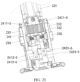
- FIG. 23 is a diagram of a partial structure of the foldable mechanism 23.
- the first moving member 241 is rotatably connected to the main shaft 231, so that the first bracket 232 is connected to the main shaft 231.
- the first arc-shaped arm 2413 of the first moving member 241 is rotatably connected to the first mounting space 2312-8 of the fastening member 2312 of the main shaft 231.
- the fourth arc-shaped bar 2413-2 of the first arc-shaped arm 2413 is clamped into a second gap 2312c of the first mounting space 2312-8, and the second gap 2312c may be arc-shaped space, and is configured to fit the fourth arc-shaped bar 2413-2, to implement a rotatable connection between the first moving member 241 and the main shaft 231.
- the fifth arc-shaped bar 2413-3 of the first arc-shaped arm 2413 is clamped into the first gap 2312b of the first mounting space 2312-8, and the first gap 2312b may be arc-shaped space, and is configured to fit the fifth arc-shaped bar 2413-3, to implement a rotatable connection between the first moving member 241 and the main shaft 231.
- the first main arc arm 2413-1 of the first arc-shaped arm 2413 is located in space between the first gap 2312b and the second gap 2312c.
- the first arc-shaped arm 2413 can rotate in the first mounting space 2312-8, to implement a rotatable connection between the first moving member 241 and the main shaft 231.
- the first moving member 241 fits the main shaft 231 to form a rotatable connection structure using a virtual shaft. This can reduce design difficulty of the foldable mechanism 23, has a low requirement on a size of the foldable mechanism 23, and facilitates lightness and thinness of the foldable mechanism 23.
- the first moving member 241 and the main shaft 231 may alternatively be rotatably connected by using a physical shaft. This is not strictly limited in embodiments of this application.
- the second moving member 242 is rotatably connected to the main shaft 231, so that the second bracket 233 is connected to the main shaft 231.
- the second arc-shaped arm 2423 of the second moving member 242 is rotatably connected to the second mounting space 2312-9 of the fastening member 2312 of the main shaft 231.
- the seventh arc-shaped bar 2423-2 of the second arc-shaped arm 2423 is clamped into a fourth gap 2312e of the second mounting space 2312-9, and the fourth gap 2312e may be arc-shaped space, and is configured to fit the seventh arc-shaped bar 2423-2, to implement a rotatable connection between the second moving member 242 and the main shaft 231.
- the eighth arc-shaped bar 2423-3 of the second arc-shaped arm 2423 is clamped into a third gap 2312d of the second mounting space 2312-9, and the third gap 2312d may be arc-shaped space, and is configured to fit the eighth arc-shaped bar 2423-3, to implement a rotatable connection between the second moving member 242 and the main shaft 231.
- the second main arc arm 2423-1 of the second arc-shaped arm 2423 is located in space between the third gap 2312d and the fourth gap 2312e, and the second arc-shaped arm 2423 can rotate in the second mounting space 2312-9, to implement a rotatable connection between the second moving member 242 and the main shaft 231.
- the second moving member 242 fits the main shaft 231 to form a rotatable connection structure using a virtual shaft. This can reduce design difficulty of the foldable mechanism 23, has a low requirement on a size of the foldable mechanism 23, and facilitates lightness and thinness of the foldable mechanism 23.
- the second moving member 242 and the main shaft 231 may alternatively be rotatably connected by using a physical shaft. This is not strictly limited in embodiments of this application.
- FIG. 24 is a diagram of structures of the first door plate 238 and the second door plate 239.
- the first door plate 238 and the second door plate 239 are located on the second side 2316 of the main shaft 231.
- the first door plate 238 is of a plate-like structure.
- the first door plate 238 includes a first limiting hole 2382, a fifth assembly hole 2383, a sixth assembly hole 2384, a first plate edge 2385, and a second plate edge 2386.
- the first plate edge 2385 and the second plate edge 2386 are disposed opposite to each other.
- the first limiting hole 2382, the fifth assembly hole 2383, and the sixth assembly hole 2384 are located between the first plate edge 2385 and the second plate edge 2386.
- Positions and quantities of first limiting holes 2382, fifth assembly holes 2383, and sixth assembly holes 2384 on the first door plate 238 may be set according to a requirement. This is not limited in this application.
- the second door plate 239 includes a second limiting hole 2392, a seventh assembly hole 2393, an eighth assembly hole 2394, a third plate edge 2395, and a fourth plate edge 2396.
- the third plate edge 2395 and the fourth plate edge 2396 are disposed opposite to each other.
- the second limiting hole 2392, the seventh assembly hole 2393, and the eighth assembly hole 2394 are located between the third plate edge 2395 and the fourth plate edge 2396.
- Positions and quantities of second limiting holes 2392, seventh assembly holes 2393, and eighth assembly holes 2394 on the second door plate 239 may be set according to a requirement. This is not limited in this application.
- the first door plate 238 is fastened to the first moving member 241.
- the first limiting post 2413-6 of the first moving member 241 passes through the first limiting hole 2382 of the first door plate 238, to implement preliminary positioning and mounting of the first door plate 238 and the first moving member 241.
- the fifth assembly hole 2383 of the first door plate 238 is provided corresponding to the second assembly hole 2413-5 of the first moving member 241, and a fastener (not shown in FIG. 23 and FIG. 24 ) passes through the fifth assembly hole 2383 and the second assembly hole 2413-5 for fastening.
- the sixth assembly hole 2384 of the first door plate 238 is provided corresponding to the first assembly hole 2411-5 of the first moving member 241, and a fastener (not shown in FIG. 23 and FIG. 24 ) passes through the sixth assembly hole 2384 and the first assembly hole 2411-5, to fasten the first door plate 238 and the first moving member 241.
- the second door plate 239 is fastened to the second moving member 242.
- the second limiting post 2423-6 of the second moving member 242 passes through the second limiting hole 2392 of the second door plate 239, to implement preliminary positioning and mounting of the second door plate 239 and the second moving member 242.
- the seventh assembly hole 2393 of the second door plate 239 is provided corresponding to the fourth assembly hole 2423-5 of the second moving member 242, and a fastener (not shown in FIG. 23 and FIG. 24 ) passes through the seventh assembly hole 2393 and the fourth assembly hole 2423-5 for fastening.
- the eighth assembly hole 2394 of the second door plate 239 is provided corresponding to the third assembly hole 2421-5 of the second moving member 242, and a fastener (not shown in FIG. 23 and FIG. 24 ) passes through the eighth assembly hole 2394 and the third assembly hole 2421-5, to fasten the second door plate 239 and the second moving member 242.
- FIG. 25 is a diagram of a structure of the foldable mechanism 23 shown in FIG. 7 in a folded state.
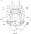
- FIG. 26 is a diagram of a structure of the assembled foldable mechanism 23 shown in FIG. 25 and the flexible display 10.
- the first rotating end 2341 of the first swing arm 234 is engaged with the first tooth part 2361 of the first synchronous gear 236, and the second rotating end 2351 of the second swing arm 235 is engaged with the fourth tooth part 2372 of the second synchronous gear 237.
- the second tooth part 2362 of the first synchronous gear 236 is engaged with the third tooth part 2371 of the second synchronous gear 237.
- the first rotating end 2341 of the first swing arm 234 and the second rotating end 2351 of the second swing arm 235 are connected through the first synchronous gear 236 and the second synchronous gear 237, so that a rotation angle of the first rotating end 2341 of the first swing arm 234 and a rotation angle of the second rotating end 2351 of the second swing arm 235 have a same size and opposite directions, and rotation actions of the first swing arm 234 and the second swing arm 235 are kept synchronous relative to the main shaft 231, that is, the first swing arm 234 and the second swing arm 235 are synchronously close to or away from each other.
- first sliding end 2342 of the first swing arm 234 is slidably connected to the first bracket 232
- second sliding end 2352 of the second swing arm 235 is slidably connected to the second bracket 233
- first swing arm 234 affects a rotation angle of the first bracket 232
- second swing arm 235 affects a rotation angle of the second bracket 233, so that rotation actions of the first bracket 232 and the second bracket 233 relative to the main shaft 231 are kept synchronous, that is, the first bracket 232 and the second bracket 233 are synchronously close to each other or away from each other, to improve mechanism operation experience of the housing apparatus 20 and the electronic device 100.
- a radius R1 of a tip circle of the first tooth part 2361 may be greater than a radius R2 of a tip circle of the second tooth part 2362, and a radius R4 of a tip circle of the fourth tooth part 2372 may be greater than a radius R3 of a tip circle of the third tooth part 2371.
- a greater radius of the synchronous gear indicates a smaller quantity of synchronous gears, and a smaller accumulated transmission error of the synchronous gear (compared with a case of a smaller radius of the synchronous gear, a smaller radius of the synchronous gear indicates a larger quantity of synchronous gears that can be disposed, but a larger accumulated transmission error of the synchronous gear).
- the radius R1 of the tip circle of the first tooth part 2361 is set to be greater than the radius R2 of the tip circle of the second tooth part 2362
- the radius R4 of the tip circle of the fourth tooth part 2372 is set to be greater than the radius R3 of the tip circle of the third tooth part 2371, so that sizes of the first synchronous gear 236 and the second synchronous gear 237 at different positions can be flexibly adjusted.
- the first synchronous gear 236 with a greater sum of R1 and R2 and the second synchronous gear 237 with a greater sum of R3 and R4 are used, so that a quantity of synchronous gears can be reduced, and an accumulated transmission error of the synchronous gear can be reduced.
- synchronous gears are used as few as possible, so that the swing arm 234 and the second swing arm 235 move synchronously, and the first bracket 232 and the second bracket 233 move synchronously.
- the tip circle of the second tooth part 2362 and the tip circle of the third tooth part 2371 are set to be small in size, to avoid a case in which the flexible display is damaged as the second tooth part 2362 of the first synchronous gear 236 and the third tooth part 2371 of the second synchronous gear 237 press against the flexible display (in a process of folding the foldable mechanism 23, the second tooth part 2362 of the first synchronous gear 236 moves in a direction close to the second side 2316 of the main shaft 231 and is close to the flexible display, and the third tooth part 2371 of the second synchronous gear 237 moves in a direction close to the second side 2316 of the main shaft 231 and is close to the flexible display. If the tip circle of the second tooth part 2362 and the tip circle of the third tooth part 2371 are set to be large in size, the flexible display 10 is pressed) when the foldable mechanism 23 is in a folded state. This can increase display accommodating space.
- the tip circle of the first tooth part 2361 is greater in size, and the first tooth part 2361 whose tip circle is greater in size is engaged with the first swing arm 234; and the tip circle of the fourth tooth part 2372 is greater in size, and the fourth tooth part 2372 whose tip circle is greater in size is engaged with the second swing arm 235.
- Disposing of the first tooth part 2361 whose tip circle is greater in size and the fourth tooth part 2372 whose tip circle is greater in size helps reduce a quantity of synchronous gears and improve motion accuracy.
- as few synchronous gears as possible may be used to provide as large display accommodating space as possible.
- a smaller quantity of synchronous gears indicates a larger size of the synchronous gear and a smaller accumulated transmission error of the synchronous gear, which helps improve motion accuracy.
- a tooth that is of the second tooth part 2362 and that is away from the first side 2315 of the main shaft 231 is engaged with a tooth that is of the third tooth part 2371 and that is away from the first side 2315 of the main shaft 231, and the second tooth part 2362 and the third tooth part 2371 are close to the first side 2315 of the main shaft 231.
- the first tooth part 2361 is away from the first side 2315 of the main shaft 231 and is close to the flexible display 10
- the fourth tooth part 2372 is away from the first side 2315 of the main shaft 231 and is close to the flexible display 10.
- a tooth that is of the second tooth part 2362 and that is close to the first side 2315 of the main shaft 231 is engaged with a tooth that is of the third tooth part 2371 and that is close to the first side 2315 of the main shaft 231, and the second tooth part 2362 and the third tooth part 2371 are away from the first side 2315 of the main shaft 231 and close to the flexible display 10.
- the first tooth part 2361 is close to the first side 2315 of the main shaft 231 and away from the flexible display 10
- the fourth tooth part 2372 is close to the first side 2315 of the main shaft 231 and away from the flexible display 10.
- the second tooth part 2362 moves in a direction close to the second side 2316 of the main shaft 231
- the third tooth part 2371 moves in a direction close to the second side 2316 of the main shaft 231
- the first tooth part 2361 moves in a direction close to the first side 2315 of the main shaft 231
- the fourth tooth part 2372 rotates in a direction close to the first side 2315 of the main shaft 231, to avoid the first door plate 238, the second door plate 239, and the flexible display 10.
- the second tooth part 2362 rotates in a direction close to the first side 2315 of the main shaft 231
- the third tooth part 2371 rotates in a direction close to the first side 2315 of the main shaft 231
- the first tooth part 2361 rotates in a direction away from the first side 2315 of the main shaft 231
- the fourth tooth part 2372 rotates in a direction away from the first side 2315 of the main shaft 231.
- the tip circle of the second tooth part 2362 and the tip circle of the third tooth part 2371 are set to be small in size, to avoid a case in which the flexible display 10 is damaged as the second tooth part 2362 and the third tooth part 2371 press against the flexible display 10 when the foldable mechanism 23 is folded from the unfolded state to the folded state.
- the radius of the tip circle of the second tooth part 2362 and the radius of the tip circle of the third tooth part 2371 may be set to be small, to increase the display accommodating space of the foldable mechanism 23 in the folded state (in the process of folding the foldable mechanism 23, the second tooth part 2362 of the first synchronous gear 236 moves in a direction close to the second side 2316 of the main shaft 231 and is close to the flexible display, and the third tooth part 2371 of the second synchronous gear 237 moves in a direction close to the second side 2316 of the main shaft 231 and is close to the flexible display.
- the tip circle of the second tooth part 2362 and the tip circle of the third tooth part 2371 are large in size, space occupied by the second tooth part 2362 and the third tooth part 2371 is large, and consequently, the display accommodating space of the foldable mechanism 23 is small). In this case, even though the foldable mechanism 23 trends to be miniaturized, there may be sufficient space for accommodating the display, to avoid a case in which quality and user experience of the electronic device 100 are affected as the flexible display 10 in the folded state has a small bending radian and further has a crease when the foldable mechanism 23 is miniaturized.
- the first synchronous gear 236 adopts tooth parts of a same size
- the second synchronous gear 237 adopts tooth parts of a same size. This increases space of the foldable mechanism 23 occupied by the first synchronous gear 236 and the second synchronous gear 237.
- the first synchronous gear 236 and the second synchronous gear 237 press against the flexible display 10 or reduce space occupied by the flexible display 10.
- the first door plate 238 is fastened to the first moving member 241, and the second door plate 239 is fastened to the second moving member 242.
- the first moving member 241 rotates relative to the main shaft 231 and rotates relative to the first bracket 232
- the first door plate 238 is driven to move.
- the second moving member 242 rotates relative to the main shaft 231 and rotates relative to the second bracket 233
- the second door plate 239 is driven to move.
- the first door plate 238 and the second door plate 239 can be folded or unfolded relative to each other.
- the first door plate 238 is fastened to the first moving member 241, and the second door plate 239 is fastened to the second moving member 242.
- the first door plate 238 does not rotate relative to the first moving member 241, and the second door plate 239 does not rotate relative to the second moving member 242.
- This can avoid a case in which the first tooth part 2361 whose tip circle is greater in size presses against the first door plate 238 and obstructs movement of the first door plate 238, or can avoid a case in which the fourth tooth part 2372 whose tip circle is greater in size presses against the second door plate 239 and obstructs movement of the second door plate 239 during relative folding or unfolding of the foldable mechanism 23, so that the first door plate 238 and the second door plate 239 can avoid the first tooth part 2361 and the fourth tooth part 2372 in a process in which the foldable mechanism 23 is folded or unfolded relatively.
- a rotation center of the first rotating end 2341 is located on a side that is of a plane on which the first door plate 238 is located and that is away from the flexible display 10
- a rotation center of the second rotating end 2351 is located on a side that is of a plane on which the second door plate 239 is located and that is away from the flexible display 10.
- the first rotating end 2341 of the first swing arm 234 and the first door plate 238 are used as an example.
- the rotation center of the first rotating end 2341 is disposed on a side that is of the first door plate 238 and that is away from the flexible display 10.
- a rotation angle of the first door plate 238 is generally greater than that of the first swing arm 234. If the rotation center of the first rotating end 2341 is on a side that is of the first door plate 238 and that faces the flexible display 10, the first door plate 238 needs to rotate at a greater angle (compared with that in a case in which the rotation center of the first rotating end 2341 is on the side that is of the first door plate 238 and that is away from the flexible display 10) when the electronic device 100 is folded to the same state. This reduces the display accommodating space.
- the rotation center of the first rotating end 2341 is on a side that is of the first door plate 238 and that faces the flexible display 10, position interference between the first swing arm 234 and the first door plate 238 is more likely to occur, and a higher avoidance requirement is imposed between the first door plate 238 and the first swing arm 234.
- the rotation center of the first rotating end 2341 is always disposed to be on the side that is of the first door plate 238 and that is away from the flexible display 10, and therefore, there is a low probability that interference occurs between the first rotating end 2341 and the first door plate 238.
- the second plate edge 2386 of the first door plate 238 includes a first avoidance structure 2387
- the third plate edge 2395 of the second door plate 239 includes a second avoidance structure 2397.
- the first avoidance structure 2387 may be a slope
- the second avoidance structure 2397 may be a slope.
- the first avoidance structure 2387 is located on the side that is of the first door plate 238 and that is away from the flexible display
- the second avoidance structure 2397 is located on the side that is of the second door plate 239 and that is away from the flexible display.
- the first avoidance structure 2387 and the second avoidance structure 2397 are configured to avoid affecting folding or unfolding of the foldable mechanism 23 due to collision between the first door plate 238 and the second door plate 239, and the first tooth part 2361 with a greater size and the fourth tooth part 2372 with a greater size in a process in which the foldable mechanism 23 is relatively folded or unfolded.
- the first avoidance structure 2387 may be an L-shaped concave part
- the second avoidance structure 2397 may be an L-shaped concave part. Specific structures of the first avoidance structure 2387 and the second avoidance structure 2397 are not limited in this application.
- the first synchronous gear 236 further includes a first non-tooth part 2365 and a second non-tooth part 2366.
- the first tooth part 2361 and the second tooth part 2362 are spaced apart, and both the first non-tooth part 2365 and the second non-tooth part 2366 are located between the first tooth part 2361 and the second tooth part 2362 and are spaced apart relative to each other, the first non-tooth part 2365 is closer to the first side 2315 than the second non-tooth part 2366, the second non-tooth part 2366 is closer to the second side 2316 than the first non-tooth part 2365, and a radian of the first non-tooth part 2365 is greater than a radian of the second non-tooth part 2366.
- the radian of the first non-tooth part 2365 is set to be greater than the radian of the second non-tooth part 2366, so that when the foldable mechanism 23 is in the unfolded state, a plurality of teeth of the second tooth part 2362 press against the bottom of the outer cover 2311. This helps reduce space occupied by the first synchronous gear 236 in the unfolded state in a thickness direction of the electronic device 100.
- a tooth that is of the first tooth part 2361 and that is connected to the first non-tooth part 2365 is a first tooth 2361-1
- a tooth that is of the second tooth part 2362 and that is connected to the first non-tooth part 2365 is a second tooth 2362-1
- a tooth that is of the first tooth part 2361 and that is connected to the second non-tooth part 2366 is a third tooth 2361-2
- a tooth that is of the second tooth part 2362 and that is connected to the second non-tooth part 2366 is a fourth tooth 2362-2.
- the first tooth 2361-1 and the second tooth 2362-1 are connected to both ends of the first non-tooth part 2365, and the third tooth 2361-2 and the fourth tooth 2362-2 are connected to both ends of the second non-tooth part 2366.
- a spacing L4 between a tip of the first tooth 2361-1 and a tip of the second tooth 2362-1 is greater than a spacing L5 between a tip of the third tooth 2361-2 and a tip of the fourth tooth 2362-2, to avoid a case in which a plurality of teeth of the second tooth part 2362 press against the bottom of the outer cover 2311 when the foldable mechanism 23 is in the unfolded state. This helps reduce space occupied by the first synchronous gear 236 in the unfolded state in the thickness direction of the electronic device 100.
- the second synchronous gear 237 includes a third non-tooth part 2375 and a fourth non-tooth part 2376.
- the third non-tooth part 2375 and the fourth non-tooth part 2376 refer to the first non-tooth part 2365 and the second non-tooth part 2366. Details are not described herein again.
- FIG. 27A is a diagram of exploded structures of the first swing arm 234, the first synchronous gear 236, the second synchronous gear 237, and the second swing arm 235.
- a radius R1 of a tip circle of the first tooth part 2361 is greater than a radius R5 of a tip circle of the first rotating end 2341
- a radius R4 of a tip circle of the fourth tooth part 2372 is greater than a radius R6 of a tip circle of the second rotating end 2351.
- a rotation angle of the first tooth part 2361 is less than a rotation angle of the first swing arm 234, and a rotation angle of the fourth tooth part 2372 is less than a rotation angle of the second swing arm 235. This helps avoid a case in which movement of the first door plate 238 and the second door plate 239 is obstructed when the rotation angle of the first tooth part 2361 whose tip circle is greater in size and the rotation angle of the fourth tooth part 2372 whose tip circle is greater in size are excessively large in a rotation process.
- a radius of an indexing circle of the first tooth part 2361 is greater than a radius of an indexing circle of the first rotating end 2341, and a radius of an indexing circle of the fourth tooth part 2372 is greater than a radius of an indexing circle of the second rotating end 2351.
- Another synchronous gear may be further disposed between the first synchronous gear 236 and the second synchronous gear 237, that is, the first synchronous gear 236 and the second synchronous gear 237 are indirectly engaged with each other.
- the another synchronous gear between the first synchronous gear 236 and the second synchronous gear 237 may adopt a design of two tooth parts with different tip circles may be used, or a design of a tooth part with a same tip circle. This is not limited in this application.
- FIG. 27B is a diagram of a combined structure of the first swing arm 234, the first synchronous gear 236, the second synchronous gear 237, and the second swing arm 235 according to an implementation of this application.
- a spacing from a rotation center of the first rotating end 2341 to a rotation center of the first synchronous gear 236 is a first spacing L1
- a spacing from a rotation center of the first synchronous gear 236 to a rotation center of the second synchronous gear 237 is a second spacing L2
- a spacing from a rotation center of the second rotating end 2351 to a rotation center of the second synchronous gear 237 is a third spacing L3, where the first spacing L1 is greater than the second spacing L2, and the third spacing L3 is greater than the second spacing.
- the first spacing L1 is greater than the second spacing L2. This helps reserve sufficient space for disposing the first rotating end 2341 and the first tooth part 2361 of the first synchronous gear 236.
- a size of a tip circle of the first tooth part 2361 may be increased according to a need to reduce a rotation angle of the first tooth part 2361 in a folding or unfolding process of the foldable mechanism 23, and prevent the first tooth part 2361 from touching the first door plate 238 in a rotation process.
- the spacing from the rotation center of the first rotating end 2341 to the rotation center of the first synchronous gear 236 is set to be large, so that when the foldable mechanism 23 is in a folded state, the rotation center of the first rotating end 2341 is located on a side that is of a plane on which the first door plate 238 is located and that is away from the flexible display 10. This helps avoid collision between the first tooth part 2361 and the first door plate 238, and increase display accommodating space of the foldable mechanism 23.
- FIG. 28 is a cross-sectional view of the structure shown in FIG. 6 at B-B.
- FIG. 29 is a diagram of a structure of the structure shown in FIG. 28 in another use state.
- the structure shown in FIG. 28 is in an unfolded state, and the structure shown in FIG. 29 is in a folded state.
- the first mounting part 2322 of the first bracket 232 is rotatably connected to the first end 2411-1 of the first moving member 241.
- the first arc-shaped bar 2322-2 of the first mounting part 2322 partially rotates out of the third arc-shaped slot 2411-3 at the first end 2411-1.
- the first arc-shaped bar 2322-2 of the first mounting part 2322 rotates into the third arc-shaped slot 2411-3 at the first end 2411-1.
- the first arc-shaped bar 2322-2 of the first mounting part 2322 rotates in the third arc-shaped slot 2411-3 at the first end 2411-1 to implement a rotatable connection with a simple connection manner between the first bracket 232 and the first moving member 241.
- the first bracket 232 and the first moving member 241 may alternatively be rotatably connected through a pin shaft or in another manner. This is not limited in this application.
- the first moving member 241 is slidably connected to the first bracket 232.
- the first end 2411-1 of the first moving member 241 is provided with a first hole 2411-6, and the first hole 2411-6 and the third arc-shaped slot 2411-3 are spaced part.
- the first mounting part 2322 of the first bracket 232 is provided with a first shaft 2322-3, the first shaft 2322-3 passes through the first hole 2411-6, and the first shaft 2322-3 can slide in the first hole 2411-6.
- the first shaft 2322-3 can fit the first hole 2411-6, to prevent the first arc-shaped bar 2322-2 of the first bracket 232 from being detached when moving in the third arc-shaped slot 2411-3 of the first moving member 241.
- relative folding or unfolding of the first bracket 232 and the first moving member 241 is not affected.
- first shaft 2322-3 and the first mounting part 2322 may be of an integrated structure, or a hole may be provided on the first mounting part 2322, and the first shaft 2322-3 is inserted into the hole of the first mounting part, so that the first shaft 2322-3 is fastened to the first mounting part 2322 of the first bracket 232.
- the second moving member 242 is slidably connected to the second bracket 233.
- the second moving member 242 is provided with a second hole 2421-6
- the second bracket 233 is provided with a second shaft 2332-3.
- the fourth mounting part 2332 of the second bracket 233 is rotatably connected to the third end 2421-1 of the second moving member 242.
- the second arc-shaped bar 2332-2 of the fourth mounting part 2332 partially rotates out of the fourth arc-shaped slot 2421-3 at the third end 2421-1.
- the second arc-shaped bar 2332-2 of the fourth mounting part 2332 rotates into the fourth arc-shaped slot 2421-3 at the third end 2421-1.
- the second arc-shaped bar 2332-2 of the fourth mounting part 2332 rotates in the fourth arc-shaped slot 2421-3 at the third end 2421-1 to implement a rotatable connection with a simple connection manner between the second bracket 233 and the second moving member 242.
- the second bracket 233 and the second moving member 242 may alternatively be rotatably connected through a pin shaft or in another manner. This is not limited in this application.
- first moving member 241 may be rotatably connected to the first bracket 232, or the first moving member 241 may be slidably connected to the first bracket 232, or the first moving member 241 is rotatably connected to the first bracket 232 and is slidably connected to the first bracket 232.
- the second moving member 242 may be rotatably connected to the second bracket 233, or the second moving member 242 may be slidably connected to the second bracket 233, or the second moving member 242 is rotatably connected to the second bracket 233 and is slidably connected to the second bracket 233.
- FIG. 30 is a cross-sectional view of the structure shown in FIG. 6 at C-C.
- FIG. 31 is a diagram of the structure shown in FIG. 30 in a folded state.
- the second mounting part 2323 of the first bracket 232 is rotatably connected to the second end 2411-2 of the first moving member 241.
- the third arc-shaped bar 2411-4 at the second end 2411-2 partially rotates out of the first arc-shaped slot 2323-1 of the second mounting part 2323.
- the third arc-shaped bar 2411-4 at the second end 2411-2 rotates into the first arc-shaped slot 2323-1 of the second mounting part 2323.
- the third arc-shaped bar 2411-4 at the second end 2411-2 rotates in the first arc-shaped slot 2323-1 of the second mounting part 2323 to implement a rotatable connection with a simple connection manner between the first bracket 232 and the first moving member 241.
- the first bracket 232 and the first moving member 241 may alternatively be rotatably connected through a pin shaft or in another manner. This is not limited in this application.
- the fifth mounting part 2333 of the second bracket 233 is rotatably connected to the fourth end 2421-2 of the second moving member 242.
- the sixth arc-shaped bar 2421-4 at the fourth end 2421-2 partially rotates out of the second arc-shaped slot 2333-1 of the fifth mounting part 2333.
- the sixth arc-shaped bar 2421-4 at the fourth end 2421-2 rotates into the second arc-shaped slot 2333-1 of the fifth mounting part 2333.
- the sixth arc-shaped bar 2421-4 at the fourth end 2421-2 rotates in the second arc-shaped slot 2333-1 of the fifth mounting part 2333 to implement a rotatable connection with a simple connection manner between the second bracket 233 and the second moving member 242.
- the second bracket 233 and the second moving member 242 may alternatively be rotatably connected through a pin shaft or in another manner. This is not limited in this application.
- the first mounting part 2322 of the first bracket 232 is rotatably connected to the first end 2411-1 of the first moving member 241
- the second mounting part 2323 of the first bracket 232 is rotatably connected to the second end 2411-2 of the first moving member 241
- two ends of the first bracket 232 and two ends of the first moving member 241 are provided with rotatable connecting structures and are rotatably connected, so that stability of a connection mechanism of the first bracket 232 and the first moving member 241 is high, and the connection mechanism can rotate stably in a folding or unfolding process, thereby ensuring stability of the foldable mechanism 23.
- the fourth mounting part 2332 of the second bracket 233 is rotatably connected to the third end 2421-1 of the second moving member 242, and the fifth mounting part 2333 of the second bracket 233 is rotatably connected to the fourth end 2421-2 of the second moving member 242, that is, two ends of the second bracket 233 and two ends of the second moving member 242 are provided with rotatable connecting structures and are rotatably connected, so that stability of a connection mechanism of the second bracket 233 and the second moving member 242 is high.
- the connection mechanism can rotate stably in the folding or unfolding process, thereby ensuring stability of the foldable mechanism 23.
- FIG. 32 is a cross-sectional view of the structure shown in FIG. 6 at D-D.
- the structure of the structure shown in FIG. 32 in a folded state.
- the first arc-shaped arm 2413 of the first moving member 241 is rotatably connected to the fastening member 2312 of the main shaft 231.
- the first arc-shaped arm 2413 is mounted in the first mounting space 2312-8.
- the foldable mechanism 23 is relatively folded from an unfolded state to the folded state, the first arc-shaped arm 2413 partially rotates out of the first mounting space 2312-8.
- the first arc-shaped arm 2413 rotates into the first mounting space 2312-8.
- the first arc-shaped arm 2413 of the first moving member 241 fits the fastening member 2312 of the main shaft 231 to form a rotatable connection structure using a virtual shaft.
- the first moving member 241 and the main shaft 231 are rotatably connected by using a virtual shaft. This can reduce design difficulty of the foldable mechanism 23, has a low requirement on a size of the foldable mechanism 23, and facilitates lightness and thinness of the foldable mechanism 23.
- the first moving member 241 and the main shaft 231 may alternatively be rotatably connected by using a physical shaft. This is not strictly limited in embodiments of this application.
- the second arc-shaped arm 2423 of the second moving member 242 is rotatably connected to the fastening member 2312 of the main shaft 231.
- the second arc-shaped arm 2423 is mounted in the second mounting space 2312-9.
- the second arc-shaped arm 2423 partially rotates out of the second mounting space 2312-9.
- the second arc-shaped arm 2423 rotates into the second mounting space 2312-9.
- the second arc-shaped arm 2423 of the second moving member 242 fits the fastening member 2312 of the main shaft 231 to form a rotatable connection structure using a virtual shaft.
- the second moving member 242 and the main shaft 231 are rotatably connected by using a virtual shaft. This can reduce design difficulty of the foldable mechanism 23, has a low requirement on a size of the foldable mechanism 23, and facilitates lightness and thinness of the foldable mechanism 23.
- the second moving member 242 and the main shaft 231 may alternatively be rotatably connected by using a physical shaft. This is not strictly limited in embodiments of this application.
- the fifth assembly hole 2383 of the first door plate 238 is provided corresponding to the second assembly hole 2413-5 of the first moving member 241, and a fastener passes through the fifth assembly hole 2383 and the second assembly hole 2413-5.
- the fastener may be a screw, a bolt, or the like.
- the second door plate 239 is fastened to the second moving member 242. In a process of unfolding or folding the foldable mechanism 23, the first door plate 238 and the second door plate 239 can move with the first moving member 241 and the second moving member 242.
- structures and interconnection relationships of the main shaft 231, the first bracket 232, the second bracket 233, the first swing arm 234, the second swing arm 235, the first moving member 241, the second moving member 242, the first clamping member 2431, the second clamping member 2432, the first rotatable connecting shaft 2433, the second rotatable connecting shaft 2434, a plurality of third rotatable connecting shafts 2435, a plurality of elastic pieces 2436, the fastening element 2437, the first door plate 238, and the second door plate 239 are merely an implementation of the foldable mechanism 23.
- the foldable mechanism 23 may alternatively be implemented in another manner, provided that the first synchronous gear 236 and the second synchronous gear 237 in this application are used.
- a radius R1 of a tip circle of the first tooth part 2361 of the first synchronous gear 236 is different from a radius R2 of a tip circle of the second tooth part 2362, and a radius R3 of a tip circle of the third tooth part 2371 of the second synchronous gear 237 is different from a radius R4 of a tip circle of the fourth tooth part 2372, which fall within the protection scope of this application.
- the foldable mechanism 23 may alternatively include a third door plate, and the foldable mechanism with the third door plate may alternatively use designs of the first synchronous gear 236 and the second synchronous gear 237 in this application.
- the radius R1 of the tip circle of the first tooth part 2361 of the first synchronous gear 236 is designed to be different from the radius R2 of the tip circle of the second tooth part 2362
- the radius R3 of the tip circle of the third tooth part 2371 of the second synchronous gear 237 is designed to be different from the radius R4 of the tip circle of the fourth tooth part 2372.
- the radius R1 of the tip circle of the first tooth part 2361 may be set to be greater than the radius R2 of the tip circle of the second tooth part 2362, and the radius R4 of the tip circle of the fourth tooth part 2372 is set to be less than the radius R3 of the tip circle of the third tooth part 2371.
- the electronic device 100 tends to be miniaturized, it can be ensured that the first bracket 232 and the second bracket 233 of the foldable mechanism 23 can be folded or unfolded synchronously in limited space.
- a smaller quantity of synchronous gears indicates a larger size of the synchronous gear and a smaller accumulated transmission error of the synchronous gear, which helps improve motion accuracy.
Landscapes
- Engineering & Computer Science (AREA)
- Theoretical Computer Science (AREA)
- Signal Processing (AREA)
- Computer Hardware Design (AREA)
- Physics & Mathematics (AREA)
- General Physics & Mathematics (AREA)
- Human Computer Interaction (AREA)
- General Engineering & Computer Science (AREA)
- Casings For Electric Apparatus (AREA)
- Telephone Set Structure (AREA)
- Pivots And Pivotal Connections (AREA)
Applications Claiming Priority (2)
| Application Number | Priority Date | Filing Date | Title |
|---|---|---|---|
| CN202211211048.8A CN117857672A (zh) | 2022-09-30 | 2022-09-30 | 电子设备和折叠机构 |
| PCT/CN2023/121648 WO2024067615A1 (zh) | 2022-09-30 | 2023-09-26 | 电子设备和折叠机构 |
Publications (2)
| Publication Number | Publication Date |
|---|---|
| EP4529143A1 true EP4529143A1 (de) | 2025-03-26 |
| EP4529143A4 EP4529143A4 (de) | 2025-10-15 |
Family
ID=90476328
Family Applications (1)
| Application Number | Title | Priority Date | Filing Date |
|---|---|---|---|
| EP23870843.2A Pending EP4529143A4 (de) | 2022-09-30 | 2023-09-26 | Elektronische vorrichtung und klappmechanismus |
Country Status (6)
| Country | Link |
|---|---|
| US (1) | US20260025447A1 (de) |
| EP (1) | EP4529143A4 (de) |
| CN (2) | CN117857672A (de) |
| CO (1) | CO2025000558A2 (de) |
| MX (1) | MX2025001630A (de) |
| WO (1) | WO2024067615A1 (de) |
Families Citing this family (1)
| Publication number | Priority date | Publication date | Assignee | Title |
|---|---|---|---|---|
| CN121539560A (zh) * | 2024-08-09 | 2026-02-17 | 荣耀终端股份有限公司 | 转轴机构及可折叠电子设备 |
Family Cites Families (7)
| Publication number | Priority date | Publication date | Assignee | Title |
|---|---|---|---|---|
| CN107165506B (zh) * | 2017-05-17 | 2022-08-23 | 广州通达汽车电气股份有限公司 | 一种投币机内胆的电子锁装置 |
| CN209724954U (zh) * | 2019-04-16 | 2019-12-03 | 泰州市创新电子有限公司 | 双轴铰链及便携式电子装置 |
| CN111049954B (zh) * | 2019-12-18 | 2021-04-06 | Oppo广东移动通信有限公司 | 折叠装置及电子设备 |
| CN113225412B (zh) * | 2020-04-15 | 2022-10-25 | 华为技术有限公司 | 折叠装置及电子设备 |
| US11940851B2 (en) * | 2020-09-26 | 2024-03-26 | Intel Corporation | Hinge mechanism for foldable devices with flexible displays |
| CN117255147A (zh) * | 2020-12-29 | 2023-12-19 | 华为技术有限公司 | 折叠机构和电子设备 |
| CN219268892U (zh) * | 2022-09-30 | 2023-06-27 | 华为技术有限公司 | 电子设备和折叠机构 |
-
2022
- 2022-09-30 CN CN202211211048.8A patent/CN117857672A/zh active Pending
-
2023
- 2023-09-26 WO PCT/CN2023/121648 patent/WO2024067615A1/zh not_active Ceased
- 2023-09-26 EP EP23870843.2A patent/EP4529143A4/de active Pending
- 2023-09-26 US US18/994,915 patent/US20260025447A1/en active Pending
- 2023-09-26 CN CN202380025789.3A patent/CN118872256A/zh active Pending
-
2025
- 2025-01-20 CO CONC2025/0000558A patent/CO2025000558A2/es unknown
- 2025-02-07 MX MX2025001630A patent/MX2025001630A/es unknown
Also Published As
| Publication number | Publication date |
|---|---|
| CO2025000558A2 (es) | 2025-02-13 |
| US20260025447A1 (en) | 2026-01-22 |
| WO2024067615A1 (zh) | 2024-04-04 |
| MX2025001630A (es) | 2025-03-07 |
| EP4529143A4 (de) | 2025-10-15 |
| CN117857672A (zh) | 2024-04-09 |
| CN118872256A (zh) | 2024-10-29 |
Similar Documents
| Publication | Publication Date | Title |
|---|---|---|
| AU2021292086B2 (en) | Folding apparatus and electronic device | |
| EP4246941B1 (de) | Klappmechanismus | |
| CN113241011B (zh) | 折叠显示装置 | |
| WO2023065730A1 (zh) | 电子设备、折叠组件及壳体装置 | |
| WO2022089500A1 (zh) | 折叠机构、壳体装置及电子设备 | |
| US20250097330A1 (en) | Folding mechanism and electronic device | |
| JP7765657B2 (ja) | ヒンジ機構および折り畳み式デバイス | |
| CN217718537U (zh) | 折叠机构及电子设备 | |
| CN117677094A (zh) | 折叠组件及电子设备 | |
| EP4488535A1 (de) | Drehwellenmechanismus und elektronische vorrichtung | |
| EP4474662A1 (de) | Scharniermechanismus und elektronische vorrichtung | |
| EP4529143A1 (de) | Elektronische vorrichtung und klappmechanismus | |
| CN219268892U (zh) | 电子设备和折叠机构 | |
| CN116055591A (zh) | 电子设备、折叠组件及壳体装置 | |
| KR20230049264A (ko) | 힌지 모듈을 포함하는 전자 장치 | |
| RU2854098C2 (ru) | Электронное устройство и складной механизм | |
| EP4550765A1 (de) | Faltbare elektronische vorrichtung und scharnier | |
| EP4585815A1 (de) | Faltanordnung, faltvorrichtung und elektronische vorrichtung | |
| EP4575247A1 (de) | Drehwellenanordnung, klappgehäuse und elektronische vorrichtung | |
| CN120677316A (zh) | 转轴机构及终端设备 | |
| CN121025041B (zh) | 转轴机构及终端设备 | |
| HK40105138A (zh) | 电子设备和折叠机构 | |
| EP4506578A1 (de) | Drehwellenmechanismus und elektronische vorrichtung | |
| WO2026051492A1 (zh) | 转动机构和折叠电子设备 | |
| WO2025241930A1 (zh) | 转轴机构和电子设备 |
Legal Events
| Date | Code | Title | Description |
|---|---|---|---|
| STAA | Information on the status of an ep patent application or granted ep patent |
Free format text: STATUS: THE INTERNATIONAL PUBLICATION HAS BEEN MADE |
|
| PUAI | Public reference made under article 153(3) epc to a published international application that has entered the european phase |
Free format text: ORIGINAL CODE: 0009012 |
|
| STAA | Information on the status of an ep patent application or granted ep patent |
Free format text: STATUS: REQUEST FOR EXAMINATION WAS MADE |
|
| 17P | Request for examination filed |
Effective date: 20241219 |
|
| AK | Designated contracting states |
Kind code of ref document: A1 Designated state(s): AL AT BE BG CH CY CZ DE DK EE ES FI FR GB GR HR HU IE IS IT LI LT LU LV MC ME MK MT NL NO PL PT RO RS SE SI SK SM TR |
|
| A4 | Supplementary search report drawn up and despatched |
Effective date: 20250917 |
|
| RIC1 | Information provided on ipc code assigned before grant |
Ipc: H04M 1/02 20060101AFI20250911BHEP |
|
| DAV | Request for validation of the european patent (deleted) | ||
| DAX | Request for extension of the european patent (deleted) | ||
| GRAP | Despatch of communication of intention to grant a patent |
Free format text: ORIGINAL CODE: EPIDOSNIGR1 |
|
| STAA | Information on the status of an ep patent application or granted ep patent |
Free format text: STATUS: GRANT OF PATENT IS INTENDED |
|
| INTG | Intention to grant announced |
Effective date: 20260204 |