EP4529150A1 - Appareil photographique et programme de commande de mise au point - Google Patents
Appareil photographique et programme de commande de mise au point Download PDFInfo
- Publication number
- EP4529150A1 EP4529150A1 EP22941860.3A EP22941860A EP4529150A1 EP 4529150 A1 EP4529150 A1 EP 4529150A1 EP 22941860 A EP22941860 A EP 22941860A EP 4529150 A1 EP4529150 A1 EP 4529150A1
- Authority
- EP
- European Patent Office
- Prior art keywords
- camera unit
- optical system
- focus
- focus control
- image
- Prior art date
- Legal status (The legal status is an assumption and is not a legal conclusion. Google has not performed a legal analysis and makes no representation as to the accuracy of the status listed.)
- Pending
Links
Images




Classifications
-
- H—ELECTRICITY
- H04—ELECTRIC COMMUNICATION TECHNIQUE
- H04N—PICTORIAL COMMUNICATION, e.g. TELEVISION
- H04N23/00—Cameras or camera modules comprising electronic image sensors; Control thereof
- H04N23/50—Constructional details
- H04N23/55—Optical parts specially adapted for electronic image sensors; Mounting thereof
-
- G—PHYSICS
- G02—OPTICS
- G02B—OPTICAL ELEMENTS, SYSTEMS OR APPARATUS
- G02B3/00—Simple or compound lenses
- G02B3/12—Fluid-filled or evacuated lenses
- G02B3/14—Fluid-filled or evacuated lenses of variable focal length
-
- H—ELECTRICITY
- H04—ELECTRIC COMMUNICATION TECHNIQUE
- H04N—PICTORIAL COMMUNICATION, e.g. TELEVISION
- H04N23/00—Cameras or camera modules comprising electronic image sensors; Control thereof
-
- H—ELECTRICITY
- H04—ELECTRIC COMMUNICATION TECHNIQUE
- H04N—PICTORIAL COMMUNICATION, e.g. TELEVISION
- H04N23/00—Cameras or camera modules comprising electronic image sensors; Control thereof
- H04N23/45—Cameras or camera modules comprising electronic image sensors; Control thereof for generating image signals from two or more image sensors being of different type or operating in different modes, e.g. with a CMOS sensor for moving images in combination with a charge-coupled device [CCD] for still images
-
- H—ELECTRICITY
- H04—ELECTRIC COMMUNICATION TECHNIQUE
- H04N—PICTORIAL COMMUNICATION, e.g. TELEVISION
- H04N23/00—Cameras or camera modules comprising electronic image sensors; Control thereof
- H04N23/60—Control of cameras or camera modules
-
- H—ELECTRICITY
- H04—ELECTRIC COMMUNICATION TECHNIQUE
- H04N—PICTORIAL COMMUNICATION, e.g. TELEVISION
- H04N23/00—Cameras or camera modules comprising electronic image sensors; Control thereof
- H04N23/60—Control of cameras or camera modules
- H04N23/67—Focus control based on electronic image sensor signals
- H04N23/672—Focus control based on electronic image sensor signals based on the phase difference signals
-
- H—ELECTRICITY
- H04—ELECTRIC COMMUNICATION TECHNIQUE
- H04N—PICTORIAL COMMUNICATION, e.g. TELEVISION
- H04N23/00—Cameras or camera modules comprising electronic image sensors; Control thereof
- H04N23/60—Control of cameras or camera modules
- H04N23/67—Focus control based on electronic image sensor signals
- H04N23/673—Focus control based on electronic image sensor signals based on contrast or high frequency components of image signals, e.g. hill climbing method
-
- H—ELECTRICITY
- H04—ELECTRIC COMMUNICATION TECHNIQUE
- H04N—PICTORIAL COMMUNICATION, e.g. TELEVISION
- H04N23/00—Cameras or camera modules comprising electronic image sensors; Control thereof
- H04N23/90—Arrangement of cameras or camera modules, e.g. multiple cameras in TV studios or sports stadiums
-
- H—ELECTRICITY
- H04—ELECTRIC COMMUNICATION TECHNIQUE
- H04N—PICTORIAL COMMUNICATION, e.g. TELEVISION
- H04N23/00—Cameras or camera modules comprising electronic image sensors; Control thereof
- H04N23/60—Control of cameras or camera modules
- H04N23/67—Focus control based on electronic image sensor signals
- H04N23/675—Focus control based on electronic image sensor signals comprising setting of focusing regions
Definitions
- the present invention relates to a photographing device and a focus control method.
- a photographing device that performs autofocus control using a phase difference signal acquired on an image plane of a photographing element.
- the photographing element includes a two-dimensional arrangement of ordinary pixels that output an image signal dedicated to generating an image and phase pixels that output a phase difference signal dedicated to autofocus (e.g., see Patent Document 1).
- Such a photographing element is advantageous in that it can be manufactured at a lower cost, compared with a photographing element in which all pixels are pupil-divided for their respective micro-lenses and which has two photoelectric conversion components and can switch between the output of the image signal and the output of the phase difference signal.
- Patent Document 1 JP2016090785A denoted as Patent Document 1.
- phase pixels that exclusively output phase difference signals do not output image signals for image generation
- pixel values in addresses where phase pixels are configured are generated by interpolation processing according to pixel values of surrounding pixels. Consequently, if the proportion of phase pixels among the pixels forming the photographing element is increased, the quality of the generated image will be degraded.
- the phase pixels are preferably configured discretely in a manner of being surrounded by ordinary pixels, and the proportion of the phase pixels is also preferably small.
- the present invention is intended to solve the problems and provides a photographing device and so on, which can accurately and automatically focus on a main subject even in a case of generating a wide-angle image that reflects the main subject relatively small.
- the focus control method allows a computer to perform an acquisition step of acquiring second defocus information based on the phase difference signal output by the photographing element of the second camera unit, and perform a driving step of driving a focusing lens of the first optical system with reference to the second defocus information.
- Fig. 1 is a schematic view of an appearance of a photographing device 100 according to embodiments of the present invention.
- the photographing device 100 is a so-called smart phone, i.e., a smart phone that also functions as a photographing device.
- the photographing function related to the present invention among functions of the smart phone will be described, and other functions using image data generated by photographing will be omitted.
- the photographing device 100 is described in the embodiments of the present invention using the smart phone as an example, it may also be a photographing device as a single camera or a device with the photographing function for example mounted in a tablet computer terminal.
- the photographing device 100 includes a first camera unit 110 and a second camera unit 120 configured in a same direction on the first surface.
- the first camera unit 110 is a camera unit for generating a wide-angle image.
- the second camera unit 120 is a camera unit for generating a telephoto image.
- a user utilizes the first camera unit to shoot when the user wants to get a wide-angle image, and utilizes the second camera unit to shoot when the user wants to get a telephoto image.
- the first camera unit 110 and the second camera unit 120 are configured parallel to a long side of the photographing device 100 in the drawings, but the arrangement of the two camera units is not limited thereto, and for example, the two camera units may be configured along a straight line obliquely intersecting with the long side.
- the configuration of the first camera unit 110 and the second camera unit 120 may be opposite to the configuration shown in the drawings.
- a shutter button 161 is at a side of the photographing device 100.
- the user can provide a photographing instruction for the photographing device 100 by pressing the shutter button 161.
- a touch panel 162 is provided and overlaps with the display 130.
- the user can also provide the photographing instruction for the photographing device 100 by tapping a shutter key displayed on the display 130.
- the user can also tap any part of a subject image displayed in a live view to specify a certain area containing this part as a focus area.
- the user can switch between the first camera unit 110 and the second camera unit 120 or select items in a displayed menu by tapping and other contact actions.
- Fig. 2 is a schematic view of a main hardware configuration of the photographing device 100.
- the photographing device 100 also includes a system control component 150 controlling the first camera unit, the second camera unit and the display, and peripheral elements that cooperate with the system control component 150.
- the first camera unit 110 is a camera unit for generating wide-angle images, and mainly includes a first optical system 111, a first driving mechanism 112, a first photographing element 113, and a first analog front end (AFE) 114.
- the first optical system 111 is an optical system for imaging an incident subject beam on a photographing plane of the first photographing element 113. Represented by one lens in the drawings, but generally composed of a plurality of lenses, the first optical system is a focusing lens of which at least a part can advance and retreat along an optical axis direction.
- the first driving mechanism 112 is a driving mechanism configured to move the focusing lens of the first optical system 111 in the optical axis direction, and includes an actuator that operates according to instructions of the system control component 150.
- the first photographing element 113 is, for example, a CMOS image sensor.
- the first photographing element 113 will be described in detail later.
- the first photographing element 113 transmits a pixel signal (an image signal and a phase difference signal described later) as an output signal to the first analog front end 114 according to the instructions of the system control component 150.
- the first analog front end 114 adjusts a level of the pixel signal according to a gain indicated by the system control component 150, converts the pixel signal into digital data through A/D conversion, and transmits it to a working memory 151.
- the second camera unit 120 is a camera unit for generating telephoto images, and mainly includes a second optical system 121, a second driving mechanism 122, a second photographing element 123 and a second analog front end (AFE) 124.
- the second optical system 121 is an optical system for imaging an incident subject beam on a photographing plane of the second photographing element 123. Represented by one lens in the drawings, but generally composed of a plurality of lenses as the first optical system 111, the second optical system 121 is a focusing lens of which at least a part can advance and retreat along an optical axis direction.
- the second driving mechanism 122 is a driving mechanism configured to move the focusing lens of the second optical system 121 in the optical axis direction, and includes an actuator that operates according to instructions of the system control component 150.
- the second photographing element 123 is, for example, a CMOS image sensor.
- the second photographing element 123 and the first photographing element 113 will be described in detail later.
- the second photographing element 123 transmits a pixel signal as an output signal to the second analog front end 124 according to the instructions of the system control component 150.
- the second analog front end 124 adjusts a level of the pixel signal according to a gain indicated by the system control component 150, converts the pixel signal into digital data through A/D conversion, and transmits it to the working memory 151.
- the photographing device 100 mainly includes the working memory 151, an image processing component 152, an operation component 160, a storage component 170, and a communication interface 180, as the peripheral elements that cooperate with the system control component 150.
- the working memory 151 is a volatile high-speed storage that is for example composed of SRAM (Static Random Access Storage).
- the working memory 151 receives pixel data sequentially converted from the first analog front end 114 and the second analog front end 124, separately. If the pixel data is data converted from the image signal, it is collectively stored in frame data of one frame; and if the data is converted from the phase difference signal, it is collectively stored as two waveform data.
- the working memory 151 transfers the frame data to the image processing component 153 and the waveform data to the system control component 150.
- the working memory 151 is also used as a temporary storage area when the image processing component 153 performs image processing or the system control component 150 performs focusing processing.
- the image processing component 153 is for example composed of an ASIC (Application Specific Integrated Circuit) and performs various image processing such as interpolation processing on the received frame data to generate image data conforming to a predetermined format. If the generated image data is used for storage, it is stored in the storage component 170, and if the generated image data is used for display, it is displayed on the display 130.
- ASIC Application Specific Integrated Circuit
- the operation component 160 is an input device including the shutter button 161 or a touch panel 162 and is a member that operates when the user provides an instruction for the photographing device 100. In a case that the photographing device 100 accepts voice input, the operation component 160 may further include a microphone.
- the storage component 170 is a nonvolatile memory and is for example composed of SSD (Solid State Drive). The storage component 170 not only stores image data generated by shooting, but also stores constants, variables, set values, control programs and the like that are required when the photographing device 100 performs operations.
- the communication interface 180 may include a communication unit for 5G lines or wireless LAN. The communication interface 180 is used to transmit the generated image data to an external device.
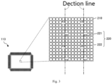
- Fig. 3 is a schematic view of a pixel arrangement of the first photographing element 113.
- the second photographing element 114 is the same as the first photographing element 113, the first photographing element 113 will be described here.
- the first photographing element 113 is a photographing element including a two-dimensional arrangement of ordinary pixels 210 that output an image signal dedicated to generating an image and phase pixels 220 that output a phase difference signal dedicated to detecting a focus.
- Each ordinary pixel 210 is a pixel in which a photoelectric conversion component in a substantially square shape is configured without displacement relative to a micro-lens.
- a color filter of any one of RGB is configured between the micro-lens and the photoelectric conversion component.
- Each phase pixel 220 is a pixel in which, for a micro-lens, a substantially rectangular photoelectric conversion component is configured with displacement relative to an optical axis of the micro-lens, the photoelectric conversion component being similar in shape to one of two portions, into which the photoelectric conversion component of an ordinary pixel is divided.
- no color filter is arranged between the micro-lens and the photoelectric conversion component.
- all the adjacent pixels are ordinary pixels 210, in other words, each phase pixel 220 is surrounded by the ordinary pixels 210 and arranged discretely.
- phase pixels 220 There are two types of phase pixels 220, namely a first phase pixel 221 whose photoelectric conversion component is shifted in the first direction (the lower side in the drawings) and a second phase pixel 222 whose photoelectric conversion component is shifted in the direction opposite to the first direction (the upper side in the drawings).
- the first phase pixels 221 and the second phase pixels 222 are arranged in predetermined patterns, respectively. Specifically, a plurality of detection lines are set along the displacement direction (up and down direction in the drawings) of the displacement pixels.
- the first phase pixels 221 are periodically arranged on one side (right side in the drawings) of each detection line, and the second phase pixels 222 are arranged out of phase on the other side (left side in the drawings) with the same period.
- the detection line is set along one axial direction as the up-down direction.
- the detection line may also be set in the orthogonal direction (the left-right direction in the example of the figure), and the phase pixels (the phase pixels shifted to the right and the phase pixels shifted to the left in the example of the figure) may be arranged suitable for the detection line.
- each phase pixel is preferably surrounded by ordinary pixels. If the detection lines are set in two orthogonal axial directions in this way, the focusing accuracy can be improved.
- the photographing device 100 in embodiments of the present invention refers to the second defocus information acquired from the phase difference signal output from the second photographing element 123 of the second camera unit 120, to perform the focus control over the first optical system 111.
- the following describes the focus control in sequence with specific scenes.
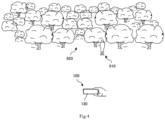
- Fig. 4 a schematic view of a scene as a subject to be photographed. Specifically, it is shown that the user attempts to photograph a scene in which the forest 920 is spread behind the person 910 as the main subject through the photographing device 100. Here, it is assumed that the user wants to focus on the person 910. The user can determine the composition of picture while confirming the live view images continuously acquired through the first camera unit 110 or the second camera unit 120 and displayed on the display 130.
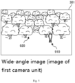
- the focus control component calculates defocus information for the background area with high spatial frequency.
- the focusing lens of the first optical system 111 is driven based on the defocus information calculated in this way, the first optical system 111 focuses on the forest 920 as the background, and the wide-angle image 301 generated after this focusing shows that the person 910 as the main subject is a blurred image.
- the focus control component calculates defocus information based on the waveform generated by the phase difference signals output from the phase pixels 220 included in the primary area.
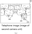
- Fig. 6 is a schematic view of an image acquired from the second camera unit 120 when the autofocus control over the second optical system 121 is performed on the same scene by the phase difference signal from the second camera unit 120.
- the second optical system 121 of the second camera unit 120 has a telephoto angle compared with the first optical system 111, so the proportion of the image area (primary area) of the person 910 in the whole area is larger than that in the case of Fig. 5 . Then, the number of phase pixels 220 included in the primary area also increases, and the finer parts of the person 910 are distinguished, so the spatial frequency thereof becomes higher.
- the focus control component can calculate defocus information for the primary area.
- the focusing lens of the second optical system 121 is driven based on the defocus information calculated in this way, the second optical system 121 focuses on the person 910 as the main subject, and as shown in the drawings, the telephoto image 302 generated after the focusing is an image in which the focus is focused on the person 910.
- Fig. 7 is a schematic view of an image acquired from the first camera unit 110 when autofocus control over the first optical system 111 is performed with reference to the second defocus information.
- the focus control component determines the first focus area 310 as the focus area in the first camera unit 110 based on the area information of the second focus area 320 included in the second defocus information.
- the first camera unit 110 and the second camera unit 120 are arranged close to each other, and the optical axis of the first optical system 111 and the optical axis of the second optical system 121 are parallel to each other. Therefore, for the sake of simplicity, regardless of the depth of the subject, a conversion formula or a reference table that can correspond to each other one by one can be prepared in advance based on each viewing angle.
- the focus control component determines the first focus area 310 based on the area information of the second focus area 320 by using this conversion formula or reference table.
- the focus control component When the first focus area 310 is determined, the focus control component performs focus control over the first optical system 111 on the premise that there is a main subject in this area. Specifically, among the phase difference signals output by the first photographing element 113, a phase waveform is generated only for the phase difference signals included in the first focus area 310. Furthermore, the focus range (i.e., the depth range in which the main subject is supposed to exist) is defined by referring to the out-of-focus amount and the out-of-focus direction of the second defocus information, so that it is not affected by the background area. According to the conditions defined in this way, the out-of-focus amount and the out-of-focus direction as the first defocus information are determined.
- the focus control component determines the moving direction and amount of the focusing lens of the first optical system 111 based on the determined out-of-focus amount and out-of-focus direction, and by moving in this way, it is possible to focus on the person 910 as the main subject.
- the focus control component After the focusing lens moves, the focus control component causes the first photographing element 113 to output the phase difference signal again, evaluates its phase waveform, and determines whether it is in a focus state. When it is determined that it is in the focus state, shooting processing is executed to generate a wide-angle image 301. When it is determined that the focus state is not reached, the first defocus information can be acquired again to correct the position of the focusing lens. Alternatively, the position of the focusing lens may be corrected while the focusing lens is wobbling, so that the contrast of a partial image generated from an image signal output from an ordinary pixel included in the first focus area 310 is the highest. The latter is called contrast AF. In addition, more simply, after determining the first focus area 310 based on the second focus area 320, the focus control component may immediately perform contrast AF on the first focus area 310 without acquiring the first defocus information from the first photographing element 113.
- the focus control component may also perform the focus control over the first optical system with reference to the second defocus information. That is, when it is determined that the focus control over the first optical system 111 is performed based on the first defocus information, the focus control over the first optical system may be performed without referring to the second defocus information. For example, it can be judged whether it is difficult to perform the focus control over the first optical system 111 based on the first defocus information by whether the focus evaluation value in the first defocus information is less than a threshold or more than a threshold.
- the second defocus information can be acquired in parallel with the acquisition of the first defocus information, and the judgment can be made by comparing each out-of-focus amount and out-of-focus direction. Specifically, if the depth of the object calculated from the out-of-focus amount and out-of-focus direction included in the first defocus information and the depth of the object calculated from the out-of-focus amount and out-of-focus direction included in the second defocus information are within a fixed range, it is assumed that the same object is captured, so it is determined that the focus control over the first optical system 111 can be performed based on the first defocus information. If it is not within the fixed range, it is assumed that different subjects are captured respectively and is determined that it is difficult to perform focus control over the first optical system 111 based on the first defocus information.
- Fig. 8 is an explanatory diagram for explaining the correspondence between two focus areas. Specifically, the figure shows that the first camera unit 110 and the second camera unit 120 capture a person existing at a distance d1 from the photographing device 100 and a person existing at a distance d2 from the photographing device, respectively, and a telephoto image 302 and a wide-angle image 301 thus captured.
- the first focus area 310 is shifted to the right when a person exists at a distance d1 compared with when a person exists at a distance d2.
- This correspondence can be calculated by triangulation. Specifically, when the distance between the second focus area 320 and the person as the main subject is calculated in the telephoto image 302, the first focus area 310 in the wide-angle image 301 can be determined using the baseline length as the distance between the optical axes of the two optical systems and the viewing angle ratio of the two optical systems. In addition, the distance to the person can be calculated according to the out-of-focus amount and direction in the second defocus information and the position of the focusing lens at that time.
- the focus control component determines the first focus area 310 corresponding to the second focus area 320 more accurately in this way, the accuracy of the focus control over the first optical system 111 can be further improved.
- this predetermined focus area can be used as the first focus area 310.
- this predetermined region can be used as the first focus region 310. Even in this case, if it is determined that it is difficult to perform the focus control over the first optical system 111 based on the first defocus information, the focus control over the first optical system 111 can be performed by determining the second focus area 320 and referring to the second defocus information in this area.
- Fig. 9 is a flow chart showing the primary processing procedure until the system control component 150 generates a wide-angle image. For example, the flow starts from a time point when the user presses the shutter button 161.
- step S101 the focus control component acquires the first defocus information. Specifically, as described above, the first photographing element 113 is driven to make the phase pixel 220 output the phase difference signal, and various operations are performed to acquire the first defocus information.
- step S102 the focus control component acquires the second defocus information in the same way as the acquisition of the first defocus information. The processing of step S102 may be performed in parallel with step S101.
- step S103 the focus control component judges whether the focus control over the first optical system 111 can be performed based on the first defocus information. If yes, skip step S104 and proceed to step S105, and if no, proceed to step S104.
- the focus control component determines the first focus area 310 in the first photographing element 113 with reference to the second defocus information acquired in step S102 and proceeds to step S105.
- the focus control component moves the focusing lens of the first optical system 111 based on the first defocus information to focus on the main subject.
- the first defocus information is acquired again by imposing a restriction condition, and the focusing lens of the first optical system 111 is moved based on the first defocus information to focus on the main subject.
- the focus control component proceeds to step S106, and causes the first photographing element 113 to output the phase difference signal again, evaluates its phase waveform, and determines whether it is in focus. When it is determined that it is in focus, step S107 is skipped and step S108 is entered. When it is determined that it is not in focus, step S107 is entered.
- step S107 the focus control component executes contrast AF to correct the position of the focusing lens so as to focus on the main subject. Then, step S108 is entered.
- the system control component 150 drives the first photographing element 113 to make ordinary pixels output image signals and make the image processing component 153 generate image data.
- the system control component 150 stores the generated image data in the storage component 170 or displays it on the display 130 according to a preset instruction, or sends it to an external device through the communication interface 180, thereby completing a series of processing.
- a plurality of pieces of defocus information may also be acquired while changing the position of the focusing lens to perform focus control.
- the position of the focusing lens can be changed several times according to its characteristics, and the defocus information of each time can be acquired.
- the moving range of the focusing lens can be determined based on the applied voltage.
- such a liquid lens can be a zoom lens with high magnification, for example, in a telephoto region, if the focusing lens is only allowed to move within this range on the premise of focusing on a subject other than 1.5m, the acquisition time of defocus information can be shortened.
- the liquid lens can be a wide-angle lens or a telephoto lens. Because the liquid lens needs to change the thickness of the liquid unit through the motor during focusing, the required stroke during focusing is long or the moving speed of the motor is slow, which may affect the focusing speed. At this time, the optical system including the liquid lens can be assisted in focus control based on the defocus information of other optical systems. For example, a plurality of focusing distance intervals are determined, so that the liquid lens only needs to focus in a small range, thereby improving the focusing speed.
- 100... photographing device 110... first camera unit, 111... first optical system, 112... first driving mechanism, 113... first photographing element, 114... first analog front end (AFE), 120... second camera unit, 121... second optical system, 122... second driving mechanism, 123... second photographing element, 124... second analog front end (AFE), 130... display, 150... system control component, 151... working memory, 152... image processing component, 160... operation component, 161... shutter button, 162... touch panel, 170... storage component, 180... communication interface, 210... ordinary pixel, 220... phase pixel, 221... first phase pixel, 222... second phase pixel, 301... wide-angle image, 302... telephoto image, 310... first focus area, 320... second focus area, 910... person, 920... forest.
Landscapes
- Engineering & Computer Science (AREA)
- Multimedia (AREA)
- Signal Processing (AREA)
- Physics & Mathematics (AREA)
- General Physics & Mathematics (AREA)
- Optics & Photonics (AREA)
- Human Computer Interaction (AREA)
- Studio Devices (AREA)
- Focusing (AREA)
- Lens Barrels (AREA)
- Cameras In General (AREA)
- Automatic Focus Adjustment (AREA)
Applications Claiming Priority (1)
| Application Number | Priority Date | Filing Date | Title |
|---|---|---|---|
| PCT/CN2022/094276 WO2023221141A1 (fr) | 2022-05-20 | 2022-05-20 | Appareil photographique et programme de commande de mise au point |
Publications (2)
| Publication Number | Publication Date |
|---|---|
| EP4529150A1 true EP4529150A1 (fr) | 2025-03-26 |
| EP4529150A4 EP4529150A4 (fr) | 2025-06-18 |
Family
ID=88834417
Family Applications (1)
| Application Number | Title | Priority Date | Filing Date |
|---|---|---|---|
| EP22941860.3A Pending EP4529150A4 (fr) | 2022-05-20 | 2022-05-20 | Appareil photographique et programme de commande de mise au point |
Country Status (6)
| Country | Link |
|---|---|
| US (1) | US12593126B2 (fr) |
| EP (1) | EP4529150A4 (fr) |
| JP (1) | JP2024522409A (fr) |
| KR (1) | KR20230167074A (fr) |
| CN (1) | CN117546475A (fr) |
| WO (1) | WO2023221141A1 (fr) |
Family Cites Families (15)
| Publication number | Priority date | Publication date | Assignee | Title |
|---|---|---|---|---|
| JP5219865B2 (ja) | 2008-02-13 | 2013-06-26 | キヤノン株式会社 | 撮像装置及び焦点制御方法 |
| JP5910739B2 (ja) * | 2012-05-28 | 2016-04-27 | 株式会社ニコン | 撮像装置 |
| KR102157675B1 (ko) * | 2014-07-25 | 2020-09-18 | 삼성전자주식회사 | 촬영 장치 및 그 촬영 방법 |
| CN105376474B (zh) * | 2014-09-01 | 2018-09-28 | 光宝电子(广州)有限公司 | 图像采集装置及其自动对焦方法 |
| JP6362511B2 (ja) | 2014-11-04 | 2018-07-25 | キヤノン株式会社 | 撮像装置及びその制御方法 |
| KR102446442B1 (ko) * | 2015-11-24 | 2022-09-23 | 삼성전자주식회사 | 디지털 촬영 장치 및 그 동작 방법 |
| CN106603911A (zh) * | 2016-11-29 | 2017-04-26 | 广东欧珀移动通信有限公司 | 控制方法、控制装置及电子装置 |
| JP2018169517A (ja) * | 2017-03-30 | 2018-11-01 | ソニーセミコンダクタソリューションズ株式会社 | 撮像装置、撮像モジュールおよび撮像装置の制御方法 |
| KR20190132627A (ko) | 2017-04-19 | 2019-11-28 | 엘지전자 주식회사 | 이동 단말기 |
| TWI662694B (zh) * | 2017-12-20 | 2019-06-11 | 緯創資通股份有限公司 | 三維影像攝取方法及系統 |
| KR102697423B1 (ko) | 2018-09-21 | 2024-08-22 | 엘지이노텍 주식회사 | 카메라 모듈 및 이의 동작 방법 |
| JP7321290B2 (ja) * | 2019-11-29 | 2023-08-04 | 富士フイルム株式会社 | 情報処理装置、情報処理方法、及びプログラム |
| US12393000B2 (en) * | 2020-02-25 | 2025-08-19 | Zebra Technologies Corporation | Optical arrangement for small size wide angle auto focus imaging lens for high resolution sensors |
| JP7159371B2 (ja) | 2020-04-22 | 2022-10-24 | キヤノン株式会社 | 制御装置、その制御方法、およびプログラム |
| CN112004026B (zh) * | 2020-09-01 | 2021-06-29 | 北京小米移动软件有限公司 | 相位对焦装置、方法、拍摄方法、装置、终端设备及介质 |
-
2022
- 2022-05-20 US US18/559,625 patent/US12593126B2/en active Active
- 2022-05-20 EP EP22941860.3A patent/EP4529150A4/fr active Pending
- 2022-05-20 CN CN202280001794.6A patent/CN117546475A/zh active Pending
- 2022-05-20 KR KR1020237037882A patent/KR20230167074A/ko active Pending
- 2022-05-20 JP JP2022538156A patent/JP2024522409A/ja active Pending
- 2022-05-20 WO PCT/CN2022/094276 patent/WO2023221141A1/fr not_active Ceased
Also Published As
| Publication number | Publication date |
|---|---|
| WO2023221141A1 (fr) | 2023-11-23 |
| JP2024522409A (ja) | 2024-06-21 |
| KR20230167074A (ko) | 2023-12-07 |
| CN117546475A (zh) | 2024-02-09 |
| US12593126B2 (en) | 2026-03-31 |
| EP4529150A4 (fr) | 2025-06-18 |
| US20250097574A1 (en) | 2025-03-20 |
Similar Documents
| Publication | Publication Date | Title |
|---|---|---|
| JP3992992B2 (ja) | 被写体像取得装置 | |
| JP5388544B2 (ja) | 撮像装置およびそのフォーカス制御方法 | |
| US8634711B2 (en) | Image capture apparatus and method | |
| US7978968B2 (en) | Auto focus device | |
| JP4843002B2 (ja) | 撮像装置、および撮像装置制御方法、並びにコンピュータ・プログラム | |
| US8648961B2 (en) | Image capturing apparatus and image capturing method | |
| JP3823921B2 (ja) | 撮像装置 | |
| JP4094458B2 (ja) | 画像入力装置 | |
| JP4730478B2 (ja) | 撮像装置、および撮像装置制御方法、並びにプログラム | |
| US20110164868A1 (en) | Method and apparatus for applying multi-autofocusing (af) using contrast af | |
| JP5896763B2 (ja) | 光学機器および自動焦点調節を行う方法 | |
| KR20080092875A (ko) | 자동 포커스 장치, 촬상 장치 및 자동 포커스 방법 | |
| US12395733B2 (en) | Systems and methods for obtaining a super macro image | |
| US20100103276A1 (en) | Split aperture capture of rangemap for 3d imaging | |
| JP2016142924A (ja) | 撮像装置及びその制御方法、プログラム、記憶媒体 | |
| JP2015043026A (ja) | 撮像装置及びその制御方法 | |
| JP2014142497A (ja) | 撮像装置及びその制御方法 | |
| US12593126B2 (en) | Photographing device and focus control method | |
| JP2011176457A (ja) | 電子カメラ | |
| JP2018005021A (ja) | オートフォーカスモジュール及びビデオカメラ | |
| KR20120068696A (ko) | 촬상 장치 및 촬상 방법 | |
| JP4535462B2 (ja) | 被写体像取得装置 | |
| JP2006267220A (ja) | オートフォーカスシステム | |
| JP6900228B2 (ja) | 撮像装置、撮像システム、撮像装置の制御方法、および、プログラム | |
| JP2014003417A (ja) | 撮像装置 |
Legal Events
| Date | Code | Title | Description |
|---|---|---|---|
| STAA | Information on the status of an ep patent application or granted ep patent |
Free format text: STATUS: UNKNOWN |
|
| STAA | Information on the status of an ep patent application or granted ep patent |
Free format text: STATUS: THE INTERNATIONAL PUBLICATION HAS BEEN MADE |
|
| PUAI | Public reference made under article 153(3) epc to a published international application that has entered the european phase |
Free format text: ORIGINAL CODE: 0009012 |
|
| STAA | Information on the status of an ep patent application or granted ep patent |
Free format text: STATUS: REQUEST FOR EXAMINATION WAS MADE |
|
| 17P | Request for examination filed |
Effective date: 20231121 |
|
| AK | Designated contracting states |
Kind code of ref document: A1 Designated state(s): AL AT BE BG CH CY CZ DE DK EE ES FI FR GB GR HR HU IE IS IT LI LT LU LV MC MK MT NL NO PL PT RO RS SE SI SK SM TR |
|
| REG | Reference to a national code |
Ref country code: DE Ref legal event code: R079 Free format text: PREVIOUS MAIN CLASS: H99Z9999999999 Ipc: H04N0023670000 |
|
| A4 | Supplementary search report drawn up and despatched |
Effective date: 20250520 |
|
| RIC1 | Information provided on ipc code assigned before grant |
Ipc: H04N 23/55 20230101ALI20250514BHEP Ipc: H04N 23/45 20230101ALI20250514BHEP Ipc: H04N 23/60 20230101ALI20250514BHEP Ipc: H04N 23/90 20230101ALI20250514BHEP Ipc: H04N 23/00 20230101ALI20250514BHEP Ipc: H04N 23/67 20230101AFI20250514BHEP |
|
| DAV | Request for validation of the european patent (deleted) | ||
| DAX | Request for extension of the european patent (deleted) |