EP4529171A2 - Verfahren und vorrichtungen zur codierung und decodierung einer mehransichtsvideosequenz - Google Patents
Verfahren und vorrichtungen zur codierung und decodierung einer mehransichtsvideosequenz Download PDFInfo
- Publication number
- EP4529171A2 EP4529171A2 EP25156393.8A EP25156393A EP4529171A2 EP 4529171 A2 EP4529171 A2 EP 4529171A2 EP 25156393 A EP25156393 A EP 25156393A EP 4529171 A2 EP4529171 A2 EP 4529171A2
- Authority
- EP
- European Patent Office
- Prior art keywords
- image
- sub
- data
- depth
- coded
- Prior art date
- Legal status (The legal status is an assumption and is not a legal conclusion. Google has not performed a legal analysis and makes no representation as to the accuracy of the status listed.)
- Pending
Links
Images




Classifications
-
- G—PHYSICS
- G06—COMPUTING OR CALCULATING; COUNTING
- G06T—IMAGE DATA PROCESSING OR GENERATION, IN GENERAL
- G06T9/00—Image coding
-
- H—ELECTRICITY
- H04—ELECTRIC COMMUNICATION TECHNIQUE
- H04N—PICTORIAL COMMUNICATION, e.g. TELEVISION
- H04N19/00—Methods or arrangements for coding, decoding, compressing or decompressing digital video signals
- H04N19/44—Decoders specially adapted therefor, e.g. video decoders which are asymmetric with respect to the encoder
-
- H—ELECTRICITY
- H04—ELECTRIC COMMUNICATION TECHNIQUE
- H04N—PICTORIAL COMMUNICATION, e.g. TELEVISION
- H04N19/00—Methods or arrangements for coding, decoding, compressing or decompressing digital video signals
- H04N19/46—Embedding additional information in the video signal during the compression process
-
- H—ELECTRICITY
- H04—ELECTRIC COMMUNICATION TECHNIQUE
- H04N—PICTORIAL COMMUNICATION, e.g. TELEVISION
- H04N19/00—Methods or arrangements for coding, decoding, compressing or decompressing digital video signals
- H04N19/50—Methods or arrangements for coding, decoding, compressing or decompressing digital video signals using predictive coding
- H04N19/597—Methods or arrangements for coding, decoding, compressing or decompressing digital video signals using predictive coding specially adapted for multi-view video sequence encoding
Definitions
- one or more views are calculated from the decoded views.
- FIG. 2 An example of a synthesis algorithm is illustrated in Figure 2 showing mainly the inputs/outputs of a view synthesis algorithm.
- the synthesis algorithm is able to synthesize a viewpoint " v " located in a given volume, called the viewing volume, depending on the positioning of the cameras.
- the n views and the synthesized view are composed of both texture data (T 1 -T 4 , T v ) and depth data (D 1 -D 4 , D v ) which make it possible to represent the distance of the elements of the scene relative to the cameras.
- the depth data is classically represented in the form of a depth map, i.e. an image indicating at each point of the image the depth associated with the object represented at this point.
- MV-HEVC and 3D-HEVC encoders are two extensions of the 2D HEVC encoder ("High Efficiency Video Coding, Coding Tools and Specification", Matthias Wien, Signals and Communication Technology, 2015 ) suitable for encoding multi-view videos.
- Such encoders take as input a set of views and optionally the associated depth maps.
- the MV-HEVC encoder does not apply any specific block-level coding tool. To encode an image from a current view, it simply uses, in addition to the previously encoded/decoded images of the current view, an image from another view as a reference image.
- the 3D-HEVC encoder adds specific tools for depth map encoding, and uses more advanced inter-view redundancies, and inter-component redundancies, where depth map encoding takes advantage of texture encoding.
- depth map encoding takes advantage of texture encoding.
- FIG. 3 illustrates another method for encoding multi-view videos and for synthesizing intermediate views on the decoder side.
- one or more basic views are encoded with a 2D encoder, for example an HEVC type encoder, or with a multi-view encoder.
- the other views (T s , D s ) undergo processing which allows certain areas to be extracted from each of these views.
- the occlusion zones increase. These zones correspond to objects that are hidden in the views transmitted to the decoder but which are necessary to reconstruct an image from any point of view in the viewing volume.
- the extracted zones can thus correspond to the occlusion zones that are hidden in the base views but which are visible in the views not transmitted to the decoder.
- Undersampling views can also lead to significant defects in view synthesis, particularly when an object is very distorted depending on the viewing position, i.e. the synthesized viewpoint.
- the extracted areas also called patches hereinafter, are coded for example by a classic 2D video coder.
- the synthesis algorithm can then produce one or more intermediate views from the basic views and the decoded patches.
- patches allow information to be transmitted to the decoder relating to the same area that can be seen from one viewpoint of a base view or from another viewpoint, so as to be able to take into account a change in illumination between the two viewpoints, or for example poor projection quality, linked to the object itself, for example in the case of an inclined object (which extends over a certain depth interval).
- the patches In order to encode the patches representing the extracted areas, it is necessary to encode the texture of these patches and the associated depth. To simplify the coding and representation of these patches, which can have different shapes, in general, the patches are stored in the form of rectangular images or at least in the form of quadrilaterals, also called sub-images.
- the sub-images include so-called useful data corresponding to the extracted areas and likely to be used for the synthesis of intermediate views, and non-useful data not initially belonging to the extracted patches.
- the invention improves the state of the art. To this end, it relates to a method for decoding at least one data stream representative of a multi-view video.
- the data stream comprises at least coded data representative of at least one sub-image, the coded data comprising texture data and depth data associated with said texture data, and the sub-image comprising at least one zone, called useful, intended to be used to generate at least one image of at least one view.
- Such a special value allows the synthesis algorithm to not use pixels that do not belong to the useful area when synthesizing a view.
- the sub-image may include texture and depth data relating to an area visible from views encoded in the data stream. data, but resulting in significant defects in the synthesis of a view. Coding such a sub-image makes it possible to improve the quality of the synthesis of this view by providing texture and depth refinements to the area.
- the proposed invention allows for better adaptation to the content of the views and to the types of occlusion.
- the first method allows for preserving clear contours of the occlusion zones during synthesis
- the second method allows for saving coding costs by avoiding the transmission of the binary map.
- the sharpness of the contours of the occlusion zones is not preserved.
- the choice at the encoder between the first method and the second method can be made for example via a flow/distortion optimization in which the distortion is measured at the encoder from a partial synthesis of the area reconstructed by the useful area.
- the assignment depth value is determined from a minimum depth value determined on at least the useful area of the sub-image, reduced by a predetermined value.
- a binary map indicating the pixels belonging to the useful area can thus be created for the sub-images coded according to the second method, since the decoder is aware of the so-called assignment depth value which has been assigned to the pixels located outside the useful area. It can thus identify from the decoded pixel depth value which pixels belong to the useful area and which pixels are outside the useful area.
- the binary map thus constructed can be transmitted to the synthesis algorithm. The information provided as input to the synthesis algorithm are thus identical, whether the sub-image was coded using the first method or the second method.
- the depth data of the sub-image coded in the data stream comprise, for at least one pixel of the sub-image, a residue determined by a difference between the depth value of said pixel and said assignment depth value.
- This particular embodiment of the invention makes it possible to reduce the cost of coding the depth data for the sub-image when the sub-image is coded according to the second method. Indeed, when the sub-image only comprises background information, the dynamics of the depth data is low and the coding of this data in the form of a residue is more advantageous.
- an indicator is decoded or coded for said at least one sub-image indicating whether the depth data is coded by a residue determined by a difference between the depth value of said pixel and said assignment depth value.
- This particular embodiment of the invention makes it possible to signal whether the depth data in the case of coding by the second method are coded by a residue or not. Indeed, depending on the type of information carried by the sub-image, the residual coding mode may or may not be advantageous. Residual coding may be advantageous when the sub-image carries information relating to occlusion zones, whereas it may be less interesting for sub-images comprising refinement information.
- the infinite value assigned to the depth values makes it possible to simply indicate to the synthesis algorithm the pixels belonging to the useful zone and to the non-useful zone and avoids the transmission to the synthesis module of additional data, such as a binary map indicating the useful zone and the non-useful zone.
- At least two sub-images intended to be used to generate said at least one image of said at least one view are coded in the data stream, the minimum depth value is determined from each useful area of said at least two sub-images.
- the data stream comprises coded data of at least one view of the video, said at least one view corresponding to a view determined during coding from at least one source view.
- a source view here refers to an original view of the scene represented by the multi-view video. In other words, it is a sequence of images resulting from a capture of the scene by a camera.
- At least one basic view transmitted to the decoder is a view determined from one or more source views. This determination can be carried out during coding or prior to coding.
- it could be a view synthesized from multiple source views or a view calculated/estimated from multiple source viewpoints.
- the determined view may correspond to a sequence of images in which each image is larger than an image from a camera and includes all images of the same instant from all cameras in a 360° camera array.
- the decoding method further comprises receiving the texture data and the depth data of said sub-image, said sub-image coming from an intermediate view synthesized for a position and a viewing direction of an observer in a viewing volume.
- the sub-image data is provided to the decoder, upon request for a position and a viewing direction in the viewing volume.
- Such a particular embodiment of the invention makes it possible to provide the sub-image data on demand, during the navigation of an observer in the multi-view video.
- the data of the corresponding refinement or occlusion zones are thus more adapted to the position and viewing direction of the observer.
- such a decoding device is included in a terminal or a server.
- such a coding device is included in a terminal or a server.
- the data stream further comprises, when the indicator indicates that the sub-image is coded according to the second method, information representative of the assignment depth value.
- the data stream comprises an indicator for said at least one sub-image indicating whether the depth data is encoded by obtaining a residue determined by a difference between the depth value of a pixel and said assignment depth value.
- the data stream further comprises coded data of at least one view of the video, said at least one view corresponding to a view synthesized during coding from at least one source view.
- the decoding method, respectively the coding method, according to the invention can be implemented in various ways, in particular in wired form or in software form.
- the decoding method, respectively the coding method is implemented by a computer program.
- the invention also relates to a computer program comprising instructions for implementing the decoding method or the coding method according to any one of the particular embodiments described above, when said program is executed by a processor.
- Such a program can use any programming language. It can be downloaded from a communications network and/or recorded on a computer-readable medium.
- This program may use any programming language, and may be in the form of source code, object code, or code intermediate between source code and object code, such as in a partially compiled form, or in any other desirable form.
- the invention also relates to a recording medium or information medium readable by a computer, and comprising instructions of a computer program as mentioned above.
- the recording media mentioned above can be any entity or device capable of storing the program.
- the medium can comprise a storage means, such as a ROM, for example a CD ROM or a microelectronic circuit ROM, a USB key, or even a magnetic recording means, for example a hard disk.
- the recording media can correspond to a transmissible medium such as an electrical or optical signal, which can be conveyed via an electrical or optical cable, by radio or by other means.
- the program according to the invention can in particular be downloaded from a network such as the Internet.
- the recording media may correspond to an integrated circuit in which the program is incorporated, the circuit being adapted to execute or to be used in the execution of the method in question.
- FIG. 4 illustrates steps of a method for coding at least one data stream representative of a multi-view video according to a particular embodiment of the invention.
- the multi-view video is encoded according to a coding scheme as presented in relation to the Figure 3 in which one or more so-called basic views are coded in the data stream and in which sub-images or patches comprising texture and depth data are also coded in the data stream and allow the decoder to synthesize other views of the scene which have not been coded in the data stream.
- a coding scheme as presented in relation to the Figure 3 in which one or more so-called basic views are coded in the data stream and in which sub-images or patches comprising texture and depth data are also coded in the data stream and allow the decoder to synthesize other views of the scene which have not been coded in the data stream.
- each view is therefore a video, i.e., a sequence of images, and for each image of the view, a depth map is determined.
- the views V0-V3 and the associated depth maps d0-d3 are coded and decoded, for example by a HEVC encoder, or any other suitable 2D or multi-view encoder. These views are considered as basic views and will be transmitted to the decoder. They may be used to synthesize intermediate views on the decoder side. Alternatively, not all the views V0-V3 may be coded, for example a single view, or 2 or 3 may be coded and transmitted to the decoder.
- a basic view coded in the data stream corresponds to a view synthesized from one or more views V0-V3.
- an intermediate view Vi is synthesized using the coded views and which will be transmitted to the decoder.
- an intermediate view Vi comprises texture data and depth data associated with the texture data.
- a step E42 from this intermediate view Vi and the coded/decoded basic views, one or more zones are extracted from the intermediate view Vi.
- the method is presented here in the case of a synthesized intermediate view Vi. Of course, the method applies in an identical manner if several intermediate views are synthesized, one or more zones being extracted from these intermediate views.
- the object of the invention does not lie in determining the areas to be extracted. The method of extracting these areas will therefore not be developed further.
- the extracted areas may correspond to occlusion areas, i.e. areas not visible in the base views and visible in the intermediate view, or to areas already present in the base views but providing insufficient synthesis quality in the synthesized view, for example because of deformations appearing in the synthesis.
- the synthesized intermediate view then corresponds to a view captured by a camera.
- the intermediate view from which the zones are extracted can be a view captured by a camera but not encoded in the data stream. It can therefore be synthesized on the decoder side and refined by the sub-images encoded in the data stream.
- a sub-image includes texture data, depth data, a position in each view, and a size.
- one or more sub-images can be extracted for the same image of the intermediate view.
- a sub-image representing the same area extracted from the intermediate view can be extracted for different images of the intermediate view.
- the texture and depth data of the sub-image then vary over time and form a sequence of sub-images.
- Examples of sub-images P 0 -P 5 extracted from an image of the intermediate view Vi are illustrated in Figure 5 .
- the sub-images are grouped into a rectangular image 50 in order to facilitate their coding.
- the image 50 can comprise sub-images extracted from different images of the intermediate view, or from a single image, or even sub-images extracted from the intermediate view Vi and also from other intermediate views.
- sub-images can be encoded without being grouped into a rectangular image. Each sub-image is then treated as an image or sequence of images when the sub-image varies over time.
- the sub-images include so-called useful data (51, areas with large hatching on the Figure 5 ) corresponding to the extracted areas which are likely to be used for the synthesis of the intermediate view or other views, and so-called non-useful data (52, areas with fine hatching on the Figure 5 ) which include texture and depth data at 0.
- useful data areas with large hatching on the Figure 5
- non-useful data areas with fine hatching on the Figure 5
- the useful data of the sub-image can be included in one area of the sub-image or in several disjoint areas of the sub-image, so that the sub-image then includes several areas said to be useful for synthesis.
- the invention is described in the case where it is considered that the sub-images are grouped into a large image 50.
- the general principle of the invention applies in a similar manner to the case where the sub-images are not grouped into a large image but processed individually.
- the sub-image(s) are coded.
- two methods of coding the sub-images can be used.
- a competition between the two coding methods is implemented in order to select the coding method offering the best bit rate/distortion compromise.
- An indicator is coded in the stream to indicate, for the sub-image, which coding method is used.
- the sub-image is coded using a binary map indicating, for a considered pixel of the sub-image, whether the pixel belongs to the useful zone (for example in the binary map, the pixel takes the value 1) or not (for example in the binary map, the pixel takes the value 0).
- FIG. 6 illustrates an example of an image (50 text ) comprising sub-images and a corresponding binary map (50 bin ) indicating the useful areas (51, hatched areas in the texture image 50 text ) and non-useful areas (52, white areas in the texture image 50 text ) of the sub-images for the image 50 illustrated in Figure 5 .
- this first coding method only the texture and depth data of the pixels located in the useful area are coded and transmitted to the decoder, the associated binary map being coded for all the pixels of the sub-image.
- a predefined value as a reference in the texture data, for example, such as a 0, which would specify that the pixel in question is not useful. Indeed, after encoding and decoding the texture, the value of the pixel is not guaranteed, and may no longer be zero. In addition, other zero values may appear for pixels belonging to the useful area.
- the sub-image is coded using a filling of the non-useful area, both for texture data and for depth data.
- the sub-image is then coded in a conventional manner by coding all the pixels of the sub-image.
- the coding method to be used to code the sub-image is determined, from among the first method and the second method mentioned above. For example, a competition between the coding of the two methods is implemented and the method providing the best rate/distortion compromise is selected. In a known manner, such competition is carried out by a simulation of the coding respectively according to the two methods, a calculation of the rate used by each method and the associated distortion calculated between the original values and the reconstructed values of the texture and/or depth data.
- step E421 an indicator indicating whether the sub-image is coded according to the first method or according to the second method is coded in the data stream.
- the indicator indicates that the sub-image is coded according to the first method
- the method proceeds to step E422.
- the indicator indicates that the sub-image is coded according to the second method, the method proceeds to step E424.
- step E422 the binary map of the sub-image is encoded.
- entropy coding is used.
- the texture data and the depth data are coded for the sub-image by considering only the pixels located in the useful area of the sub-image. These pixels are identified using the binary map.
- the texture data and the depth data are coded in a conventional manner, for example by an HEVC encoder or any other 2D or 3D encoder.
- step E424 the indicator indicating that the sub-image is coded according to the second method, an assignment depth value d* is determined.
- the assignment depth value d* is determined from a minimum depth value d min determined on at least the useful area of the sub-image, reduced by a predetermined value delta.
- This minimum value d min is reduced by a delta value to take into account the quantization error introduced during the coding of the depth values.
- delta is equal to 10.
- the minimum depth value is determined from the useful area of several sub-images. For example, when the sub-images are grouped in a large image, the useful areas of all the sub-images are scanned in order to determine the minimum depth value among all the sub-images of the large image.
- Such a particular embodiment of the invention makes it possible to have a more homogeneous assignment depth value for all the sub-images of a large image.
- a step E425 the assignment depth value d* is assigned as a depth value to the pixels located outside the useful area.
- Such a step is illustrated in figure 8 representing depth data of a sub-image.
- the pixels of the useful area (51) include the depth value that was estimated for these pixels when extracting the useful area from the intermediate view.
- the pixels of the non-useful area (52) include the assignment depth value d*.
- step E426 a texture value is also assigned to the pixels located outside the useful area.
- the filling of the non-useful area is done by mirroring.
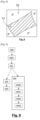
- the texture values of the pixels outside the useful area are calculated so as to best reproduce the data present inside the useful area, as shown in the Figure 7 .
- a sub-image is represented. Data from the useful area (51) are propagated into the non-useful area (52) symmetrically with respect to the boundary (53) between the useful area and the non-useful area.
- the texture values of the pixels located outside (52) of the useful area correspond to the average of the texture values of the pixels in the useful area (51).
- the pixels in the non-useful area are filled with the same value.
- the texture data and the depth data for the sub-image are coded by considering all the pixels of the sub-image.
- the pixels of the useful area and the pixels of the non-useful area are coded.
- the texture data and the depth data are coded in a conventional manner, for example by an HEVC coder or any other 2D or 3D coder.
- the depth data are differentially coded with respect to the assignment depth value d*.
- the decoder in order for the decoder to be able to reconstruct depth data for the sub-image from the residual, the decoder must have knowledge of the assignment depth value d*.
- the assignment depth value d* is coded in the data stream.
- the differential coding of the depth data is put in competition with a conventional coding of the depth data.
- step E420 when the coding of the sub-image according to the second method is tested, it is also determined whether the depth data according to this second coding method are coded by a residual or not.
- the coding of the depth data by residual and the coding of the depth data in a classical way are simulated to select the coding mode providing the best compromise between bit rate and distortion.
- information indicating which depth data coding mode is selected must then be coded in the data stream.
- a depth data coding indicator is coded in the data stream for the sub-image. Such an indicator indicates whether the depth data is coded by a residue or not.
- a binary map is decoded for the sub-image. Such a binary map indicates for a considered pixel of the sub-image, whether the pixel belongs to the useful zone or not.
- the depth data of the sub-image are reconstructed by adding to the depth residue values of the sub-image which were decoded in step E940, the decoded assignment depth value d*.
- the decoding method comprises a prior step E901 of receiving the texture and depth data of the sub-image.
- sub-image data is received following a request sent by the decoder for a viewing position and direction corresponding to the viewing position and direction of an observer in the viewing volume, or for a viewing position and direction close to those of the observer.
- FIG. 11 illustrates steps of the decoding method according to another particular embodiment of the invention.
- step E91 When the indicator decoded in step E91 indicates that the sub-image is coded according to the second method, during a step E110, the pixels of the useful zone are determined from the reconstructed depth data and the decoded assignment depth value d*.
- a binary map is constructed for the sub-image.
- Such a binary map indicates for a considered pixel of the sub-image, whether or not the pixel belongs to the useful zone.
- Such a binary map is similar to the binary map which would have been decoded in the case where the sub-image had been coded according to the first method.
- the binary map is transmitted to a synthesis module.
- FIG. 12 presents the simplified structure of a COD coding device suitable for implementing the coding method according to any of the particular embodiments of the invention.
- the steps of the coding method are implemented by computer program instructions.
- the coding device COD has the conventional architecture of a computer and notably comprises a memory MEM, a processing unit UT, equipped for example with a processor PROC, and controlled by the computer program PG stored in memory MEM.
- the computer program PG comprises instructions for implementing the steps of the coding method as described above, when the program is executed by the processor PROC.
- the code instructions of the computer program PG are for example loaded into a RAM memory (not shown) before being executed by the processor PROC.
- the processor PROC of the processing unit UT implements in particular the steps of the coding method described above, according to the instructions of the computer program PG.
- FIG. 13 presents the simplified structure of a DEC decoding device suitable for implementing the decoding method according to any of the particular embodiments of the invention.
- the decoding device DEC has the conventional architecture of a computer and notably comprises a memory MEM0, a processing unit UT0, equipped for example with a processor PROC0, and controlled by the computer program PG0 stored in memory MEM0.
- the computer program PG0 comprises instructions for implementing the steps of the decoding method as described above, when the program is executed by the processor PROC0.
- the code instructions of the computer program PG0 are for example loaded into a RAM memory (not shown) before being executed by the processor PROC0.
- the processor PROC0 of the processing unit UT0 implements in particular the steps of the decoding method described above, according to the instructions of the computer program PG0.
- FIG 14 illustrates an example of an STR data stream according to particular embodiments of the invention.
- the STR data stream is generated by the encoding method as described in connection with the Figure 4 .
- the STR data stream is representative of a multi-view video, and notably comprises V b coded data representative of one or more basic views, and coded data representative of at least one sub-image comprising texture data (text0, text1) and depth data (dpth0, dpth1) associated with said texture data.
- a basic view coded in the data stream corresponds to a view synthesized during coding from at least one source view of the scene.
- the STR data stream illustrated in figure 14 is an illustrative example. It is presented here comprising two sub-images (Im0, Im1).
- the sub-images included in the data stream comprise an area, called useful, intended to be used to generate at least one image of at least one view of the scene captured by the multi-view video.
- the STR data stream comprises information representative of the assignment depth value d*.
- the STR data stream comprises a coding indicator (Id_res) for the sub-image indicating whether the depth data are encoded by obtaining a residue determined by a difference between the depth value of a pixel and the assignment depth value d*.
- Id_res a coding indicator
- the example described above is merely illustrative and not limiting.
- the encoded data described above may be included in a single data stream or multiple data streams or sub-streams of a single data stream. Also, some of the data described above and other data not described may be included in metadata associated with one or more data streams.
- texture data and depth data can be encoded in separate streams.
- encoded data for base views may be included in a video data stream, and encoded data for subpictures may be included in metadata associated with the video data stream.
- At least two useful areas belonging respectively to at least two sub-images, said at least two useful areas being intended to be used to generate said at least one image of said at least one view, are coded in the data stream, the minimum depth value is determined from said at least two useful areas.
Landscapes
- Engineering & Computer Science (AREA)
- Multimedia (AREA)
- Signal Processing (AREA)
- Physics & Mathematics (AREA)
- General Physics & Mathematics (AREA)
- Theoretical Computer Science (AREA)
- Compression Or Coding Systems Of Tv Signals (AREA)
- Testing, Inspecting, Measuring Of Stereoscopic Televisions And Televisions (AREA)
- Image Processing (AREA)
Applications Claiming Priority (3)
| Application Number | Priority Date | Filing Date | Title |
|---|---|---|---|
| FR1902659A FR3093884A1 (fr) | 2019-03-15 | 2019-03-15 | Procédés et dispositifs de codage et de décodage d'une séquence vidéo multi-vues |
| EP20719686.6A EP3939304B1 (de) | 2019-03-15 | 2020-02-27 | Verfahren und vorrichtungen zur codierung und decodierung von mehrfachansichtssequenzen |
| PCT/FR2020/050394 WO2020188172A1 (fr) | 2019-03-15 | 2020-02-27 | Procédés et dispositifs de codage et de décodage d'une séquence vidéo multi-vues |
Related Parent Applications (2)
| Application Number | Title | Priority Date | Filing Date |
|---|---|---|---|
| EP20719686.6A Division EP3939304B1 (de) | 2019-03-15 | 2020-02-27 | Verfahren und vorrichtungen zur codierung und decodierung von mehrfachansichtssequenzen |
| EP20719686.6A Division-Into EP3939304B1 (de) | 2019-03-15 | 2020-02-27 | Verfahren und vorrichtungen zur codierung und decodierung von mehrfachansichtssequenzen |
Publications (2)
| Publication Number | Publication Date |
|---|---|
| EP4529171A2 true EP4529171A2 (de) | 2025-03-26 |
| EP4529171A3 EP4529171A3 (de) | 2025-05-28 |
Family
ID=67262654
Family Applications (2)
| Application Number | Title | Priority Date | Filing Date |
|---|---|---|---|
| EP25156393.8A Pending EP4529171A3 (de) | 2019-03-15 | 2020-02-27 | Verfahren und vorrichtungen zur codierung und decodierung einer mehransichtsvideosequenz |
| EP20719686.6A Active EP3939304B1 (de) | 2019-03-15 | 2020-02-27 | Verfahren und vorrichtungen zur codierung und decodierung von mehrfachansichtssequenzen |
Family Applications After (1)
| Application Number | Title | Priority Date | Filing Date |
|---|---|---|---|
| EP20719686.6A Active EP3939304B1 (de) | 2019-03-15 | 2020-02-27 | Verfahren und vorrichtungen zur codierung und decodierung von mehrfachansichtssequenzen |
Country Status (10)
| Country | Link |
|---|---|
| US (3) | US11659203B2 (de) |
| EP (2) | EP4529171A3 (de) |
| JP (2) | JP2022525210A (de) |
| KR (1) | KR20210135322A (de) |
| CN (2) | CN118354095A (de) |
| BR (1) | BR112021017084A2 (de) |
| ES (1) | ES3032702T3 (de) |
| FR (1) | FR3093884A1 (de) |
| PL (1) | PL3939304T3 (de) |
| WO (1) | WO2020188172A1 (de) |
Families Citing this family (4)
| Publication number | Priority date | Publication date | Assignee | Title |
|---|---|---|---|---|
| FR3093884A1 (fr) * | 2019-03-15 | 2020-09-18 | Orange | Procédés et dispositifs de codage et de décodage d'une séquence vidéo multi-vues |
| CN113727105B (zh) * | 2021-09-08 | 2022-04-26 | 北京医百科技有限公司 | 一种深度图压缩方法、装置、系统及存储介质 |
| US12604001B2 (en) | 2023-11-15 | 2026-04-14 | Tencent America LLC | Systems and methods for block partitioning and interleaved coding order for multiview video coding |
| US12615391B2 (en) * | 2023-11-20 | 2026-04-28 | Tencent America LLC | Systems and methods for loop filtering for multi-view coding |
Family Cites Families (26)
| Publication number | Priority date | Publication date | Assignee | Title |
|---|---|---|---|---|
| CN101416520B (zh) * | 2006-03-31 | 2011-12-14 | 皇家飞利浦电子股份有限公司 | 多视图的高效编码 |
| KR101545009B1 (ko) * | 2007-12-20 | 2015-08-18 | 코닌클리케 필립스 엔.브이. | 스트레오스코픽 렌더링을 위한 이미지 인코딩 방법 |
| FR2932911A1 (fr) | 2008-06-24 | 2009-12-25 | France Telecom | Procede et dispositif de remplissage des zones d'occultation d'une carte de profondeur ou de disparites estimee a partir d'au moins deux images. |
| JP5909187B2 (ja) * | 2009-10-14 | 2016-04-26 | トムソン ライセンシングThomson Licensing | フィルタ処理およびエッジ符号化 |
| JP5588833B2 (ja) * | 2010-11-10 | 2014-09-10 | 富士フイルム株式会社 | 画像圧縮装置、画像伸長装置、方法、及びプログラム |
| CN102055982B (zh) * | 2011-01-13 | 2012-06-27 | 浙江大学 | 三维视频编解码方法及装置 |
| US20120262545A1 (en) * | 2011-04-18 | 2012-10-18 | Paul Kerbiriou | Method for coding and decoding a 3d video signal and corresponding devices |
| EP2777256B1 (de) * | 2011-11-11 | 2017-03-29 | GE Video Compression, LLC | Mehrfachansichtscodierung mit effektiver handhabung von renderbaren teilen |
| JP2013106337A (ja) * | 2011-11-17 | 2013-05-30 | Sharp Corp | 画像符号化方法、画像復号方法、並びにそれらの装置及びプログラム |
| US9565450B2 (en) * | 2012-03-07 | 2017-02-07 | Lg Electronics Inc. | Method and device for processing video signal |
| ITTO20120413A1 (it) * | 2012-05-08 | 2013-11-09 | Sisvel Technology Srl | Metodo per la generazione e ricostruzione di un flusso video tridimensionale, basato sull'utilizzo della mappa delle occlusioni, e corrispondente dispositivo di generazione e ricostruzione. |
| JP6150277B2 (ja) * | 2013-01-07 | 2017-06-21 | 国立研究開発法人情報通信研究機構 | 立体映像符号化装置、立体映像復号化装置、立体映像符号化方法、立体映像復号化方法、立体映像符号化プログラム及び立体映像復号化プログラム |
| WO2014139566A1 (en) * | 2013-03-13 | 2014-09-18 | Huawei Technologies Co., Ltd. | Method for coding a depth lookup table |
| BR112015026131A2 (pt) * | 2013-05-10 | 2017-07-25 | Koninklijke Philips Nv | método de codificação de um sinal de dados de vídeo para uso em um dispositivo de renderização de múltiplas vistas, sinal de dados de vídeo para uso em um dispositivo de renderização de múltiplas vistas, portadora de dados, método de decodificação de um sinal de dados de vídeo, decodificador para decodificar um sinal de dados de vídeo, produto de programa de computador, e, codificador de um sinal de dados de vídeo para uso em um dispositivo de renderização de múltiplas vistas |
| CN105393541B (zh) | 2013-07-19 | 2018-10-12 | 华为技术有限公司 | 使用基于深度的块分割编解码纹理块的方法和装置 |
| KR20150026924A (ko) * | 2013-09-02 | 2015-03-11 | (주)휴맥스 홀딩스 | 3차원 비디오에서의 깊이 쿼드트리 예측 방법 및 장치 |
| WO2015042751A1 (en) * | 2013-09-27 | 2015-04-02 | Qualcomm Incorporated | Residual coding for depth intra prediction modes |
| FR3012714A1 (fr) * | 2013-10-25 | 2015-05-01 | Orange | Procede de codage et de decodage d'images, dispositif de codage et de decodage d'images et programmes d'ordinateur correspondants |
| KR101465663B1 (ko) * | 2013-12-19 | 2014-11-28 | 성균관대학교산학협력단 | 압축 센싱을 사용하는 깊이 맵 부복호화 방법 및 장치 |
| CN104754359B (zh) * | 2015-01-26 | 2017-07-21 | 清华大学深圳研究生院 | 一种二维自由视点视频的深度图编码失真预测方法 |
| CN105049866B (zh) * | 2015-07-10 | 2018-02-27 | 郑州轻工业学院 | 基于绘制失真模型的多视点加深度编码的码率分配方法 |
| CN108475330B (zh) * | 2015-11-09 | 2022-04-08 | 港大科桥有限公司 | 用于有伪像感知的视图合成的辅助数据 |
| EP3481067A1 (de) * | 2017-11-07 | 2019-05-08 | Thomson Licensing | Verfahren, vorrichtung und stream zur codierung/decodierung von volumetrischem video |
| WO2019110124A1 (en) * | 2017-12-08 | 2019-06-13 | Huawei Technologies Co., Ltd. | Frequency adjustment for texture synthesis in video coding |
| US11348284B2 (en) * | 2019-01-08 | 2022-05-31 | Apple Inc. | Auxiliary information signaling and reference management for projection-based point cloud compression |
| FR3093884A1 (fr) * | 2019-03-15 | 2020-09-18 | Orange | Procédés et dispositifs de codage et de décodage d'une séquence vidéo multi-vues |
-
2019
- 2019-03-15 FR FR1902659A patent/FR3093884A1/fr not_active Withdrawn
-
2020
- 2020-02-27 PL PL20719686.6T patent/PL3939304T3/pl unknown
- 2020-02-27 CN CN202410416862.6A patent/CN118354095A/zh active Pending
- 2020-02-27 BR BR112021017084A patent/BR112021017084A2/pt unknown
- 2020-02-27 CN CN202080033348.4A patent/CN113785585B/zh active Active
- 2020-02-27 US US17/439,173 patent/US11659203B2/en active Active
- 2020-02-27 EP EP25156393.8A patent/EP4529171A3/de active Pending
- 2020-02-27 ES ES20719686T patent/ES3032702T3/es active Active
- 2020-02-27 EP EP20719686.6A patent/EP3939304B1/de active Active
- 2020-02-27 KR KR1020217032990A patent/KR20210135322A/ko active Pending
- 2020-02-27 WO PCT/FR2020/050394 patent/WO2020188172A1/fr not_active Ceased
- 2020-02-27 JP JP2021555500A patent/JP2022525210A/ja not_active Ceased
-
2023
- 2023-04-11 US US18/298,625 patent/US12167036B2/en active Active
-
2024
- 2024-09-18 JP JP2024161113A patent/JP7818055B2/ja active Active
- 2024-11-07 US US18/939,665 patent/US20250071328A1/en active Pending
Non-Patent Citations (1)
| Title |
|---|
| MATTHIAS WIEN: "High Efficiency Video Coding, Coding Tools and Specification", SIGNALS AND COMMUNICATION TECHNOLOGY, 2015 |
Also Published As
| Publication number | Publication date |
|---|---|
| US12167036B2 (en) | 2024-12-10 |
| EP4529171A3 (de) | 2025-05-28 |
| JP7818055B2 (ja) | 2026-02-19 |
| KR20210135322A (ko) | 2021-11-12 |
| US20220167014A1 (en) | 2022-05-26 |
| US20250071328A1 (en) | 2025-02-27 |
| US20230308682A1 (en) | 2023-09-28 |
| BR112021017084A2 (pt) | 2021-11-16 |
| US11659203B2 (en) | 2023-05-23 |
| EP3939304B1 (de) | 2025-04-02 |
| CN113785585B (zh) | 2024-04-09 |
| ES3032702T3 (en) | 2025-07-23 |
| CN113785585A (zh) | 2021-12-10 |
| JP2022525210A (ja) | 2022-05-11 |
| EP3939304C0 (de) | 2025-04-02 |
| CN118354095A (zh) | 2024-07-16 |
| EP3939304A1 (de) | 2022-01-19 |
| JP2025004019A (ja) | 2025-01-14 |
| PL3939304T3 (pl) | 2025-07-28 |
| WO2020188172A1 (fr) | 2020-09-24 |
| FR3093884A1 (fr) | 2020-09-18 |
Similar Documents
| Publication | Publication Date | Title |
|---|---|---|
| EP3939304B1 (de) | Verfahren und vorrichtungen zur codierung und decodierung von mehrfachansichtssequenzen | |
| EP3061246B1 (de) | Verfahren zur codierung und decodierung von bildern, vorrichtung zur codierung und decodierung von bildern und entsprechende computerprogramme | |
| WO2019211541A2 (fr) | Procédé et dispositif de décodage d'une vidéo multi-vue, et procédé et dispositif de traitement d'images | |
| FR2974966A1 (fr) | Procede de codage et de decodage d'images integrales, dispositif de codage et de decodage d'images integrales et programmes d'ordinateur correspondants | |
| EP3058737A1 (de) | Verfahren zur codierung und decodierung von bildern, vorrichtung zur codierung und decodierung von bildern und entsprechende computerprogramme | |
| EP4140136A1 (de) | Verfahren und vorrichtungen zur codierung und decodierung einer mehransichtsvideosequenz | |
| WO2017037368A2 (fr) | Procédé de codage et de décodage d'images, dispositif de codage et de décodage d'images et programmes d'ordinateur correspondants | |
| FR3026261A1 (fr) | Procede de codage et de decodage d'images integrales, dispositif de codage et de decodage d'images integrales et programmes d'ordinateur correspondants | |
| FR2856548A1 (fr) | Procede de representation d'une sequence d'images par modeles 3d, signal et dispositifs correspondants | |
| WO2020070409A1 (fr) | Codage et décodage d'une vidéo omnidirectionnelle | |
| EP3158749B1 (de) | Verfahren zur codierung und decodierung von bildern, vorrichtung zur codierung und decodierung von bildern und entsprechende computerprogramme | |
| WO2022269163A1 (fr) | Procédé de construction d'une image de profondeur d'une vidéo multi-vues, procédé de décodage d'un flux de données représentatif d'une vidéo multi-vues, procédé de codage, dispositifs, système, équipement terminal, signal et programmes d'ordinateur correspondants | |
| FR3149158A1 (fr) | Procédé et dispositif de codage et décodage d'images. | |
| WO2021160955A1 (fr) | Procédé et dispositif de traitement de données de vidéo multi-vues | |
| EP4222950A1 (de) | Verfahren zur codierung und decodierung eines mehrfachansichtsvideos | |
| FR3068558A1 (fr) | Procede de codage et decodage d'images,dispositif de codage et decodage et programmes d'ordinateur correspondants | |
| WO2024121107A1 (fr) | Procédé et dispositif de codage et décodage d'images. | |
| WO2024121108A1 (fr) | Procédé et dispositif de codage et décodage d'images. |
Legal Events
| Date | Code | Title | Description |
|---|---|---|---|
| PUAI | Public reference made under article 153(3) epc to a published international application that has entered the european phase |
Free format text: ORIGINAL CODE: 0009012 |
|
| STAA | Information on the status of an ep patent application or granted ep patent |
Free format text: STATUS: THE APPLICATION HAS BEEN PUBLISHED |
|
| AC | Divisional application: reference to earlier application |
Ref document number: 3939304 Country of ref document: EP Kind code of ref document: P |
|
| AK | Designated contracting states |
Kind code of ref document: A2 Designated state(s): AL AT BE BG CH CY CZ DE DK EE ES FI FR GB GR HR HU IE IS IT LI LT LU LV MC MK MT NL NO PL PT RO RS SE SI SK SM TR |
|
| REG | Reference to a national code |
Ref country code: DE Ref legal event code: R079 Free format text: PREVIOUS MAIN CLASS: H04N0019597000 Ipc: H04N0019460000 |
|
| PUAL | Search report despatched |
Free format text: ORIGINAL CODE: 0009013 |
|
| AK | Designated contracting states |
Kind code of ref document: A3 Designated state(s): AL AT BE BG CH CY CZ DE DK EE ES FI FR GB GR HR HU IE IS IT LI LT LU LV MC MK MT NL NO PL PT RO RS SE SI SK SM TR |
|
| RIC1 | Information provided on ipc code assigned before grant |
Ipc: H04N 19/597 20140101ALI20250424BHEP Ipc: H04N 19/46 20140101AFI20250424BHEP |
|
| STAA | Information on the status of an ep patent application or granted ep patent |
Free format text: STATUS: REQUEST FOR EXAMINATION WAS MADE |
|
| 17P | Request for examination filed |
Effective date: 20251126 |