EP4529301A1 - Procédé de synchronisation temporelle et appareil de communication - Google Patents
Procédé de synchronisation temporelle et appareil de communication Download PDFInfo
- Publication number
- EP4529301A1 EP4529301A1 EP23814649.2A EP23814649A EP4529301A1 EP 4529301 A1 EP4529301 A1 EP 4529301A1 EP 23814649 A EP23814649 A EP 23814649A EP 4529301 A1 EP4529301 A1 EP 4529301A1
- Authority
- EP
- European Patent Office
- Prior art keywords
- round
- access network
- trip time
- time information
- terminal device
- Prior art date
- Legal status (The legal status is an assumption and is not a legal conclusion. Google has not performed a legal analysis and makes no representation as to the accuracy of the status listed.)
- Pending
Links
Images





Classifications
-
- H—ELECTRICITY
- H04—ELECTRIC COMMUNICATION TECHNIQUE
- H04W—WIRELESS COMMUNICATION NETWORKS
- H04W56/00—Synchronisation arrangements
-
- H—ELECTRICITY
- H04—ELECTRIC COMMUNICATION TECHNIQUE
- H04W—WIRELESS COMMUNICATION NETWORKS
- H04W56/00—Synchronisation arrangements
- H04W56/001—Synchronization between nodes
- H04W56/0015—Synchronization between nodes one node acting as a reference for the others
-
- H—ELECTRICITY
- H04—ELECTRIC COMMUNICATION TECHNIQUE
- H04W—WIRELESS COMMUNICATION NETWORKS
- H04W56/00—Synchronisation arrangements
- H04W56/0055—Synchronisation arrangements determining timing error of reception due to propagation delay
- H04W56/0065—Synchronisation arrangements determining timing error of reception due to propagation delay using measurement of signal travel time
Definitions
- This application relates to the field of communication technologies, and in particular, to a time synchronization method and a communication apparatus.
- the terminal device receives a system information block (system information block, SIB) message broadcast by an access network device, where the SIB message carries time provision information of the access network device.
- SIB system information block
- the terminal device obtains the time provision information from the SIB message, and performs time synchronization with the access network device based on the time provision information.
- Embodiments of this application provide a time synchronization method and a communication apparatus, to implement time synchronization between a terminal device and an access network device.
- a first unified data repository network element provides a time synchronization method.
- the method may be performed by an access network device or a module in an access network device.
- An example in which the access network device performs the method is used.
- the method includes: The access network device obtains first round-trip time information between the access network device and a terminal device, second round-trip time information between the access network device and a benchmark device, and third round-trip time information between the benchmark device and the terminal device; the access network device determines a delay from the access network device to the terminal device based on the first round-trip time information, the second round-trip time information, and the third round-trip time information; and the access network device sends the delay or an offset between the access network device and the terminal device to the terminal device, where the delay or the offset is used for time synchronization of the terminal device, and the offset is determined based on the first round-trip time information and the delay.
- the access network device may accurately determine the offset or the delay, and send the offset or the delay to the terminal device, and the terminal device performs time synchronization based on the offset or the delay. This can reduce impact of path asymmetry on time provision of the base station, implement accurate time synchronization between the terminal device and the access network device, and help improve a communication capability of the terminal device.
- the access network device receives a notification message, where the notification message includes identification information of the benchmark device, identification information of the terminal device, and indication information, and the indication information indicates to perform a time provision error elimination operation.
- the access network device sends the identification information of the terminal device and the indication information to the benchmark device.
- that the access network device determines a delay from the access network device to the terminal device based on the first round-trip time information, the second round-trip time information, and the third round-trip time information includes: The access network device determines the delay from the access network device to the terminal device based on a target function, the first round-trip time information, the second round-trip time information, and the third round-trip time information.
- the target function is preconfigured in the access network device, or is from an application function network element or a clock management network element.
- that the access network device determines the delay from the access network device to the terminal device based on a target function, the first round-trip time information, the second round-trip time information, and the third round-trip time information includes: The access network device determines restrictive conditions of the target function based on the first round-trip time information, the second round-trip time information, and the third round-trip time information; and the access network device determines the delay from the access network device to the terminal device based on the restrictive conditions of the target function and the target function.
- the target function is a minimum value function or a minimum mean square error function that uses the restrictive conditions as solution space preferences.
- the target function is min(abs(a-b)+abs(d-c)+abs(f-e)) or min(min(abs(a-b)+abs(d-c)+abs(f-e))), where min() represents a minimum value function, and abs() represents an absolute value function.
- the target function is MSE(a-a'), MSE(b-b'), or MSE((a-a')+(b-b')), where MSE() represents a minimum mean square error function.
- the target function is min(abs(a-b)+abs(d-c)), where min() represents a minimum value function, and abs() represents an absolute value function.
- the target function is min(abs(a-b)+abs(f-e)), where min() represents a minimum value function, and abs() represents an absolute value function.
- a tenth unified data repository network element provides a communication apparatus, including a processor and an interface circuit.
- the processor is configured to: communicate with another apparatus by using the interface circuit, and perform any implementation method according to the first aspect to the third aspect.
- An operator network includes one or more of the following network elements: an authentication server function (Authentication Server Function, AUSF) network element (not shown in the figure), a unified data management (unified data management, UDM) network element, a unified data repository (Unified Data Repository, UDR) network element, a network repository function (Network Repository Function, NRF) network element (not shown in the figure), a network exposure function (network exposure function, NEF) network element (not shown in the figure), an application function (application function, AF) network element, a policy control function (policy control function, PCF) network element, an access and mobility management function (access and mobility management function, AMF) network element, a session management function (session management function, SMF) network element, a UPF network element, an access network (access network, AN) device (a radio access network (radio access network, RAN) device is used as an example in the figure), a time sensitive communication and time synchronization function (Time Sensitive Communication and Time Synchronization Function, TS
- the radio access network device may be a macro base station, may be a micro base station or an indoor base station, or may be a relay node, a donor node, or the like.
- a specific technology and a specific device form that are used by the access network device are not limited in embodiments of this application.
- a terminal device communicating with the RAN includes a terminal, a user equipment (user equipment, UE), a mobile station, a mobile terminal, and the like.
- UE user equipment
- the terminal device may be widely used in various scenarios, for example, device-to-device (device-to-device, D2D), vehicle-to-everything (vehicle-to-everything, V2X) communication, machine-type communication (machine-type communication, MTC), an internet of things (internet of things, IoT), virtual reality, augmented reality, industrial control, autonomous driving, telemedicine, a smart grid, smart furniture, smart office, smart wearable, smart transportation, and a smart city.
- device-to-device device-to-device, D2D
- vehicle-to-everything vehicle-to-everything, V2X
- machine-type communication machine-type communication
- IoT internet of things
- virtual reality augmented reality
- industrial control autonomous driving
- telemedicine a smart grid, smart furniture
- the mobility management network element is a control plane network element provided by the operator network, and is responsible for access control and mobility management for accessing the operator network by the terminal device, for example, including functions such as mobility status management, allocation of a temporary user identity, and user authentication and authorization.
- the mobility management network element may be the AMF network element.
- future communication such as a 6th generation (the 6th generation, 6G)
- the mobility management network element may still be the AMF network element, or may have another name. This is not limited in this application.
- the session management network element is a control plane network element provided by the operator network, and is responsible for managing a protocol data unit (protocol data unit, PDU) session of the terminal device.
- the PDU session is a channel used to transmit a PDU, and the terminal device needs to transmit the PDU to the DN through the PDU session.
- the SMF network element is responsible for establishment, maintenance, deletion, and the like of the PDU session.
- the session management network element includes session-related functions such as session management (for example, session establishment, modification, and release, including tunnel maintenance between a user plane network element and the access network device), selection and control of the user plane network element, service and session continuity (Service and Session Continuity, SSC) mode selection, and roaming.
- the session management network element may be the SMF network element.
- future communication such as 6G, the session management network element may still be the SMF network element, or may have another name. This is not limited in this application.
- the data management network element is a control plane network element provided by the operator, and is responsible for storing information such as a subscriber permanent identifier (subscriber permanent identifier, SUPI), a credential (credential), a security context (security context), and subscription data of a subscriber in the operator network.
- the information stored in the data management network element may be used for authentication and authorization for accessing the operator network by the terminal device.
- the subscriber in the operator network may be specifically a user using a service provided by the operator network, for example, a user using a SIM card of China Telecom, or a user using a SIM card of China Mobile.
- the subscription permanent identifier (Subscription Permanent Identifier, SUPI) of the subscriber may be a number of the SIM card or the like.
- the credential and the security context of the subscriber may be stored small files such as an encryption key of the SIM card or information related to encryption of the SIM card, and are used for authentication and/or authorization.
- the security context may be cookie (cookie), a token (token), or the like stored in a local terminal (for example, a mobile phone) of the user.
- the subscription data of the subscriber may be a supporting service of the SIM card, for example, a traffic package or a used network of the SIM card. It should be noted that the permanent identifier, the credential, the security context, the cookie (cookie), and the token are equivalent to information related to authentication and authorization, and are not distinguished or limited in this application document for ease of description.
- the network exposure network element may translate the external ID into the SUPI.
- the network exposure network element may be the NEF network element.
- the network exposure network element may still be the NEF network element, or may have another name. This is not limited in this application.
- the clock management network element may be configured to manage clock information of one or more clock sources in a 5G network, and may provide the clock information of the clock source externally through a port of the clock management network element, for example, directly or indirectly provide the clock information for the terminal device, the access network device, the core network device, or a third-party application function network element.
- the clock information represents time, a moment, or a time point of a clock.
- the clock management network element may further select a corresponding time provision network element based on a time provision request of a time provision requester.
- the time provision network element may be, for example, the UPF network element or the access network device, or may be the clock management network element.
- the clock management network element indicates the time provision network element to provide a time provision service for the time provision requester.
- the clock management network element may be the TSCTSF network element defined in 3GPP.
- the clock management network element may still be the TSCTSF network element, or may have another name. This is not limited in this application.
- the foregoing network elements or functions may be network elements in a hardware device, may be software functions running on dedicated hardware, or may be virtualized functions instantiated on a platform (for example, a cloud platform).
- the foregoing network elements or functions may be implemented by one device, may be jointly implemented by a plurality of devices, or may be implemented by one functional module in one device. This is not specifically limited in embodiments of this application.
- the UE, the base station, the AMF, the PCF, the NEF, the AF, the TSCTSF, the UDM, and the UDR are respectively used as specific examples of the terminal device, the access network device, the mobility management network element, the policy control network element, the network exposure network element, the application function network element, the clock management network element, the data management network element, and the unified data repository network element for description.
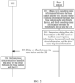
- FIG. 2 is a flowchart of a time synchronization method according to an embodiment of this application. The method includes the following steps.
- Step 201 A base station obtains first round-trip time information between the base station and a UE, second round-trip time information between the base station and a benchmark device, and third round-trip time information between the benchmark device and the UE.
- the benchmark device is a device configured to assist in determining delays between the base station and the UE, in other words, the delays between the base station and the UE can be accurately determined with assistance of the benchmark device, where the delays specifically include a delay from the base station to the UE and a delay from the UE to the base station.
- the benchmark device can further assist in determining delays between the base station and the benchmark device and delays between the benchmark device and the UE.
- the benchmark device may be another UE (referred to as a benchmark UE) or another base station (referred to as a benchmark base station).
- a benchmark UE another UE
- a benchmark base station another base station
- the first round-trip time information indicates time of receiving and sending packets between the base station and the UE, and the first round-trip time information includes time at which the base station sends a packet and time at which the packet arrives at the UE, and further includes time at which the UE sends a packet and time at which the packet arrives at the base station.
- the second round-trip time information indicates time of receiving and sending packets between the base station and the benchmark device, and the second round-trip time information includes time at which the base station sends a packet and time at which the packet arrives at the benchmark device, and further includes time at which the benchmark device sends a packet and time at which the packet arrives at the base station.
- the third round-trip time information indicates time of receiving and sending packets between the benchmark device and the UE, and the third round-trip time information includes time at which the benchmark device sends a packet and time at which the packet arrives at the UE, and further includes time at which the UE sends a packet and time at which the packet arrives at the benchmark device.
- the base station may further send the identification information of the UE and the indication information to the benchmark device, to trigger the benchmark device to obtain the third round-trip time information between the benchmark device and the UE. Then, the benchmark device sends the third round-trip time information to the UE.
- Step 202 The base station determines the delay from the base station to the UE based on the first round-trip time information, the second round-trip time information, and the third round-trip time information.
- the delay from the base station to the UE is duration taken by a packet sent by the base station to arrive at the UE, namely, a time difference between a time at which the base station sends the packet and a time at which the packet arrives at the UE.
- the base station may determine the delay from the base station to the UE based on a target function, the first round-trip time information, the second round-trip time information, and the third round-trip time information. For example, the base station first determines restrictive conditions of the target function based on the first round-trip time information, the second round-trip time information, and the third round-trip time information, and then determines the delay from the base station to the UE based on the restrictive conditions of the target function and the target function.
- the target function is preconfigured in the base station, or is from an AF or a TSCTSF.
- the target function is a minimum value function or a minimum mean square error function that uses the restrictive conditions as solution space preferences.
- the base station constructs a solution space based on the restrictive conditions, and obtains a minimum value or a minimum mean square error of the target function from the solution space.
- Step 203 The base station sends the delay or an offset between the base station and the UE to the UE.
- time synchronization means keeping time of the UE the same as that of the base station.
- the offset is determined based on the first round-trip time information and the delay.
- the base station When the base station sends the delay to the UE, the base station further sends time of the base station while sending the delay.
- Step 204 The UE performs time synchronization based on the delay or the offset between the base station and the UE.
- the UE uses a sum of the time of the base station and the delay as current time of the UE to implement time synchronization.
- the UE If receiving the offset from the base station, the UE updates time of the UE to a sum of time at which the UE receives the offset and the offset. For example, if the UE receives the offset at a moment T, the UE uses a sum of T and the offset as current time of the UE.
- the base station may accurately determine the offset or the delay, and send the offset or the delay to the UE, and the UE performs time synchronization based on the offset or the delay. This can reduce impact of path asymmetry on time provision of the base station, implement accurate time synchronization between the UE and the base station, and help improve a communication capability of the UE.
- FIG. 3(a) and FIG. 3(b) the following provides a specific implementation of the embodiment in FIG. 2 .
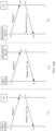
- FIG. 3(a) is an example diagram of delays between devices according to an embodiment of this application.
- a is the delay from the base station to the UE
- b is the delay from the UE to the base station
- c is a delay from the base station to the benchmark device
- d is a delay from the benchmark device to the base station
- e is a delay from the benchmark device to the UE
- f is a delay from the UE to the benchmark device.
- the benchmark device may be another UE or another base station.
- Wireless communication is established between the UE and the base station, and the UE communicates with the base station in an air interface manner.
- wireless communication may be established between the UE and the benchmark device, or wired communication may be established through an optical fiber.
- the benchmark device is the base station
- wireless communication may be established between the base station and the benchmark device, or wired communication may be established through an optical fiber.
- FIG. 3(b) is an example diagram of round-trip time (Round-Trip Time, RTT) operations according to an embodiment of this application.
- the embodiment in FIG. 3(b) is implemented with reference to the embodiment in FIG. 3(a) , and includes the following three parts.
- an RTT operation between the base station and the UE is as follows.
- an RTT operation between the benchmark device and the UE is as follows.
- the benchmark device sends a packet 5 to the UE at the moment t9.
- the benchmark device may obtain four time points, that is, t9 to t12, and then the benchmark device sends the four time points to the base station, where t9 to t12 are referred to as the third round-trip time information between the benchmark device and the UE.
- the foregoing target function may be solved by using the foregoing four restrictive conditions, to obtain optimal solutions of a, b, c, d, e, and f.
- the benchmark device is the another UE (namely, the benchmark UE), and the UE is connected to the benchmark device (namely, the benchmark UE) through the optical fiber
- a represents a measurement value of the delay from the base station to the UE
- a' represents an actual value of the delay from the base station to the UE
- b represents a measurement value of the delay from the UE to the base station
- b' represents an actual value of the delay from the UE to the base station.
- the base station may obtain an accurate value of offset1 based on the values of a and b and the foregoing formula (3). Then, the base station sends the value of offset1 to the UE. Assuming that the UE receives offset1 at a moment T1, the UE updates the time of the UE to T1+offset1, to implement accurate time synchronization between the UE and the base station.
- the base station may send the time (represented by T2) of the base station and the value of a to the UE.
- the UE After receiving T2 and the value of a, the UE updates the time of the UE to T2+a, to implement accurate time synchronization between the UE and the base station.
- the delay a from the base station to the UE is obtained through accurate calculation
- the delay b from the UE to the base station is obtained through calculation
- offset1 is obtained through accurate calculation, so that accurate time synchronization of the UE can be implemented.
- FIG. 4A and FIG. 4B and FIG. 5A and FIG. 5B the following describes the embodiment in FIG. 2 in detail.
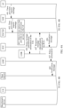
- FIG. 4A and FIG. 4B are a schematic flowchart of a time synchronization method according to an embodiment of this application.
- an AF requests to provide a time provision service for a UE.
- the method includes the following steps.
- Step 401 The AF sends a time provision request message to an NEF, where the time provision request message includes identification information of the UE, identification information of a benchmark device, and indication information.
- the UE is a time provision object, to be specific, the time provision service is to be provided for the UE.
- the benchmark device is a UE other than the time provision object; or the benchmark device is a base station but not a base station that provides the time provision service for the UE.
- the benchmark device provides an auxiliary function for accurate time provision of the UE.
- the indication information indicates to perform a time provision error elimination operation.
- the time provision request message is an Nnef_TimeSynchronization_ASTICreate/Update/Delete message.
- Step 402 The NEF sends the time provision request message to a TSCTSF, where the time provision request message includes the identification information of the UE, the identification information of the benchmark device, and the indication information.
- the NEF After receiving the time provision request message from the AF, the NEF authenticates the AF. If the authentication succeeds, the NEF sends the time provision request message to the TSCTSF.
- the identification information of the UE, the identification information of the benchmark device, and the indication information in the time provision request message sent by the NEF are from the AF.
- the time provision request message is an Ntsetsf_TimeSynchronization_ASTICreate/Update/Delete message.
- Step 403 The TSCTSF selects a base station that provides the time provision service for the UE.
- the TSCTSF selects, from a plurality of base stations based on distribution information of the base stations, the base station that provides the time provision service for the UE.
- the benchmark device is a base station
- the benchmark device and the base station that provides the time provision service for the UE are different base stations.
- Step 404 The TSCTSF sends a query message to a UDR, where the query message includes the identification information of the UE, and the query message is for requesting to obtain a PCF that provides a service for the UE.
- the query message is an Nudr_DM_Create/Update/Delete request message.
- Step 405 The UDR sends a response message to the TSCTSF, where the response message includes identification information of the PCF.
- the response message is an Nudr_DM_Create/Update/Delete response message.
- Step 406 The TSCTSF sends a notification message to the PCF, where the notification message includes the identification information of the UE, identification information of the base station, the identification information of the benchmark device, and the indication information.
- the base station is the base station that is selected by the TSCTSF to provide the time provision service for the UE, and the identification information of the UE, the identification information of the benchmark device, and the indication information are received by the TSCTSF in the foregoing step 402.
- Step 407 The PCF sends policy information to an AMF, where the policy information includes the identification information of the UE, the identification information of the base station, the identification information of the benchmark device, and the indication information.
- the identification information of the UE, the identification information of the base station, the identification information of the benchmark device, and the indication information in the policy information are received by the PCF from the TSCTSF.
- the response message in step 405 carries identification information of the AMF.
- Step 406 and step 407 do not need to be performed, but the TSCTSF sends the identification information of the UE, identification information of the base station, the identification information of the benchmark device, and the indication information to the AMF.
- Step 408 The AMF sends the notification message to the base station, where the notification message includes the identification information of the UE, the identification information of the benchmark device, and the indication information.
- the identification information of the UE, the identification information of the benchmark device, and the indication information in the notification message are received by the AMF from the PCF or the TSCTSF.
- Step 409a The AMF sends the notification message to the benchmark device, where the notification message includes the identification information of the UE, the identification information of the base station, and the indication information.
- the identification information of the UE, the identification information of the base station, and the indication information in the notification message are received by the AMF from the PCF or the TSCTSF.
- Step 409b The base station sends the notification message to the benchmark device, where the notification message includes the identification information of the UE, the identification information of the base station, and the indication information.
- the identification information of the UE, the identification information of the base station, and the indication information in the notification message are received by the base station from the AMF.
- step 409a or step 409b is performed, in other words, step 409a or step 409b is performed.
- Step 410a The base station performs an RTT operation with the UE, and the base station records four time points.
- the four time points recorded by the base station are t1, t2, t3, and t4.
- Step 410b The base station performs an RTT operation with the benchmark device, and the base station records four time points.
- the four time points recorded by the base station are t5, t6, t7, and t8.
- Step 410c The benchmark device performs an RTT operation with the UE, and the benchmark device records four time points and sends the four time points to the base station.
- a sequence of step 410a, step 410b, and step 410c is not limited.
- the base station calculates the offset based on t1, t2, t3, t4, t5, t6, t7, t8, t9, t10, t11, and t12. For a specific calculation method, refer to the descriptions of the embodiment in FIG. 2 .
- a target function used by the base station to calculate the offset may be preconfigured in the base station, or may be from the AF.
- the target function or information indicating the target function is carried in step 401 and step 402 and step 406 to step 408.
- Step 412 The base station sends the offset to the UE.
- Step 413 The UE performs time synchronization based on the offset.
- the UE may update time of the UE to a sum of a time point at which the offset is received and the offset. For example, if the UE receives the offset at a moment T, and a value of the offset is represented by K, the UE updates the time of the UE to T+K.
- step 411 to step 413 are not performed, but the following is performed:
- the base station calculates a delay (delay) from the base station to the UE, and then the base station sends T1 and the delay to the UE, where T1 is time that is based on a clock on the base station and at which the base station sends the delay. Then, the UE updates time of the UE to a sum of T1 and the delay.
- the TSCTSF may send, to the NEF, a time provision response message for notifying successful time provision, and then the NEF sends, to the AF, the time provision response message for notifying successful time provision.
- the AF requests the time provision service for the UE.
- the TSCTSF selects the base station that provides the time provision service for the UE.
- the base station performs the time provision error elimination operation, determines an accurate offset, and sends the offset to the UE.
- the UE performs time synchronization based on the offset.
- the method can reduce impact of path asymmetry on time provision of the base station, implement accurate time synchronization between the UE and the base station, and help improve a communication capability of the UE.
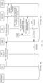
- FIG. 5A and FIG. 5B are a schematic flowchart of a time synchronization method according to an embodiment of this application.
- a UE actively requests to provide a time provision service for the UE.
- the method includes the following steps.
- Step 501 The UE sends a time provision request message to an AMF, where the time provision request message includes identification information of the UE, identification information of a benchmark device, and indication information.
- the UE is a time provision object, to be specific, the time provision service is to be provided for the UE.
- the benchmark device is a UE other than the time provision object; or the benchmark device is a base station but not a base station that provides the time provision service for the UE.
- the benchmark device provides an auxiliary function for accurate time provision of the UE.
- the indication information indicates to perform a time provision error elimination operation.
- the time provision request message is an NAS_TimeSynchronization_ASTICreate/Update/Delete message.
- Step 502 The AMF sends the time provision request message to a TSCTSF, where the time provision request message includes the identification information of the UE, the identification information of the benchmark device, and the indication information.
- the identification information of the UE, the identification information of the benchmark device, and the indication information in the time provision request message sent by the AMF are from the UE.
- the time provision request message is an Ntsetsf_TimeSynchronization_ASTICreate/Update/Delete message.
- Step 503 The TSCTSF sends a request message to a UDM, where the request message includes the identification information of the UE.
- the request message is used to query whether the UE is authorized to be provided with the time provision service.
- Step 504 The UDM sends a response message to the TSCTSF.
- the response message indicates that the UE is authorized to be provided with the time provision service.
- Step 503 and step 504 are optional steps.
- step 505 to step 515 refer to step 403 to step 413.
- step 513 to step 515 the following operation is performed:
- the base station calculates a delay (delay) from the base station to the UE, and then the base station sends T1 and the delay to the UE, where T1 is time that is based on a clock on the base station and at which the base station sends the delay.
- the UE updates time of the UE to a sum of T1 and the delay.
- the TSCTSF may send, to the AMF, a time provision response message for notifying successful time provision, and then the AMF sends, to the UE, the time provision response message for notifying successful time provision.
- the UE actively requests the time provision service.
- the TSCTSF selects the base station that provides the time provision service for the UE.
- the base station performs the time provision error elimination operation, determines an accurate offset, and sends the offset to the UE.
- the UE performs time synchronization based on the offset.
- the method can reduce impact of path asymmetry on time provision of the base station, implement accurate time synchronization between the UE and the base station, and help improve a communication capability of the UE.
- the TSCTSF selects the base station that provides the time provision service for the UE.
- the TSCTSF may not select the base station that provides the time provision service for the UE, but sends a first notification message to an AMF/PCF, where the first notification message includes identification information of UE, identification information of a benchmark device, indication information, identification information of a plurality of base stations, and capability information of the plurality of base stations.
- the capability information indicates whether the base station can provide time, and the indication information indicates to perform a time provision error elimination operation.
- the AMF/PCF selects, based on location information of the plurality of base stations and the capability information of the plurality of base stations, a base station that provides a time provision service for the UE. Then, the AMF/PCF sends a second notification message to the selected base station, where the second notification message includes the identification information of the UE, the identification information of the benchmark device, and the indication information.
- That the AMF/PCF selects, based on location information of the plurality of base stations and the capability information of the plurality of base stations, a base station that provides a time provision service for the UE may be that, for example, the AMF/PCF selects, from the plurality of base stations based on the capability information of the plurality of base stations, at least one base station that can provide time, and then selects, from the at least one base station based on location information of the at least one base station, a base station that provides a time provision service for the UE.
- an access network device includes a corresponding hardware structure and/or software module for performing each function.
- a clock management network element includes a corresponding hardware structure and/or software module for performing each function.
- the units and method steps in the examples described with reference to embodiments disclosed in this application may be implemented by hardware or a combination of hardware and computer software. Whether a function is performed by hardware or hardware driven by computer software depends on particular application scenarios and design constraint conditions of the technical solutions.
- FIG. 6 and FIG. 7 each are a diagram of a structure of a possible communication apparatus according to an embodiment of this application. These communication apparatuses may be configured to implement functions of the access network device, the clock management network element, the mobility management network element, or the policy control network element in the foregoing method embodiments. Therefore, beneficial effects of the foregoing method embodiments can also be implemented.
- the communication apparatus may be an access network device, a clock management network element, a mobility management network element, or a policy control network element, or may be a module in an access network device, a module in a clock management network element, a module in a mobility management network element, or a module in a policy control network element.
- the communication apparatus 600 includes a processing unit 610 and a transceiver unit 620.
- the communication apparatus 600 is configured to implement functions of the access network device or the terminal device in the foregoing method embodiments.
- the transceiver unit 620 may be configured to implement a corresponding communication function.
- the transceiver unit 620 may also be referred to as a communication interface or a communication unit.
- the processing unit 610 may be configured to implement a corresponding processing function.
- the communication apparatus 600 further includes a storage unit.
- the storage unit may be configured to store instructions and/or data.
- the processing unit 610 may read the instructions and/or the data in the storage unit, so that the communication apparatus 600 implements actions of the access network device (such as the base station), the clock management network element (such as the TSCTSF), the mobility management network element (such as the AMF), or the policy control network element (such as the PCF) in the foregoing method embodiments.
- the access network device such as the base station
- the clock management network element such as the TSCTSF
- the mobility management network element such as the AMF
- the policy control network element such as the PCF
- the processing unit 610 is configured to: obtain first round-trip time information between the access network device and the terminal device, second round-trip time information between the access network device and a benchmark device, and third round-trip time information between the benchmark device and the terminal device; and determine a delay from the access network device to the terminal device based on the first round-trip time information, the second round-trip time information, and the third round-trip time information.
- the transceiver unit 620 is configured to send the delay or an offset between the access network device and the terminal device to the terminal device, where the delay or the offset is used for time synchronization of the terminal device, and the offset is determined based on the first round-trip time information and the delay.
- the transceiver unit 620 is further configured to receive a notification message, where the notification message includes identification information of the benchmark device, identification information of the terminal device, and indication information, and the indication information indicates to perform a time provision error elimination operation.
- the transceiver unit 620 is further configured to send the identification information of the terminal device and the indication information to the benchmark device.
- the processing unit 610 is specifically configured to determine the delay from the access network device to the terminal device based on a target function, the first round-trip time information, the second round-trip time information, and the third round-trip time information.
- the target function is preconfigured in the access network device, or is from an application function network element or a clock management network element.
- the processing unit 610 is specifically configured to: determine restrictive conditions of the target function based on the first round-trip time information, the second round-trip time information, and the third round-trip time information; and determine the delay from the access network device to the terminal device based on the restrictive conditions of the target function and the target function.
- the target function is a minimum value function or a minimum mean square error function that uses the restrictive conditions as solution space preferences.
- the target function is min(abs(a-b)+abs(d-c)+abs(f-e)) or min(min(abs(a-b)+abs(d-c)+abs(f-e))), where min() represents a minimum value function, and abs() represents an absolute value function.
- the target function is MSE(a-a'), MSE(b-b'), or MSE((a-a')+(b-b')), where MSE() represents a minimum mean square error function.
- the target function is min(abs(a-b)+abs(d-c)), where min() represents a minimum value function, and abs() represents an absolute value function.
- the target function is min(abs(a-b)+abs(f-e)), where min() represents a minimum value function, and abs() represents an absolute value function.
- the transceiver unit 620 is configured to receive a time provision request message, where the time provision request message includes identification information of a terminal device, identification information of a benchmark device, and indication information, and the indication information indicates to perform a time provision error elimination operation.
- the processing unit 610 is configured to select an access network device that provides a time provision service for the terminal device.
- the transceiver unit 620 is further configured to send a notification message to the policy control network element or the mobility management network element, where the notification message includes the identification information of the terminal device, the identification information of the benchmark device, identification information of the access network device, and the indication information.
- the transceiver unit 620 is further configured to: send a request message to a unified data management network element, where the request message includes the identification information of the terminal device, and the request message is used to query whether the terminal device is authorized to be provided with a time provision service; and receive a response message from the unified data management network element, where the response message indicates that the terminal device is authorized to be provided with the time provision service.
- the transceiver unit 620 is specifically configured to receive the time provision request message from the terminal device or an application function network element.
- the transceiver unit 620 is configured to receive a first notification message, where the first notification message includes identification information of a terminal device, identification information of a benchmark device, indication information, identification information of a plurality of access network devices, and capability information of the plurality of access network devices, the capability information indicates whether the access network device can provide time, and the indication information indicates to perform a time provision error elimination operation.
- the processing unit 610 is configured to select, based on location information of the plurality of access network devices and the capability information of the plurality of access network devices, an access network device that provides a time provision service for the terminal device.
- the transceiver unit 620 is further configured to send a second notification message to the selected access network device, where the second notification message includes the identification information of the terminal device, the identification information of the benchmark device, and the indication information.
- the processing unit 610 is specifically configured to: select, from the plurality of access network devices based on the capability information of the plurality of access network devices, at least one access network device that can provide time; and select, based on location information of the at least one access network device, an access network device that provides a time provision service for the terminal device.
- processing unit 610 and the transceiver unit 620 directly refer to related descriptions in the foregoing method embodiments. Details are not described herein again.
- the communication apparatus 700 shown in FIG. 7 includes a processor 710 and an interface circuit 720.
- the processor 710 and the interface circuit 720 are coupled to each other.
- the interface circuit 720 may be a transceiver or an input/output interface.
- the communication apparatus 700 may further include a memory 730, configured to store instructions executed by the processor 710, or store input data required by the processor 710 to run instructions, or store data generated after the processor 710 runs instructions.
- the processor 710 is configured to implement a function of the processing unit 610
- the interface circuit 720 is configured to implement a function of the transceiver unit 620.
- the processor in embodiments of this application may be a central processing unit (central processing unit, CPU), or may be another general-purpose processor, a digital signal processor (digital signal processor, DSP), an application-specific integrated circuit (application-specific integrated circuit, ASIC), a field programmable gate array (field programmable gate array, FPGA) or another programmable logic device, a transistor logic device, a hardware component, or any combination thereof.
- the general-purpose processor may be a microprocessor or any regular processor or the like.
- the method steps in embodiments of this application may be implemented in a hardware manner, or may be implemented in a manner of executing software instructions by the processor.
- the software instructions may include a corresponding software module.
- the software module may be stored in a random access memory, a flash memory, a read-only memory, a programmable read-only memory, an erasable programmable read-only memory, an electrically erasable programmable read-only memory, a register, a hard disk, a removable hard disk, a CD-ROM, or any other form of storage medium well-known in the art.
- a storage medium is coupled to a processor, so that the processor can read information from the storage medium and write the information into the storage medium.
- the storage medium may be a component of the processor.
- the processor and the storage medium may be disposed in the ASIC.
- the processor and the storage medium may exist in a base station or terminal as discrete components.
- All or some of the foregoing embodiments may be implemented by using software, hardware, firmware, or any combination thereof.
- the software is used to implement the embodiments, all or some of the embodiments may be implemented in a form of a computer program product.
- the computer program product includes one or more computer programs or instructions. When the computer programs or instructions are loaded and executed on a computer, the procedures or functions in embodiments of this application are all or partially performed.
- the computer may be a general-purpose computer, a dedicated computer, a computer network, a base station, a UE, or another programmable apparatus.
- the computer programs or instructions may be stored in a computer-readable storage medium, or may be transmitted from a computer-readable storage medium to another computer-readable storage medium.
- the computer programs or instructions may be transmitted from a website, computer, server, or data center to another website, computer, server, or data center in a wired or wireless manner.
- the computer-readable storage medium may be any usable medium that can be accessed by the computer, or a data storage device, for example, a server or a data center, integrating one or more usable media.
- the usable medium may be a magnetic medium, for example, a floppy disk, a hard disk, or a magnetic tape; or may be an optical medium, for example, a digital video disc; or may be a semiconductor medium, for example, a solid-state drive.
- the computer-readable storage medium may be a volatile or non-volatile storage medium, or may include two types of storage media: a volatile storage medium and a non-volatile storage medium.
- "at least one” means one or more, and "a plurality of” means two or more.
- "And/or” describes an association relationship between associated objects, and indicates that three relationships may exist. For example, A and/or B may indicate the following three cases: Only A exists, both A and B exist, and only B exists, where A and B may be singular or plural.
- the character “/” indicates an “or” relationship between the associated objects. In the formula in this application, the character “/” indicates a "division" relationship between the associated objects.
Landscapes
- Engineering & Computer Science (AREA)
- Computer Networks & Wireless Communication (AREA)
- Signal Processing (AREA)
- Mobile Radio Communication Systems (AREA)
Applications Claiming Priority (2)
| Application Number | Priority Date | Filing Date | Title |
|---|---|---|---|
| CN202210594963.3A CN117177347A (zh) | 2022-05-28 | 2022-05-28 | 一种时间同步方法及通信装置 |
| PCT/CN2023/075611 WO2023231450A1 (fr) | 2022-05-28 | 2023-02-13 | Procédé de synchronisation temporelle et appareil de communication |
Publications (2)
| Publication Number | Publication Date |
|---|---|
| EP4529301A1 true EP4529301A1 (fr) | 2025-03-26 |
| EP4529301A4 EP4529301A4 (fr) | 2025-09-17 |
Family
ID=88928667
Family Applications (1)
| Application Number | Title | Priority Date | Filing Date |
|---|---|---|---|
| EP23814649.2A Pending EP4529301A4 (fr) | 2022-05-28 | 2023-02-13 | Procédé de synchronisation temporelle et appareil de communication |
Country Status (4)
| Country | Link |
|---|---|
| US (1) | US20250088988A1 (fr) |
| EP (1) | EP4529301A4 (fr) |
| CN (1) | CN117177347A (fr) |
| WO (1) | WO2023231450A1 (fr) |
Families Citing this family (3)
| Publication number | Priority date | Publication date | Assignee | Title |
|---|---|---|---|---|
| CN120129041A (zh) * | 2023-12-09 | 2025-06-10 | 华为技术有限公司 | 授时方法、授时装置、电子设备及存储介质 |
| CN120475450A (zh) * | 2024-02-07 | 2025-08-12 | 华为技术有限公司 | 一种通信方法及装置 |
| CN118828846A (zh) * | 2024-03-19 | 2024-10-22 | 中移(上海)信息通信科技有限公司 | 授时方法、基站、终端、存储介质和计算机程序产品 |
Family Cites Families (5)
| Publication number | Priority date | Publication date | Assignee | Title |
|---|---|---|---|---|
| EP1701564A4 (fr) * | 2003-12-10 | 2012-11-07 | Nec Corp | Procede de mesure de difference de temps de transmission et systeme associe |
| JP6384697B2 (ja) * | 2014-05-30 | 2018-09-05 | 華為技術有限公司Huawei Technologies Co.,Ltd. | 同期方法、同期装置、および基地局 |
| CN108964819B (zh) * | 2017-05-19 | 2019-11-26 | 华为技术有限公司 | 一种时钟调整、时钟偏差计算方法、设备及系统 |
| US11362921B2 (en) * | 2017-12-19 | 2022-06-14 | Qualcomm Incorporated | Systems and methods for multiple round trip time (RTT) estimation in wireless networks |
| CN112636858B (zh) * | 2020-12-11 | 2022-03-18 | 北京邮电大学 | 多网络设备协作的授时方法、系统、电子设备及介质 |
-
2022
- 2022-05-28 CN CN202210594963.3A patent/CN117177347A/zh active Pending
-
2023
- 2023-02-13 EP EP23814649.2A patent/EP4529301A4/fr active Pending
- 2023-02-13 WO PCT/CN2023/075611 patent/WO2023231450A1/fr not_active Ceased
-
2024
- 2024-11-26 US US18/960,651 patent/US20250088988A1/en active Pending
Also Published As
| Publication number | Publication date |
|---|---|
| US20250088988A1 (en) | 2025-03-13 |
| CN117177347A (zh) | 2023-12-05 |
| EP4529301A4 (fr) | 2025-09-17 |
| WO2023231450A1 (fr) | 2023-12-07 |
Similar Documents
| Publication | Publication Date | Title |
|---|---|---|
| EP4529301A1 (fr) | Procédé de synchronisation temporelle et appareil de communication | |
| US20220256451A1 (en) | Incompatible network slices support and management | |
| US20240365265A1 (en) | Time service method, communication apparatus, and communication system | |
| EP3681182B1 (fr) | Procédé, appareil et dispositif de détermination d'état de dispositif terminal | |
| WO2023213177A1 (fr) | Procédé et appareil de communication | |
| CN115942362B (zh) | 一种业务感知方法、通信装置及通信系统 | |
| US20250016274A1 (en) | Communication method and apparatus | |
| WO2023045741A1 (fr) | Procédé et appareil de positionnement, et support de stockage lisible | |
| WO2023179238A1 (fr) | Procédé de synchronisation, appareil de communication et système de communication | |
| WO2023104123A1 (fr) | Appareil et procédé de communication, et dispositif | |
| US20250024390A1 (en) | Communication Method and Apparatus | |
| EP4564712A1 (fr) | Procédé et appareil de garantie de synchronisation d'horloge | |
| US20240334241A1 (en) | Detection method, communication apparatus, and communication system | |
| WO2024208017A1 (fr) | Procédé de communication, appareil de communication et système de communication | |
| WO2023125392A1 (fr) | Procédé et appareil de communication | |
| WO2024254749A1 (fr) | Procédé de réception d'informations, procédé de vérification de terminal et procédé d'envoi d'informations, et appareil, dispositif et support de stockage | |
| US20250365603A1 (en) | Communication method, communication apparatus, and communication system | |
| WO2023231465A1 (fr) | Procédé de synchronisation temporelle, appareil de communication et système de communication | |
| WO2023051620A1 (fr) | Procédé de communication, appareil de communication et système de communication | |
| CN117295145A (zh) | 一种检测时钟的方法及通信装置 | |
| EP4561149A1 (fr) | Procédé de gestion de tranche de réseau, appareil de communication et système de communication | |
| WO2025066165A1 (fr) | Procédé et appareil de communication | |
| US20240023182A1 (en) | Handling the unknown rrc establishment cause value in nr | |
| WO2023061207A1 (fr) | Procédé de communication, appareil de communication et système de communication | |
| CN118869615A (zh) | 一种通信方法、通信装置及通信系统 |
Legal Events
| Date | Code | Title | Description |
|---|---|---|---|
| STAA | Information on the status of an ep patent application or granted ep patent |
Free format text: STATUS: THE INTERNATIONAL PUBLICATION HAS BEEN MADE |
|
| PUAI | Public reference made under article 153(3) epc to a published international application that has entered the european phase |
Free format text: ORIGINAL CODE: 0009012 |
|
| STAA | Information on the status of an ep patent application or granted ep patent |
Free format text: STATUS: REQUEST FOR EXAMINATION WAS MADE |
|
| 17P | Request for examination filed |
Effective date: 20241217 |
|
| AK | Designated contracting states |
Kind code of ref document: A1 Designated state(s): AL AT BE BG CH CY CZ DE DK EE ES FI FR GB GR HR HU IE IS IT LI LT LU LV MC ME MK MT NL NO PL PT RO RS SE SI SK SM TR |
|
| DAV | Request for validation of the european patent (deleted) | ||
| DAX | Request for extension of the european patent (deleted) | ||
| A4 | Supplementary search report drawn up and despatched |
Effective date: 20250818 |
|
| RIC1 | Information provided on ipc code assigned before grant |
Ipc: H04W 56/00 20090101AFI20250811BHEP |