EP4529341A1 - Interaktionsverfahren und zugehörige vorrichtung - Google Patents
Interaktionsverfahren und zugehörige vorrichtung Download PDFInfo
- Publication number
- EP4529341A1 EP4529341A1 EP23806790.4A EP23806790A EP4529341A1 EP 4529341 A1 EP4529341 A1 EP 4529341A1 EP 23806790 A EP23806790 A EP 23806790A EP 4529341 A1 EP4529341 A1 EP 4529341A1
- Authority
- EP
- European Patent Office
- Prior art keywords
- parallel
- dus
- information
- sent
- receiving
- Prior art date
- Legal status (The legal status is an assumption and is not a legal conclusion. Google has not performed a legal analysis and makes no representation as to the accuracy of the status listed.)
- Pending
Links
Images



Classifications
-
- H—ELECTRICITY
- H04—ELECTRIC COMMUNICATION TECHNIQUE
- H04W—WIRELESS COMMUNICATION NETWORKS
- H04W76/00—Connection management
- H04W76/10—Connection setup
- H04W76/19—Connection re-establishment
-
- H—ELECTRICITY
- H04—ELECTRIC COMMUNICATION TECHNIQUE
- H04W—WIRELESS COMMUNICATION NETWORKS
- H04W36/00—Hand-off or reselection arrangements
- H04W36/08—Reselecting an access point
-
- H—ELECTRICITY
- H04—ELECTRIC COMMUNICATION TECHNIQUE
- H04W—WIRELESS COMMUNICATION NETWORKS
- H04W36/00—Hand-off or reselection arrangements
- H04W36/0005—Control or signalling for completing the hand-off
- H04W36/0011—Control or signalling for completing the hand-off for data sessions of end-to-end connection
- H04W36/0033—Control or signalling for completing the hand-off for data sessions of end-to-end connection with transfer of context information
-
- H—ELECTRICITY
- H04—ELECTRIC COMMUNICATION TECHNIQUE
- H04W—WIRELESS COMMUNICATION NETWORKS
- H04W36/00—Hand-off or reselection arrangements
- H04W36/0005—Control or signalling for completing the hand-off
- H04W36/0055—Transmission or use of information for re-establishing the radio link
- H04W36/0064—Transmission or use of information for re-establishing the radio link of control information between different access points
-
- H—ELECTRICITY
- H04—ELECTRIC COMMUNICATION TECHNIQUE
- H04W—WIRELESS COMMUNICATION NETWORKS
- H04W76/00—Connection management
- H04W76/20—Manipulation of established connections
- H04W76/27—Transitions between radio resource control [RRC] states
-
- H—ELECTRICITY
- H04—ELECTRIC COMMUNICATION TECHNIQUE
- H04W—WIRELESS COMMUNICATION NETWORKS
- H04W88/00—Devices specially adapted for wireless communication networks, e.g. terminals, base stations or access point devices
- H04W88/08—Access point devices
- H04W88/085—Access point devices with remote components
Definitions
- the present disclosure relates to the field of interaction technologies and, in particular, to an interaction method and related devices.
- one base station includes one CU (Centralized Unit, CU) and a plurality of DUs (Distributed Unit, DU).
- CU Centralized Unit
- DU Distributed Unit
- a plurality of DUs need to interact with the CU.
- the way in which the plurality of DUs interact with the CU is as follows: after the interaction between one DU and the CU is completed, the interaction between the next DU and the CU is to be completed. Assuming that an interaction time between the DU and the CU is T, an interaction time between one DU and the CU is 2T, and if the number of the DUs interacting with the CU is N, the interaction time between the plurality of DUs and the CU is 2NT.
- the present disclosure provides an interaction method and related devices, so as to solve the problem of relatively low efficiency of achieving the objective of an interaction scenario between a plurality of DUs and a CU.
- the present disclosure provides an interaction method, applied to a centralized unit entity, and including:
- the second information corresponding to the first DU in parallel further including:
- the second information is an RRC reconfiguration message
- the method further includes: receiving an RRC reconfiguration completion message sent in parallel by each first DU.
- the plurality of first DUs are DUs currently accessed by the UE, and the sending, to each first DU, the second information corresponding to the first DU in parallel, the method further includes:
- the present disclosure further provides an interaction method, applied to a distributed unit entity, and including:
- the present disclosure further provides an interaction method, applied to user equipment, and including: sending an indication message to a plurality of distributed unit entities DUs accessed by a user equipment, where the indication message is used to instruct the plurality of DUs to send information to a centralized unit entity CU in parallel.
- the present disclosure further provides a distributed unit entity, including: a memory, a transceiver and a processor; where the memory is configured to store a computer program; the transceiver is configured to receive and send data under a control of the processor; and the processor is configured to read the computer program in the memory and perform the following operations:
- the present disclosure further provides a distributed unit entity, including:
- the present disclosure further provides a user equipment, including: a third sending unit, configured to send an indication message to a plurality of distributed unit entities DUs accessed by a user equipment, where the indication message is used to instruct the plurality of DUs to send information to a centralized unit entity CU in parallel.
- a third sending unit configured to send an indication message to a plurality of distributed unit entities DUs accessed by a user equipment, where the indication message is used to instruct the plurality of DUs to send information to a centralized unit entity CU in parallel.
- the present disclosure further provides a processor-readable storage medium, where the processor-readable storage medium stores a computer program, and the computer program is used to enable the processor to execute the above method.
- the term "and/or" describes an association relationship between associated objects, and indicates that three relationships may exist.
- a and/or B may indicate three cases: A exists separately, A and B exist simultaneously, and B exists separately.
- the character '/' generally indicates an 'or' relationship between the associated objects.
- the method and the apparatus involved in the present disclosure are based on the same application concept, and since the principle of the method and the apparatus for solving the problem is similar, the implementation of the apparatus and the method can be referred to each other, and redundant description will be omitted.
- the applicable system may be a global system of mobile communication (global system of mobile communication, GSM), a code division multiple access (code division multiple access, CDMA) system, and a wideband code division multiple access (wideband code division multiple access, WCDMA) general packet radio service (general packet radio service, GPRS) system, a long term evolution (long term evolution, LTE) system, an LTE frequency division duplex (frequency division duplex, FDD) system, an LTE time division duplex (time division duplex, TDD) system, a long term evolution advanced (long term evolution advanced, LTE-A) system, a universal mobile telecommunication system (universal mobile telecommunication system, UMTS), a worldwide interoperability for microwave access (worldwide interoperability for microwave access, WiMAX) system, a 5G new radio (New Radio NR) system, etc. All these systems include a terminal device and a network device.
- GSM global system of mobile communication
- CDMA code division multiple access
- WCDMA wideband code division multiple access
- the terminal device involved in the embodiments of the present disclosure may refer to a device providing voice and/or data connectivity for a user, a handheld device having a wireless connection function, or other processing devices connected to a wireless modem, etc.
- the name of the terminal device may also be different, for example, in the 5G system, a terminal device may be referred to as user equipment (User Equipment, UE).
- a wireless terminal device may communicate with one or more core networks (core network, CN) via radio access network (radio access network, RAN).
- core network CN
- radio access network radio access network
- the wireless terminal device may be a mobile terminal device, such as a mobile phone (or referred to as a "cellular" phone) and a computer having the mobile terminal device, and may be, for example, portable, pocket-sized, handheld, computer built-in, or vehicle-mounted mobile apparatuses, which exchange language and/or data with the radio access network, for example, devices such as a personal communication service (Personal Communication Service, PCS) phone, a cordless phone, a session initiated protocol (Session Initiated Protocol, SIP) phone, a wireless local loop (Wireless Local Loop, WLL) station, and personal digital assistant (Personal Digital Assistant PDA), etc.
- PCS Personal Communication Service
- SIP Session Initiated Protocol
- WLL Wireless Local Loop
- PDA Personal Digital Assistant
- the wireless terminal device may also be referred to as a system, a subscriber unit, a subscriber station, a mobile station, a mobile, a remote station, an access point, a remote terminal, an access terminal, a user terminal, a user agent, and a user device, which is not limited in the embodiments of the present disclosure.
- the network device involved in the embodiments of the present disclosure may be a base station.
- the base station may include a plurality of cells providing services for a terminal.
- a base station may also be referred to as an access point, or a device that communicates with a wireless terminal device through one or more sectors over an air interface in access network, or other names.
- the network device can be used to exchange a received air frame with an internet protocol (Internet Protocol, IP) packet, and serves as a router between a wireless terminal device and the rest of the access network, where the rest of the access network may include Internet protocol (IP) communication network.
- IP Internet protocol
- the network device may also coordinate management of attributes of the air interface.
- the network device involved in the embodiments of the present disclosure may be a network device (Base Transceiver Station, BTS) in Global System for Mobile Communications (GSM) or Code Division Multiple Access (CDMA); may also be a network device (NodeB) in Wide-band Code Division Multiple Access (WCDMA); may also be an evolutional network device (evolutional Node B, eNB or e-NodeB) in the long term evolution (LTE) system, a 5G base station (gNB) in a 5G network architecture (next generation system); may also be a home evolved base station (Home evolved Node B, HeNB), a relay node, a femto base station, a pico base station, etc., which are not limited in the embodiments of the present disclosure.
- a network device may include a centralized unit (CU) node and a distributed unit (DU) node.
- the centralized unit and the distributed unit may also be arranged in a geographically separated manner.
- a network device and a terminal device may respectively use one or more antennas to perform multi-input multi-output (Multi Input Multi Output, MIMO) transmission
- MIMO transmission may be single-user MIMO (Single User MIMO, SU-MIMO) or multi-user MIMO (Multiple User MIMO, MU-MIMO).
- the MIMO transmission may be 2D-MIMO, 3D-MIMO, FD-MIMO or massive-MIMO, and may also be diversity transmission, precoding transmission or beam forming transmission, etc.
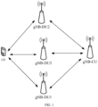
- FIG. 1 is a schematic diagram of an application scenario according to an embodiment of the present disclosure.
- the interaction method provided in this embodiment relates to UE, a plurality of gNB-DUs and a gNB-CU.
- the plurality of gNB-DUs are, for example, gNB-DU1, gNB-DU2, and gNB-DU3.
- UE accesses each gNB-DU, and the CU can send a message to each accessed gNB-DU, where the message is used to instruct each gNB-DU to send a message to the gNB-CU in parallel or in series.
- the parallel sending of the message refers to that the plurality of gNB-DUs send a message to the gNB-CU in the same time period.
- the serial sending of the message refers to that after one gNB-DU among the plurality of gNB-DUs accessed by the UE completes information interaction with the gNB-CU, another gNB-DU accessed by the UE performs information interaction with the gNB-CU again. If the plurality of gNB-DUs send a message to the gNB-CU in parallel, the gNB-CU may also send a message to the plurality of gNB-DUs in parallel.
- the interaction scenarios between the plurality of DUs and the CU involved in the present disclosure include initial access of the UE, inter-mobility of the gNB-DUs, and intra-handover of the gNB-DU.
- the initial access of the UE refers to a scenario in which the UE accesses a plurality of gNB-DUs.
- the inter-mobility of the gNB-DUs refers to that the UE is handed over from a plurality of accessed gNB-DUs to another plurality of gNB-DUs.
- the intra-handover of the gNB-DU refers to that the UE moves from one cell to another cell, and the UE switches from accessing a gNB-DU of a cell before the UE moves to accessing a gNB-DU after the UE moves; or, the intra-handover of the gNB-DU refers to that the gNB-DU accessed by the UE in a cell is handed over to another gNB-DU in the cell.
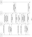
- the initial access of the UE and the inter-mobility of the gNB-DUs involve many flows, and the flows of the two interaction scenarios will be described below.
- the flow of the initial access of UE is as follows.
- the flow of the inter-mobility of the gNB-DUs is as follows.
- the CU After the UE accesses a Source gNB-DU (hereinafter referred to as a source DU for short), the CU sends downlink user data to the UE and the source DU accessed by the UE, and the UE sends downlink user data to the source DU and the CU.
- a source DU for short
- the CU After the UE accesses a Source gNB-DU (hereinafter referred to as a source DU for short), the CU sends downlink user data to the UE and the source DU accessed by the UE, and the UE sends downlink user data to the source DU and the CU.
- FIG. 4 is a schematic flowchart of an interaction method according to an embodiment of the present disclosure, which is applied to a centralized unit entity. The method includes the following steps.
- Step S101 receive first information sent in parallel by a plurality of first distributed unit entities DUs accessed by a user equipment UE.
- the first information may be initial uplink radio resource control information transmitted to the CU by each first DU after the first DU receives an RRC establishment request, and the second information is downlink radio resource control information transmitted to each first DU by the CU.
- the initial uplink radio resource control information includes C-RNTI (temporary identifier) and gNB-DU ID allocated to each first DU by the UE, that is, each first DU sends its own C-RNTI and gNB-DU ID to the CU through first information.
- the initial access of the UE may involve RRC reconfiguration, that is, the second information is an RRC reconfiguration message sent by the CU to the plurality of first DUs, and each first DU sends RRC reconfiguration to the CU.
- the UE sends an RRC reconfiguration completion message to each first DU.
- Each first DU sends the RRC reconfiguration completion message to the CU in parallel, that is, the CU receives an RRC reconfiguration completion message sent by each first DU in parallel.
- Step S201 determine a plurality pieces of first information to be sent to the first DU.
- a first DU accessed by the UE includes DU1, DU2 and DU3, message a of the DU1 carries identifiers 2 and 3, where the message a is a message sent by the DU1 to the DU2 and the DU3.
- message b of the DU2 carries identifiers 1 and 3
- the message b of the DU2 is a message sent to the DU1 and the DU3.
- Message c of the DU3 carries identifiers 1 and 2
- the message c of the DU3 is a message sent to the DU2 and the DU1.
- respective pieces of first information to be sent to the DU1 are message b and message c
- respective pieces first information to be sent to the DU2 are message a and message c
- respective pieces first information to be sent to the DU3 are message a and message b.
- Step S202 determine the second information of the first DU according to the plurality pieces of first information to be sent to the first DU.
- the CU integrates the plurality pieces of first information of the first DU into the second information of the first DU. For example, if respective pieces of first information to be sent to the DU1 are message b and message c, the second information of the DU1 includes the message b and the message c. If respective pieces of first information to be sent to the DU2 are message a and message c, the second information of the DU2 includes the message a and the message c. If respective pieces of first information to be sent to the DU3 are message a and message b, the second information of the DU3 includes the message a and the message b.
- Step S301 receive a context modification response message of the UE sent in parallel by each first DU.
- the first information is an uplink RRC message
- the second information is a context modification request of the UE.
- each first DU After receiving the context modification request of the UE, each first DU sends a context modification response message of the UE to the CU in parallel, i.e., the CU receives a context modification response message of the UE sent by each first DU in parallel, i.e., each first DU notifies the CU that it has completed the context modification of the UE.
- Step S303 receive a context establishment response message of the UE sent in parallel by each second DU.
- Step S304 send a radio resource control RRC reconfiguration message to each first DU in parallel.
- the UE may perform RRC reconfiguration, that is, establish radio resource control between the UE and each second DU.
- RRC reconfiguration After completing the RRC reconfiguration, the UE sends an RRC reconfiguration completion message to each second DU.
- Each second DU sends an RRC reconfiguration completion message to the CU in parallel, that is, the CU receives the RRC reconfiguration completion message sent by each second DU in parallel.
- each first DU includes a context session with the UE.
- the CU sends a context release message to each first DU in parallel, i.e., notifying each first DU to release the context session associated with the UE.
- each first DU After releasing the context session, each first DU sends a context release completion message to the CU in parallel, that is, the CU receives a context release completion message sent by each first DU in parallel.
- each second DU After sending the RRC reconfiguration completion message to the CU in parallel, each second DU has established RRC connection. Each second DU can perform interaction with each other. Each second DU sends an interaction message to the CU in parallel, that is, the CU receives the interaction messages sent by the plurality of second DUs, where the interaction message includes a message to be sent by the second DU to other second DUs, and the second other DUs is a second DU other than the second DU sending the interaction information.
- the interaction message includes an identifier of the DU required to be interacted with, that is, the CU determines, according to the identifier of the DU in the interaction message, a plurality of interaction messages to be sent to the second DU.
- the CU sends a plurality of interaction messages corresponding to the second DU to each second DU, for example, respective interaction messages sent to DU4 are message e and message f; respective interaction messages sent to DU5 are message d and message f; and respective interaction messages sent to DU6 are message d and message e.
- the plurality of second DUs perform interaction, which may be that a second DU sends the received parameter transmitted by the CU to other second DUs, where the parameter is, for example, gNB-DU UE F1AP ID and gNB-DU ID, i.e., the second information includes gNB-DU UE F1AP ID and gNB-DU ID.
- the second information includes gNB-DU UE F1AP ID and gNB-DU ID.
- each second DU in parallel sends to the CU a response indicating that the second information has been received.
- the CU based on the context modification response message of the UE sent in parallel by each first DU, the CU sends the context establishment request of the UE to the plurality of second DUs in parallel, so that the UE is switched from accessing the first DUs to accessing the second DUs. Furthermore, the CU performs parallel information interaction with the plurality of first DUs, and the CU performs parallel information interaction with the plurality of second DUs, the time for the UE to switch from accessing the first DUs to accessing the second DUs is saved.
- FIG. 7 is a schematic flowchart of an interaction method according to still another embodiment of the present disclosure. Based on the embodiment shown in any one of FIG. 4 to FIG. 6 , the interaction method further includes the following steps.
- Step S401 if the UE moves from a first cell to a second cell, allocate a first parameter corresponding to each first DU.
- Step S402 send in parallel, to each first DU, the first parameter corresponding to the first DU.
- the interaction scenario between the plurality of first DUs and the CU is intra-handover of a gNB-DU.
- the UE moves from one cell (a first cell) to a second cell (a second cell), and each first DU accessed by the UE do not change, but the UE needs to change a parameter of the first cell to a parameter of the second cell.
- the cell where the UE is located changes, and each first DU needs to be re-established with the CU based on the cell to which the UE moves.
- the first cell and the second cell refer to communication cells.
- the CU can position the UE to determine a position of the UE, or an interaction information from the UE to the CU includes the position of the UE.
- the CU may determine whether the UE moves to an arbitrary second cell from the first cell in which the UE is CU rrently located, based on the location of the UE. If it is detected that the UE moves from the first cell to the second cell, intra-handover of the gNB-DU needs to be performed, and in this case, the CU sends the first parameter to each first DU.
- the first parameter may be new UL GTP TEID of the first DUs.
- Step S403 receive a second parameter sent in parallel by each first DU, and re-establish connection with each first DU.
- each first DU may send the second parameter to the CU in parallel.
- the second parameter may be new DL GTP TEID provided by each first DU.
- each first DU after receiving the first parameter, i.e., after receiving new UL GTP TEID, each first DU sends the UL PDC PPDU to the CU by using the previous UL GTP TEID until RLC is re-established between the CU and the first DUs. After the RLC is established between the first DUs and the CU, the first DUs send data to the CU by using the new UL GTP TEID.
- the CU After receiving the second parameter, i.e., after receiving the new UL GTP TEID provided by each first DU, the CU sends DL PDCP PDU to each first DU by using the previous DL GTP TEID provided by each first DU, until the CU performs PDCP re-establishment or PDCP data recovery, and then the CU sends data to the first DUs by using the new DL GTP TEID of the first DUs.
- the second parameter i.e., after receiving the new UL GTP TEID provided by each first DU
- the CU After receiving the second parameter, i.e., after receiving the new UL GTP TEID provided by each first DU, the CU sends DL PDCP PDU to each first DU by using the previous DL GTP TEID provided by each first DU, until the CU performs PDCP re-establishment or PDCP data recovery, and then the CU sends data to the
- the first parameter is used for the first DU to send data to the CU having the re-established connection with the first DU
- the second parameter is used for the CU to send data to the first DU having the re-established connection with the centralized unit entity.
- step S401 to step S403 shown in FIG. 7 are located after step S102, but step S401 to step S403 may be located at any position of step S101 and step S102.
- the CU allocates a first parameter corresponding to each first DU, so that each first DU in the second cell sends data to the CU based on the first parameter, and each first DU also sends a second parameter to the CU in parallel, so that the CU sends data to each first DU in the second cell based on the second parameter.
- FIG. 8 is a schematic flowchart of an interaction method according to further still another embodiment of the present disclosure. Based on the embodiment shown in any one of FIG. 4 to FIG. 6 , the interaction method further includes the following steps.
- Step S501 if the UE is handed over from the plurality of accessed first DUs to a plurality of third DUs, allocate a third parameter to each third DU.
- Step S502 send in parallel, to each third DU, the third parameter corresponding to the third DU.
- the interaction scenario between the plurality of first DUs and the CU is intra-handover of the gNB-DU
- the intra-handover of the gNB-DU means that the UE is handed over from the plurality of accessed first DUs to the plurality of third DUs when the NR is operating, where each first DU and each third DU are located in the same cell.
- the third DUs are DUs to be accessed by the UE in response to the operation of the NR.
- the CU may allocate the third parameter to each third DU.
- the third parameter may be UL GTP TEID that the CU allocates for each third DU.
- Step S503 receive a fourth parameter sent in parallel by each third DU, and re-establish connection with each first DU.
- each third DU After receiving the third parameter, each third DU sends the fourth parameter to the CU in parallel.
- the fourth parameter may be new DL GTP TEID provided by each third DU.
- each third DU after receiving the third parameter, i.e., after receiving new UL GTP TEID, each third DU sends the UL PDC PPDU to the CU by using the previous UL GTP TEID until the RLC is established between the CU and the third DUs. After the RLC is established between the third DUs and the CU, the third DUs send data to the CU by using the new UL GTP TEID.
- the CU After receiving the fourth parameter, i.e., after receiving the new UL GTP TEID provided by each third DU, the CU sends DL PDCP PDU to each third DU by using the previous DL GTP TEID provided by each third DU, until the CU performs PDCP re-establishment or PDCP data recovery, and then the CU sends data to the third DUs by using the new DL GTP TEID of the third DUs.
- the fourth parameter i.e., after receiving the new UL GTP TEID provided by each third DU
- the CU After receiving the fourth parameter, i.e., after receiving the new UL GTP TEID provided by each third DU, the CU sends DL PDCP PDU to each third DU by using the previous DL GTP TEID provided by each third DU, until the CU performs PDCP re-establishment or PDCP data recovery, and then the CU sends data to the
- the third parameter is used for the first DU to send data to the CU having the re-established connection with the first DU
- the fourth parameter is used for the CU to send data to the first DU having the re-established connection with the centralized unit entity.
- the CU allocates a corresponding third parameter to each third DU, so that each third DU sends data to the CU based on the third parameter, and each third DU also sends a fourth parameter to the CU in parallel, so that the CU sends data to each third DU based on the fourth parameter.
- FIG. 10 is a schematic flowchart of an interaction method according to an embodiment of the present disclosure, which is applied to user equipment.
- the interaction method includes the following steps.
- the processor 1102 is configured to execute any method associated with the centralized unit entity provided by the embodiments of the present disclosure according to the obtained executable instructions by invoking the computer program stored in the memory 1103.
- the processor and memory may also be physically separated.
- the processor 1102 when executing the computer program stored in the memory 1103, the processor 1102 implements the following operations:
- processor 1102 is further configured to perform the following operations:
- the processor 1102 is further configured to perform the following operation: receiving a response message sent in parallel by each first DU.
- the processor 1102 is further configured to perform the following operation: receiving an RRC reconfiguration completion message sent in parallel by each first DU.
- processor 1102 is further configured to perform the following operations:
- processor 1102 is further configured to perform the following operations:
- processor 1102 is further configured to perform the following operations:
- processor 1102 is further configured to perform the following operations:
- processor 1102 is further configured to perform the following operations:
- the foregoing centralized unit entity provided by the present disclosure can implement all method steps implemented by the foregoing embodiments of the interaction method, the same technical effects can be achieved, and details about the same parts and beneficial effects as the method embodiments are not described in this embodiment again.
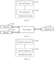
- An embodiment of the present disclosure provides a centralized unit entity. As shown in FIG. 12 , the centralized unit entity includes:
- the centralized unit entity further includes:
- the centralized unit entity further includes: a first receiving unit 1201, configured to receive a response message sent in parallel by each first DU.
- the centralized unit entity further includes: a first receiving unit 1201, configured to receive an RRC reconfiguration completion message sent in parallel by each first DU.
- the centralized unit entity further includes:
- the foregoing centralized unit entity provided by the present disclosure can implement all method steps implemented by the foregoing embodiments of the interaction method, the same technical effects can be achieved, and details about the same parts and beneficial effects as the method embodiments are not described in this embodiment again.
- the distributed unit entity may include a transceiver 1301, a processor 1302, and a memory 1303.
- the transceiver 1301 is configured to receive and send data under a control of the processor 1302.
- the bus architecture may include any quantity of interconnecting buses and bridges, specifically link together various circuits including one or more memories represented by the processor(s) 1302 and a memory represented by the memory 1303.
- the bus architecture may also link various other circuits together such as peripherals, voltage regulators, power management circuits or the like, which are well known in the art and, therefore, are not further described herein.
- a bus interface provides an interface.
- the transceiver 1301 may be a plurality of components, including a transmitter and a receiver, providing a unit for communicating with various other apparatuses over a transmission medium.
- the transmission medium includes transmission media such as wireless channels, wired channels, optical cables, etc.
- the processor 1302 is responsible for managing the bus architecture and general processing, and the memory 1303 can store data used by the processor 1302 when performing an operation.
- the processor 1302 may be a central processing unit (Central Processing Unit, CPU), an application specific integrated circuit (Application Specific Integrated Circuit, ASIC), a field-programmable gate array (Field-Programmable Gate Array, FPGA), or a complex programmable logic device (Complex Programmable Logic Device, CPLD).
- the processor may also use a multi-core architecture.
- the processor 1302 is configured to execute any method for positioning a reference device provided by the embodiments of the present disclosure according to the obtained executable instructions by invoking a computer program stored in the memory 1303.
- the processor and memory may also be physically separated.
- the processor 1302 when executing the computer program stored in the memory 1303, the processor 1302 implements the following operations:
- the foregoing distributed unit entity provided by the present disclosure can implement all method steps implemented by the foregoing embodiments of the interaction method, the same technical effects can be achieved, and details about the same parts and beneficial effects as the method embodiments are not described in this embodiment again.
- An embodiment of the present disclosure provides a distributed unit entity. As shown in FIG. 14 , the distributed unit entity includes:
- the distributed unit entity provided by the present disclosure can implement all method steps implemented by the foregoing embodiments of the interaction method, the same technical effects can be achieved, and details about the same parts and beneficial effects as the method embodiments are not described in this embodiment again.
- the user equipment may include a transceiver 1501, a processor 1502, and a memory 1503.
- the transceiver 1501 is configured to receive and send data under a control of the processor 1502.
- the bus architecture may include any quantity of interconnected buses and bridges, specifically link together various circuits including one or more memories represented by the processor(s) 1502 and a memory represented by the memory 1503.
- the bus architecture may also link various other circuits together such as peripherals, voltage regulators, power management circuits or the like, which are well known in the art and, therefore, are not further described herein.
- a bus interface provides an interface.
- the Transceiver 1501 may be a plurality of components, including a transmitter and a receiver, providing a unit for communicating with various other apparatuses over a transmission medium.
- the transmission medium includes transmission media such as wireless channels, wired channels, optical cables, etc.
- the processor 1502 is responsible for managing the bus architecture and general processing, and the memory 1503 can store data used by the processor 1502 when executing an operation.
- the processor 1502 may be a central processing unit (Central Processing Unit, CPU), an application specific integrated circuit (Application Specific Integrated Circuit, ASIC), a field-programmable gate array (Field-Programmable Gate Array, FPGA), or a complex programmable logic device (Complex Programmable Logic Device, CPLD).
- the processor may also use a multi-core architecture.
- the processor 1502 is configured to execute, according to the obtained executable instructions, any method associated with the user equipment provided by the embodiments of the present disclosure by invoking a computer program stored in the memory 1503.
- the processor and memory may also be physically separated.
- the processor 1502 when executing the computer program stored in the memory 1503, the processor 1502 implements the following operations: sending an indication message to a plurality of distributed unit entities DUs accessed by a user equipment, where the indication message is used to instruct the plurality of DUs to send information to a centralized unit entity CU in parallel.
- the user equipment provided by the present disclosure can implement all method steps implemented by the foregoing embodiments of the interaction method, the same technical effects can be achieved, and details about the same parts and beneficial effects as the method embodiments are not described in this embodiment again.
- the user equipment includes: a third sending unit 1601, configured to send an indication message to a plurality of distributed unit entities DUs accessed by a user equipment, where the indication message is used to instruct the plurality of DUs to send information to a centralized unit entity CU in parallel.
- a third sending unit 1601 configured to send an indication message to a plurality of distributed unit entities DUs accessed by a user equipment, where the indication message is used to instruct the plurality of DUs to send information to a centralized unit entity CU in parallel.
- the user equipment provided by the present disclosure can implement all method steps implemented by the foregoing embodiments of the interaction method, the same technical effects can be achieved, and details about the same parts and beneficial effects as the method embodiments are not described in this embodiment again.
- the division of the units in the embodiments of the present disclosure is exemplary, and is merely a logical function division, and there may be other division manners in practical implementation.
- respective functional units in the embodiments of the present disclosure may be integrated into one processing unit, or each unit may exist alone physically, or two or more units are integrated into one unit.
- the integrated unit may be implemented in a form of hardware, and may also be implemented in a form of a software functional unit.
- the integrated unit When being implemented in the form of a software functional unit and sold or used as an independent product, the integrated unit may be stored in a processor-readable storage medium.
- the computer software product is stored in a storage medium and includes several instructions for instructing a computer device (which may be a personal computer, a server, or a network device, etc.) or a processor to execute all or a part of the steps of the methods in the embodiments of the present disclosure.
- the processor-readable storage medium may be any available medium or data storage device that can be accessed by the processor, including but not limited to a magnetic memory (such as a floppy disk, a hard disk, a magnetic tape, a magnetooptical disk (MO), etc.), an optical memory (such as a CD, a DVD, a BD, an HVD, etc.), and a semiconductor memory (such as a ROM, an EPROM, an EEPROM, a nonvolatile memory (NAND FLASH), a solid state disk (SSD)), etc.
- a magnetic memory such as a floppy disk, a hard disk, a magnetic tape, a magnetooptical disk (MO), etc.
- an optical memory such as a CD, a DVD, a BD, an HVD, etc.
- a semiconductor memory such as a ROM, an EPROM, an EEPROM, a nonvolatile memory (NAND FLASH), a solid state disk (SSD)
- processor-executable instructions may also be stored in a processor-readable memory that can guide a computer or other programmable data processing device to function in a particular manner, causing the instructions stored in the processor-readable memory to produce an article of manufacture including an instruction apparatus.
- the instruction apparatus implements functions specified in one or more processes in the flowcharts and/or one or more blocks in the block diagrams.
Landscapes
- Engineering & Computer Science (AREA)
- Computer Networks & Wireless Communication (AREA)
- Signal Processing (AREA)
- Mobile Radio Communication Systems (AREA)
Applications Claiming Priority (2)
| Application Number | Priority Date | Filing Date | Title |
|---|---|---|---|
| CN202210530972.6A CN117202402A (zh) | 2022-05-16 | 2022-05-16 | 交互方法和相关设备 |
| PCT/CN2023/093309 WO2023221838A1 (zh) | 2022-05-16 | 2023-05-10 | 交互方法和相关设备 |
Publications (2)
| Publication Number | Publication Date |
|---|---|
| EP4529341A1 true EP4529341A1 (de) | 2025-03-26 |
| EP4529341A4 EP4529341A4 (de) | 2025-09-10 |
Family
ID=88834560
Family Applications (1)
| Application Number | Title | Priority Date | Filing Date |
|---|---|---|---|
| EP23806790.4A Pending EP4529341A4 (de) | 2022-05-16 | 2023-05-10 | Interaktionsverfahren und zugehörige vorrichtung |
Country Status (4)
| Country | Link |
|---|---|
| US (1) | US20250280340A1 (de) |
| EP (1) | EP4529341A4 (de) |
| CN (1) | CN117202402A (de) |
| WO (1) | WO2023221838A1 (de) |
Family Cites Families (7)
| Publication number | Priority date | Publication date | Assignee | Title |
|---|---|---|---|---|
| CN108574967B (zh) * | 2017-03-13 | 2021-08-03 | 中兴通讯股份有限公司 | 一种数据传输方法及装置 |
| US10499376B2 (en) * | 2017-06-16 | 2019-12-03 | Kt Corporation | Methods for managing resource based on open interface and apparatuses thereof |
| CN109429183B (zh) * | 2017-08-25 | 2021-08-24 | 中兴通讯股份有限公司 | 一种用户面模式的选择、调整方法、装置和设备 |
| CN110366202B (zh) * | 2018-03-26 | 2022-07-26 | 中兴通讯股份有限公司 | 空口链路拥塞反馈方法、装置及设备、存储介质 |
| CN110753372B (zh) * | 2018-07-24 | 2023-05-30 | 中兴通讯股份有限公司 | 基带处理分离架构中的信息处理方法、装置及存储介质 |
| CN114071613B (zh) * | 2020-08-07 | 2025-03-11 | 华为技术有限公司 | 一种iab节点的配置方法及通信装置 |
| CN112752230B (zh) * | 2020-12-28 | 2022-03-25 | 京信网络系统股份有限公司 | 消息识别方法、系统、集中单元、分布单元和存储介质 |
-
2022
- 2022-05-16 CN CN202210530972.6A patent/CN117202402A/zh active Pending
-
2023
- 2023-05-10 EP EP23806790.4A patent/EP4529341A4/de active Pending
- 2023-05-10 WO PCT/CN2023/093309 patent/WO2023221838A1/zh not_active Ceased
- 2023-05-10 US US18/859,160 patent/US20250280340A1/en active Pending
Also Published As
| Publication number | Publication date |
|---|---|
| US20250280340A1 (en) | 2025-09-04 |
| CN117202402A (zh) | 2023-12-08 |
| WO2023221838A1 (zh) | 2023-11-23 |
| EP4529341A4 (de) | 2025-09-10 |
Similar Documents
| Publication | Publication Date | Title |
|---|---|---|
| US11184886B2 (en) | Method, base station, and user equipment for implementing carrier aggregation | |
| EP4236424A1 (de) | Datenübertragungssteuerungsverfahren, vorrichtung und speichermedium | |
| CN114071612B (zh) | 辅小区组的主小区更新方法、装置及存储介质 | |
| EP4195718A1 (de) | Verfahren zur kommunikation zwischen einem benutzerendgerät und einem netzwerk sowie endgerät, netzwerkvorrichtung und vorrichtung | |
| EP4366375A1 (de) | Gruppenübergabeverfahren, -vorrichtung und -vorrichtung sowie speichermedium | |
| CN114828158B (zh) | 信息传输方法、装置、基站及介质 | |
| US20250008380A1 (en) | Qos parameter configuration method, device and apparatus, and storage medium | |
| WO2022152092A1 (zh) | 数据传输控制方法和装置 | |
| WO2023273824A1 (zh) | 切换方法、装置、网络设备及中继终端 | |
| CN115707151A (zh) | 状态转换方法、装置、设备以及存储介质 | |
| EP4529341A1 (de) | Interaktionsverfahren und zugehörige vorrichtung | |
| CN114585110B (zh) | 终端进入非激活态的控制方法和装置 | |
| CN114599120B (zh) | 终端rrc连接恢复的方法和装置 | |
| WO2024027450A1 (zh) | 保持辅节点不变的方法及装置 | |
| EP4258803A1 (de) | Verfahren und vorrichtung zur rrc-verbindungswiederherstellung eines endgeräts | |
| CN115134949A (zh) | 信息发送方法、装置、设备以及存储介质 | |
| CN116939655A (zh) | 业务数据传输方法、终端、网络节点和存储介质 | |
| CN115734384A (zh) | 连接建立的方法、设备及可读存储介质 | |
| EP4598094A1 (de) | Verfahren und vorrichtung zum eintritt in einen verbundenen zustand sowie endgerät und netzwerkvorrichtung | |
| EP4597895A1 (de) | Signalisierungsübertragungsverfahren und -vorrichtung auf steuerebene und speichermedium | |
| WO2023241181A1 (zh) | 指示方法、终端及网络侧设备 | |
| CN117998483A (zh) | 候选小区的切换方法和装置 | |
| CN115707045A (zh) | 无线资源控制rrc重建的处理方法、装置及终端 | |
| KR20240036103A (ko) | 세컨더리 셀 그룹의 버퍼 데이터 상태 정보의 전송 방법 및 장치 | |
| CN117528762A (zh) | 定位消息传输方法、设备、装置及存储介质 |
Legal Events
| Date | Code | Title | Description |
|---|---|---|---|
| STAA | Information on the status of an ep patent application or granted ep patent |
Free format text: STATUS: THE INTERNATIONAL PUBLICATION HAS BEEN MADE |
|
| PUAI | Public reference made under article 153(3) epc to a published international application that has entered the european phase |
Free format text: ORIGINAL CODE: 0009012 |
|
| STAA | Information on the status of an ep patent application or granted ep patent |
Free format text: STATUS: REQUEST FOR EXAMINATION WAS MADE |
|
| 17P | Request for examination filed |
Effective date: 20241022 |
|
| AK | Designated contracting states |
Kind code of ref document: A1 Designated state(s): AL AT BE BG CH CY CZ DE DK EE ES FI FR GB GR HR HU IE IS IT LI LT LU LV MC ME MK MT NL NO PL PT RO RS SE SI SK SM TR |
|
| REG | Reference to a national code |
Ref country code: DE Ref legal event code: R079 Free format text: PREVIOUS MAIN CLASS: H04W0076100000 Ipc: H04W0076190000 |
|
| DAV | Request for validation of the european patent (deleted) | ||
| DAX | Request for extension of the european patent (deleted) | ||
| A4 | Supplementary search report drawn up and despatched |
Effective date: 20250808 |
|
| RIC1 | Information provided on ipc code assigned before grant |
Ipc: H04W 76/19 20180101AFI20250804BHEP Ipc: H04W 76/10 20180101ALI20250804BHEP Ipc: H04W 76/27 20180101ALI20250804BHEP Ipc: H04W 88/08 20090101ALN20250804BHEP |