EP4529343A1 - Verfahren und vorrichtung zur optimierung der mobilitätsrobustheit für sprachfallback in einem mobilkommunikationssystem der nächsten generation - Google Patents
Verfahren und vorrichtung zur optimierung der mobilitätsrobustheit für sprachfallback in einem mobilkommunikationssystem der nächsten generation Download PDFInfo
- Publication number
- EP4529343A1 EP4529343A1 EP24803765.7A EP24803765A EP4529343A1 EP 4529343 A1 EP4529343 A1 EP 4529343A1 EP 24803765 A EP24803765 A EP 24803765A EP 4529343 A1 EP4529343 A1 EP 4529343A1
- Authority
- EP
- European Patent Office
- Prior art keywords
- varrlf
- report
- lte cell
- cell
- rrc connection
- Prior art date
- Legal status (The legal status is an assumption and is not a legal conclusion. Google has not performed a legal analysis and makes no representation as to the accuracy of the status listed.)
- Pending
Links
Images




Classifications
-
- H—ELECTRICITY
- H04—ELECTRIC COMMUNICATION TECHNIQUE
- H04W—WIRELESS COMMUNICATION NETWORKS
- H04W76/00—Connection management
- H04W76/10—Connection setup
- H04W76/18—Management of setup rejection or failure
-
- H—ELECTRICITY
- H04—ELECTRIC COMMUNICATION TECHNIQUE
- H04J—MULTIPLEX COMMUNICATION
- H04J11/00—Orthogonal multiplex systems, e.g. using WALSH codes
- H04J11/0069—Cell search, i.e. determining cell identity [cell-ID]
-
- H—ELECTRICITY
- H04—ELECTRIC COMMUNICATION TECHNIQUE
- H04W—WIRELESS COMMUNICATION NETWORKS
- H04W36/00—Hand-off or reselection arrangements
-
- H—ELECTRICITY
- H04—ELECTRIC COMMUNICATION TECHNIQUE
- H04W—WIRELESS COMMUNICATION NETWORKS
- H04W36/00—Hand-off or reselection arrangements
- H04W36/0005—Control or signalling for completing the hand-off
- H04W36/0055—Transmission or use of information for re-establishing the radio link
- H04W36/0079—Transmission or use of information for re-establishing the radio link in case of hand-off failure or rejection
-
- H—ELECTRICITY
- H04—ELECTRIC COMMUNICATION TECHNIQUE
- H04W—WIRELESS COMMUNICATION NETWORKS
- H04W36/00—Hand-off or reselection arrangements
- H04W36/14—Reselecting a network or an air interface
- H04W36/144—Reselecting a network or an air interface over a different radio air interface technology
-
- H—ELECTRICITY
- H04—ELECTRIC COMMUNICATION TECHNIQUE
- H04W—WIRELESS COMMUNICATION NETWORKS
- H04W76/00—Connection management
- H04W76/10—Connection setup
- H04W76/19—Connection re-establishment
-
- H—ELECTRICITY
- H04—ELECTRIC COMMUNICATION TECHNIQUE
- H04W—WIRELESS COMMUNICATION NETWORKS
- H04W76/00—Connection management
- H04W76/20—Manipulation of established connections
- H04W76/27—Transitions between radio resource control [RRC] states
Definitions
- the disclosure relates to a method and device for optimizing mobility robustness for a voice fallback in a next generation mobile communication system and, particularly, to an operation and device for including the ID of a cell to which a terminal reconnects and information associated with a time that elapsed from an RLF, when making an RLF report.
- 5G mobile communication technologies define broad frequency bands such that high transmission rates and new services are possible, and can be implemented not only in “Sub 6GHz” bands such as 3.5GHz, but also in “Above 6GHz” bands referred to as mmWave including 28GHz and 39GHz.
- 6G mobile communication technologies referred to as Beyond 5G systems
- terahertz bands for example, 95GHz to 3THz bands
- IIoT Industrial Internet of Things
- IAB Integrated Access and Backhaul
- DAPS Dual Active Protocol Stack
- 5G baseline architecture for example, service based architecture or service based interface
- NFV Network Functions Virtualization
- SDN Software-Defined Networking
- MEC Mobile Edge Computing
- multi-antenna transmission technologies such as Full Dimensional MIMO (FD-MIMO), array antennas and large-scale antennas, metamaterial-based lenses and antennas for improving coverage of terahertz band signals, high-dimensional space multiplexing technology using OAM (Orbital Angular Momentum), and RIS (Reconfigurable Intelligent Surface), but also full-duplex technology for increasing frequency efficiency of 6G mobile communication technologies and improving system networks, AI-based communication technology for implementing system optimization by utilizing satellites and AI (Artificial Intelligence) from the design stage and internalizing end-to-end AI support functions, and next-generation distributed computing technology for implementing services at levels of complexity exceeding the limit of UE operation capability by utilizing ultra-high-performance communication and computing resources.
- FD-MIMO Full Dimensional MIMO
- OAM Organic Angular Momentum
- RIS Reconfigurable Intelligent Surface
- An operation method of a terminal in a wireless communication system may include an operation of receiving, from an NR base station, a handover-from-NR command message including information in which a target radio access technology (RAT) is configured to LTE, an operation of selecting a suitable LTE cell when an available suitable LTE cell exists and selecting an acceptable LTE cell when an available suitable LTE cell does not exist in the case in which a failure of a handover from NR is detected, an operation of entering an RRC idle mode, an operation of performing an RRC connection establishment procedure with respect to the selected LTE cell, an operation of storing a time value from the handover failure to reconnection and an ID of the LTE cell to which the RRC connection is performed in VarRLF-Report associated with the NR when the LTE cell to which the RRC connection is performed is a suitable LTE cell, and an operation of storing a time value from the handover failure to reconnection in the VarRLF-Report associated with the NR when the LTE cell to which the RRC connection is performed is a
- the ID of the LTE cell to which the RRC connection is performed may not be stored in the VarRLF-Report associated with the NR.
- the handover-from-NR command message may include an indicator for a voice fallback.
- the method of the terminal may further include an operation of storing, in the VarRLF-Report associated with the NR, information indicating that the handover is for a voice fallback.
- the operation of storing the time value from the handover failure to the reconnection or the ID of the LTE cell to which the RRC connection is performed in the VarRLF-Report associated with the NR may be performed when an ID of an LTE cell is not stored in the VarRLF-Report associated with the NR.
- the terminal may be a terminal that supports an inter-RAT RLF report.
- the method of the terminal may further include an operation of establishing an RRC connection with the NR base station after updating the VarRLF-Report associated with the NR in relation to the selected LTE cell, an operation of receiving a terminal information request message from the NR base station, and an operation of transmitting, to the NR base station, a terminal information response message including the VarRLF-Report associated with the NR.
- a terminal in a wireless communication system may include a transceiver and a controller, and the controller may be configured to receive, from an NR base station, a handover-from-NR command message including information in which a target radio access technology (RAT) is configured to LTE, to select a suitable LTE cell when an available suitable LTE cell exists and select an acceptable LTE cell when an available suitable LTE cell does not exist in the case in which a failure of a handover from NR is detected, to enter an RRC idle mode, to perform an RRC connection establishment procedure with respect to the selected LTE cell, to store a time value from the handover failure to reconnection and an ID of the LTE cell to which the RRC connection is performed in VarRLF-Report associated with the NR when the LTE cell to which the RRC connection is performed is a suitable LTE cell, and to store a time value from the handover failure to reconnection in the VarRLF-Report associated with the NR when the LTE cell to which the RRC connection is performed is a suitable L
- a terminal in relation to a voice fallback, includes the ID of a cell to which the terminal reconnects and information associated with a time that elapsed from an RLF when making an RLF report, so that an operator that manages base stations may effectively operate a network based on the information.
- eNB 3rd generation partnership project long term evolution
- gNB 3rd generation partnership project long term evolution
- FIG. 1 illustrates a structure of an LTE system according to an embodiment of the disclosure.
- a radio access network of an LTE system includes next-generation base stations (evolved node Bs, hereinafter ENBs, node Bs, or base stations) 1-05, 1-10, 1-15, and 1-20, a mobility management entity (MME) 1-25, and a serving gateway (S-GW) 1-30.
- ENBs evolved node Bs
- MME mobility management entity
- S-GW serving gateway
- a user equipment (hereinafter UE or terminal) 1-35 accesses an external network through the ENBs 1-05 to 1-20 and the S-GW 1-30.
- the ENBs 1-05 to 1-20 each correspond to a conventional node B in a UMTS system.
- the ENBs are connected to the UE 1-35 through a radio channel, and perform more complicated roles than the conventional node Bs.
- VoIP voice over IP
- a device that collects state information, such as buffer states, available transmit power states, and channel states of UEs, and performs scheduling accordingly is required, and the ENBs 1-05 to 1-20 serve as the device.
- one ENB controls multiple cells.
- the LTE system uses orthogonal frequency division multiplexing (hereinafter referred to as OFDM) as a radio access technology in a bandwidth of, for example, 20 MHz.
- OFDM orthogonal frequency division multiplexing
- the next-generation mobile communication system employs an adaptive modulation & coding (hereinafter referred to as AMC) scheme for determining a modulation scheme and a channel coding rate according to a channel state of a UE.
- AMC adaptive modulation & coding
- the S-GW 1-30 is a device that provides a data bearer, and generates or removes a data bearer under the control of the MME 1-25.
- the MME is a device responsible for various control functions as well as a mobility management function for a UE, and is connected to multiple base stations.
- FIG. 2 illustrates a radio protocol structure of an LTE system according to an embodiment of the disclosure.
- a radio protocol of an LTE system includes a packet data convergence protocol (PDCP) 2-05 or 2-40, a radio link control (RLC) 2-10 or 2-35, and a medium access control (MAC) 2-15 or 2-30 on each of UE and ENB sides.
- the packet data convergence protocol (PDCP) 2-05 or 2-40 is responsible for operations such as IP header compression/reconstruction.
- the main functions of the PDCP are summarized as follows.
- the radio link control (hereinafter referred to as RLC) 2-10 or 2-35 reconfigures a PDCP protocol data unit (PDU) into an appropriate size to perform an ARQ operation. etc.
- RLC radio link control
- the MAC 2-15 or 2-30 is connected to several RLC layer devices configured in a single terminal, and multiplexes RLC PDUs into a MAC PDU and demultiplexes a MAC PDU into RLC PDUs.
- the main functions of the MAC are summarized as follows.
- a physical layer 2-20 or 2-25 performs operations of channel-coding and modulating upper layer data, thereby obtaining OFDM symbols, and delivering the same through a radio channel, or demodulating OFDM symbols received through the radio channel, channel-decoding the same, and delivering the same to the upper layer.
- FIG. 3 illustrates a structure of a next-generation mobile communication system according to an embodiment of the disclosure.
- a radio access network of a next-generation mobile communication system includes a next-generation base station (new radio node B, hereinafter NR gNB or NR base station) 3-10, and a new radio core network (NR CN) 3-05.
- a user terminal new radio user equipment, hereinafter NR UE or NR terminal
- NR UE new radio user equipment
- the NR gNB 3-10 may be connected to the NR UE 3-15 through a radio channel and provide outstanding services as compared to a conventional node B.
- a device that collects state information, such as buffer statuses, available transmit power states, and channel states of UEs, and performs scheduling accordingly is required, and the NR gNB 3-10 serves as the device.
- state information such as buffer statuses, available transmit power states, and channel states of UEs, and performs scheduling accordingly is required, and the NR gNB 3-10 serves as the device.
- one NR gNB controls multiple cells.
- the next-generation mobile communication system may have a wider bandwidth than the existing maximum bandwidth, may employ an orthogonal frequency division multiplexing (hereinafter referred to as OFDM) as a radio access technology, and may additionally integrate a beamforming technology therewith. Furthermore, the next-generation mobile communication system employs an adaptive modulation & coding (hereinafter referred to as AMC) scheme for determining a modulation scheme and a channel coding rate according to a channel state of a UE.
- AMC adaptive modulation & coding
- the NR CN 3-05 performs functions such as mobility support, bearer configuration, and QoS configuration.
- the NR CN 3-05 is a device responsible for various control functions as well as a mobility management function for a UE, and may be connected to multiple base stations.
- the next-generation mobile communication system may interwork with the existing LTE system, and the NR CN is connected to an MME 3-25 via a network interface.
- the MME is connected to an eNB 3-30 that is an existing base station.
- FIG. 4 illustrates a radio protocol structure of a next-generation mobile communication system according to an embodiment of the disclosure.
- FIG. 4 illustrates a radio protocol structure of a next-generation mobile communication system to which the disclosure is applicable.
- a radio protocol of a next-generation mobile communication system includes an NR SDAP 4-01 or 4-45, an NR PDCP 4-05 or 4-40, an NR RLC 4-10 or 4-35, and an NR MAC 4-15 or 4-30 on each of UE and NR base station sides.
- the main functions of the NR SDAP 4-01 or 4-45 may include some of functions below.
- the UE may be configured, through an RRC message, whether to use the header of the SDAP layer device or whether to use functions of the SDAP layer device for each PDCP layer device or each bearer or each logical channel, and if an SDAP header is configured, the non-access stratum (NAS) QoS reflection configuration 1-bit indicator (NAS reflective QoS) and the AS QoS reflection configuration 1-bit indicator (AS reflective QoS) of the SDAP header may be indicated so that the UE can update or reconfigure mapping information regarding the QoS flow and data bearer of the uplink and downlink.
- the SDAP header may include QoS flow ID information indicating the QoS.
- the QoS information may be used as data processing priority, scheduling information, etc. for smoothly supporting services.
- the main functions of the NR PDCP 4-05 or 4-40 may include some of functions below.
- the reordering of the NR PDCP device refers to a function of reordering PDCP PDU received from a lower layer in an order based on PDCP sequence numbers (SNs), and may include a function of transferring data to an upper layer according to a rearranged order, may include a function of directly transferring data without considering order, may include a function of rearranging order to record lost PDCP PDUs, may include a function of reporting the state of lost PDCP PDUs to a transmission side, or may include a function of requesting retransmission of lost PDCP PDUs.
- SNs PDCP sequence numbers
- the main functions of the NR RLC 4-10 or 4-35 may include some of functions below.
- the in-sequence delivery of the NR RLC device refers to a function of successively delivering RLC SDUs received from the lower layer to the upper layer, may include a function of reassembling and delivering multiple RLC SDUs received, into which one original RLC SDU has been segmented, may include a function of reordering the received RLC PDUs with reference to the RLC sequence number (SN) or PDCP sequence number (SN), may include a function of recording RLC PDUs lost as a result of reordering, may include a function of reporting the state of the lost RLC PDUs to the transmitting side, and may include a function of requesting retransmission of the lost RLC PDUs, may include a function of, if there is a lost RLC SDU, successively delivering only RLC SDUs before the lost RLC SDU to the upper layer, may include a function of, if a predetermined timer has expired although there is a lost RLC SDU, successively delivering all
- the NR RLC device may process RLC PDUs in the received order (regardless of the sequence number order, in the order of arrival) and deliver same to the PDCP device regardless of the order (out-of-sequence delivery), and may, in the case of segments, receiving segments which are stored in a buffer or which are to be received later, reconfigure same into one complete RLC PDU, process, and deliver same to the PDCP device.
- the NR RLC layer may include no concatenation function, which may be performed in the NR MAC layer or replaced with a multiplexing function of the NR MAC layer.
- the out-of-sequence delivery of the NR RLC device refers to a function of instantly delivering RLC SDUs received from the lower layer to the upper layer regardless of the order, may include a function of, if multiple RLC SDUs received, into which one original RLC SDU has been segmented, are received, reassembling and delivering the same, and may include a function of storing the RLC SN or PDCP SN of received RLC PDUs, and recording RLC PDUs lost as a result of reordering.
- the NR MAC 14-15 or 4-30 may be connected to multiple NR RLC layer devices configured in one UE, and the main functions of the NR MAC may include some of functions below.
- An NR PHY layer 4-20 or 4-25 may perform operations of channel-coding and modulating upper layer data, thereby obtaining OFDM symbols, and delivering the same through a radio channel, or demodulating OFDM symbols received through the radio channel, channel-decoding the same, and delivering the same to the upper layer.
- FIG. 5 is a flowchart of a process of updating radio link failure information or handover failure information in an RRC connection establishment procedure, after an RRC connection re-establishment procedure performed by a UE fails in a next generation mobile communication system according to an embodiment of the disclosure.
- a UE 5-01 may be in an RRC connected mode (RRC_CONNECTED) by configuring an RRC connection with an NR base station 5-02 in operation 5-05.
- RRC_CONNECTED RRC connected mode
- the UE 5-01 may transmit a UE capability information message (UECapabilityInformation) to the base station 5-02.
- UECapabilityInformation UECapabilityInformation
- An indicator associated with an acceptable cell may be included in the message, and this may be an indicator associated with cells different from a suitable cell of VarRLF-Report.
- the message may include UE capability information associated with capability of storing information different from a suitable cell of VarRLF-Report.
- the UE 5-01 may detect a radio link failure (RLF) or a handover failure may occur (handover failure or reconfiguration with sync failure) due to a predetermined reason.
- RLF radio link failure
- the UE may detect an RLF when a timer T310 expires for a currently connected primary cell (PCell) 5-02 or a handover failure may occur when a timer T304 expires although the UE receives an RRC message (e.g., RRCReconfiguration or MobilityFromNRCommand) indicating handover is required from the currently connected primary cell.
- RRC message e.g., RRCReconfiguration or MobilityFromNRCommand
- the UE 5-01 may store radio link failure information (when detecting an RLF) or handover failure information (when a handover failure occurs) in VarRLF-Report. Specifically, the UE may store the radio link failure information or the handover failure information in the VarRLF-Report according to the following procedure.
- the UE shall determine the content in the VarRLF-Report as follows:
- the UE may determine rlf-Cause according to the following procedure.
- the UE shall set the rlf-Cause in the VarRLF-Report as follows:
- the UE 5-01 may initiate an RRC connection re-establishment procedure. However, the UE 5-01 may not successfully perform the procedure but fails due to a predetermined reason. For example, the UE may operate a timer T311 when the RRC connection re-establishment procedure is initiated, but when the UE fails to select a suitable NR cell before the timer T311 expires, the procedure may fail.
- the UE 5-01 may transition to an RRC idle (RRC_IDLE) mode.
- RRC_IDLE RRC idle
- the UE 5-01 may camp on an acceptable NR cell 5-03.
- the UE 5-01 may perform an RRC connection establishment procedure in order to establish an RRC connection with the acceptable NR cell 5-03. That is, the UE 5-01 may transmit an RRC connection establishment request message (RRCSetupRequest) to the cell 5-03. In response thereto, the cell may transmit an RRC connection establishment message (RRCSetup) to the UE in operation 5-45. In operation 5-46, the UE may transition to an RRC connected mode (RRC_CONNECTED) by applying RRCSetup. The UE may consider or determine the cell as a current PCell. In operation 5-48, the UE according to the disclosure may propose performing at least one of the proposed methods (i.e., one of the following methods or a combination of some or all of the methods) according to the following conditions.
- RRCSetupRequest RRC connection establishment request message
- RRCSetup RRC connection establishment message
- RRC_CONNECTED RRC connected mode
- the UE may consider or determine the cell as a current PCell.
- the UE according to the disclosure may
- a base station may control which method the UE is to apply according to a configuration.
- the UE may transmit an RRC connection establishment complete (RRCSetupComplete) message to the cell in operation 5-50.
- the UE may transmit the VarRLF-Report to the suitable cell 5-02 later via a UE information procedure, and an operator that manages a suitable cell may optimize a network based on the corresponding information. For example, based on the timeUntilReconnection information, the operator may identify how much time elapsed from an RRC connection re-establishment failure until the UE having radio link failure information or handover failure information in VarRLF-Report configures an RRC connection again with a predetermined cell.
- the operator may operate a network by additionally providing a new cell or optimizing existing cells.
- the operator may identify a cell to which the UE has subsequently connected, and this information may be used for determining whether to additionally provide a cell or to appropriately manage existing cells.
- the reconnectCellId for an acceptable cell is set in VarRLF-Report, the UE may not report the corresponding information to a suitable cell.
- An acceptable cell does not belong to an operator which the UE subscribes to, and thus, if the UE sends reconnectCellId to a subscribed operator, it is provision of network operation information of another operator.
- FIG. 6 is a flowchart of a process of updating radio link failure information or handover failure information in an RRC connection establishment procedure, after an RRC connection re-establishment procedure performed by a UE fails in a next generation mobile communication system according to an embodiment of the disclosure.
- a UE 6-01 may be in an RRC connected mode (RRC_CONNECTED) by configuring an RRC connection with an NR base station 6-02 in operation 6-05.
- RRC_CONNECTED RRC connected mode
- the UE 6-01 may transmit a UE capability information message (UECapabilityInformation) to the base station 6-02. This may be the same as the above-described embodiment.
- UECapabilityInformation UE capability information message
- the UE 6-01 may detect a radio link failure (RLF) or a handover failure may occur (handover failure or reconfiguration with sync failure) due to a predetermined reason.
- RLF radio link failure
- the UE may detect an RLF when a timer T310 expires for a currently connected primary cell (PCell) 6-02 or a handover failure may occur when a timer T304 expires although the UE receives an RRC message (e.g., RRCReconfiguration or MobilityFromNRCommand) indicating handover is required from the currently connected primary cell.
- RRC message e.g., RRCReconfiguration or MobilityFromNRCommand
- the UE 6-01 may store radio link failure information (when detecting an RLF) or handover failure information (when a handover failure occurs) in VarRLF-Report. This may be the same as the above-described embodiment.
- the UE 6-01 may initiate an RRC connection re-establishment procedure. However, the UE 6-01 may not successfully perform the procedure but fails due to a predetermined reason. For example, the UE may operate a timer T311 when the RRC connection re-establishment procedure is initiated, but when the UE fails to select a suitable NR cell before the timer T311 expires, the procedure may fail.
- the UE 6-01 may transition to an RRC idle mode (RRC_IDLE).
- RRC_IDLE RRC idle mode
- the UE 6-01 may camp on an acceptable LTE cell 6-03.
- the UE 6-01 may perform an RRC connection establishment procedure in order to establish an RRC connection with the acceptable cell 6-03. That is, the UE 6-01 may transmit an RRC connection establishment request message (RRCSetupRequest) to the cell 6-03. In response thereto, the cell may transmit an RRC connection establishment message (RRCSetup) to the UE in operation 6-45. In operation 6-46, the UE may transition to an RRC connected mode (RRC_CONNECTED) by applying RRCSetup. The UE may consider or determine the cell as a current PCell. In operation 6-48, the UE according to the disclosure may propose performing at least one of the proposed methods (i.e., one of the following methods or a combination of some or all of the methods) according to the following conditions.
- RRCSetupRequest RRC connection establishment request message
- RRCSetup RRC connection establishment message
- RRC_CONNECTED RRC connected mode
- the UE may consider or determine the cell as a current PCell.
- the UE according to the disclosure may propose performing
- a base station may control which method the UE is to apply according to a configuration.
- the UE may transmit an RRC connection establishment complete message (RRCConnectionSetupComplete) to the cell in operation 6-50.
- the UE may transmit the VarRLF-Report to the suitable cell 6-02 via a UE information procedure, and an operator that manages a suitable cell may optimize a network based on the corresponding information. For example, based on the timeUntilReconnection information, the operator may identify how much time elapsed from an RRC connection re-establishment failure until the UE having radio link failure information or handover failure information in VarRLF-Report configures an RRC connection again with a predetermined cell.
- the operator may operate a network by additionally providing a new cell or optimizing existing cells.
- the operator may identify a cell to which the UE has subsequently connected, and this information may be used for determining whether to additionally provide a cell or to appropriately manage existing cells.
- the reconnectCellId for an acceptable cell is set in VarRLF-Report, the UE may not report the corresponding information to a suitable cell.
- An acceptable cell does not belong to an operator which the UE subscribes to, and thus, if the UE sends reconnectCellId to a subscribed operator, it is provision of network operation information of another operator.
- FIG. 7 is a flowchart of a process of updating radio link failure information or handover failure information in an RRC connection establishment procedure, after an RRC connection re-establishment procedure performed by a UE fails in a next generation mobile communication system according to an embodiment of the disclosure.
- a UE 7-01 may be in an RRC connected mode (RRC_CONNECTED) by configuring an RRC connection with an LTE base station 7-02.
- the LTE base station may be connected to an EPC or 5GC in operation 7-05.
- the UE 7-01 may transmit a UE capability information message (UECapabilityInformation) to the base station 7-02.
- UECapabilityInformation UE capability information message
- An indicator associated with an acceptable cell may be included in the message, and this may be an indicator associated with cells different from a suitable cell of VarRLF-Report.
- the message may include UE capability information associated with capability of storing information different from a suitable cell of VarRLF-Report.
- the UE 7-01 may detect a radio link failure (RLF) or a handover failure may occur (handover failure) due to a predetermined reason.
- RLF radio link failure
- the UE may detect an RLF when a timer T310 expires for a currently connected primary cell (PCell) 7-02, or a handover failure may occur when a timer T304 expires although the UE receives an RRC message (e.g., RRCConnectionReconfiguration or MobilityFromEUTRACommand such that targetRAT-Type is set to nr) indicating handover is required from the currently connected primary cell.
- RRC message e.g., RRCConnectionReconfiguration or MobilityFromEUTRACommand such that targetRAT-Type is set to nr
- the UE 7-01 may store radio link failure information (when detecting an RLF) or handover failure information (when a handover failure occurs) in the VarRLF-Report. Specifically, the UE may store the radio link failure information in the VarRLF-Report according to the following procedure.
- the UE may store the handover failure information in the VarRLF-Report according to the following procedure.
- the UE 7-01 may initiate an RRC connection re-establishment procedure.
- the UE 7-01 may not successfully perform the procedure but fails due to a predetermined reason.
- the UE may operate a timer T311 when the RRC connection re-establishment procedure is initiated, but when the UE fails to select a suitable LTE cell before the timer T311 expires, the procedure may fail.
- the UE 7-01 may transition to an RRC idle mode (RRC_IDLE).
- RRC_IDLE RRC idle mode
- the UE 7-01 may camp on an acceptable LTE cell 7-03.
- the UE 7-01 may perform an RRC connection establishment procedure in order to establish an RRC connection with the acceptable LTE cell 7-03. That is, the UE 7-01 may transmit an RRC connection establishment request message (RRCConnectionRequest) to the cell 7-03. In response thereto, the cell may transmit an RRC connection establishment message (RRCConnectionSetup) to the UE in operation 7-45. In operation 7-46, the UE may transition to an RRC connected mode (RRC_CONNECTED) by applying RRCConnectionSetup. The UE may consider or determine the cell as a current PCell. In operation 7-48, the UE according to the disclosure may propose performing at least one of the proposed methods (i.e., one of the following methods or a combination of some or all of the methods) according to the following conditions.
- the proposed methods i.e., one of the following methods or a combination of some or all of the methods
- a UE 8-01 may be in an RRC connected mode (RRC_CONNECTED) by configuring an RRC connection with an LTE base station 8-02.
- the LTE base station may be connected to an EPC or 5GC in operation 8-05.
- the UE 8-01 may initiate an RRC connection re-establishment procedure. However, the UE 8-01 may not successfully perform the procedure but fails due to a predetermined reason. For example, the UE may operate a timer T311 when the RRC connection re-establishment procedure is initiated, but when the UE fails to select a suitable LTE cell before the timer T311 expires, the procedure may fail.
- the UE 8-01 may transition to an RRC idle mode (RRC_IDLE).
- RRC_IDLE RRC idle mode
- the UE 8-01 may camp on an acceptable NR cell 8-03.
- the UE 8-01 may perform an RRC connection establishment procedure in order to establish an RRC connection with the acceptable NR cell 8-03. That is, the UE 8-01 may transmit an RRC connection establishment request message (RRCSetupRequest) to the cell 8-03. In response thereto, the cell may transmit an RRC connection establishment message (RRCSetup) to the UE in operation 8-45. In operation 8-46, the UE may transition to an RRC connected mode (RRC_CONNECTED) by applying RRCSetup. The UE may consider or determine the cell as a current PCell. In operation 8-48, the UE according to the disclosure may propose performing at least one of the proposed methods (i.e., one of the following methods or a combination of some or all of the methods) according to the following conditions.
- RRCSetupRequest RRC connection establishment request message
- RRCSetup RRC connection establishment message
- RRC_CONNECTED RRC connected mode
- the UE may consider or determine the cell as a current PCell.
- a base station may control which method the UE is to apply according to a configuration.
- the UE may transmit an RRC connection establishment complete message (RRCSetupComplete) to the cell in operation 8-50.
- RRCSetupComplete RRC connection establishment complete message
- the UE may transmit the VarRLF-Report to the suitable cell 8-02 via a UE information procedure, and an operator that manages a suitable cell may optimize a network based on the corresponding information. For example, based on the timeUntilReconnection information, the operator may identify how much time elapsed from an RRC connection re-establishment failure until the UE having radio link failure information or handover failure information in the VarRLF-Report configures an RRC connection again with a predetermined cell.
- the operator may operate a network by additionally providing a new cell or optimizing existing cells.
- the operator may identify a cell to which the UE has subsequently connected, and this information may be used for determining whether to additionally provide a cell or to appropriately manage existing cells.
- the reconnectCellId for an acceptable cell is set in the VarRLF-Report, the UE may not report the corresponding information to a suitable cell.
- An acceptable cell does not belong to an operator which the UE subscribes to, and thus, if the UE sends reconnectCellId to a subscribed operator, it is provision of network operation information of another operator.
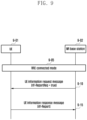
- FIG. 9 is a flowchart of a process in which a UE transfers radio link failure information or handover failure information to a base station in a next generation mobile communication system according to an embodiment of the disclosure.
- a UE 9-01 may be in an RRC connected mode (RRC_CONNECTED) by configuring an RRC connection with an NR base station 9-02 in operation 9-05.
- RRC_CONNECTED RRC connected mode
- the base station 9-02 may transmit a UE information request message (UEInformationRequest) to the UE 9-01 for which security is successfully activated.
- UEInformationRequest UE information request message
- rlf-ReportReq configured to true may be included.
- the UE 9-01 may perform the following procedure and may transmit a UE information response message (UEInformationResponse) to the base station 9-02.
- UEInformationResponse UE information response message
- FIG. 10 is a flowchart of a process in which a UE transfers radio link failure information or handover failure information to a base station in a next generation mobile communication system according to an embodiment of the disclosure.
- a UE 10-01 may be in an RRC connected mode (RRC_CONNECTED) by configuring an RRC connection with an LTE base station 10-02 in operation 10-05.
- RRC_CONNECTED RRC connected mode
- An LTE base station connected to an EPC may be referred to as an eNB
- an LTE base station connected to a 5GC may be referred to as an ng-eNB.
- the base station 10-02 may transmit a UE information request message (UEInformationRequest) to the UE 10-01 for which security is successfully activated.
- UEInformationRequest UE information request message
- rlf-ReportReq configured to true may be included.
- the UE 10-01 may perform the following procedure and may transmit a UE information response message (UEInformationResponse) to the base station 10-02.
- UEInformationResponse UE information response message
- RLF-Report included in the UE information response message may have an ASN.1 structure as shown below.
- the UE may configure RLF-Report by applying the above-described embodiment, and may include the same in the UE information response message.
- a UE 11-01 may be in an RRC connected mode (RRC_CONNECTED) by configuring an RRC connection with an NR base station 1-02.
- the UE 11-01 may receive a MobilityFromNRCommand message from the base station 11-02.
- targetRAT-Type configured to eutra may be included.
- voiceFallbackIndication may be included.
- the UE 11-01 may determine that a mobility from NR failure occurs due to a predetermined reason. For example, if connection to a target radio access technology is not successfully performed (if the UE does not succeed in establishing the connection to the target radio access technology), it is determined that a mobility from NR failure occurs.
- the UE 11-01 may store handover failure information in the VarRLF-Report. This may be performed according to at least one of the above-described embodiments.
- voiceFallbackIndication is included in MobilityFormNRCommand, or if the mobility from NR procedure is for an emergency services fallback, the UE may store an indicator indicating the same in the VarRLF-Report.
- the UE 11-01 may transition to an RRC idle mode (RRC_IDLE) when a suitable LTE cell 11-03 is selected.
- RRC_IDLE RRC idle mode
- the UE 11-01 may perform an RRC connection establishment procedure with the suitable LTE cell 11-03. That is, the UE may transmit an RRC connection establishment request message (RRCConnectionRequest) to the cell in operation 11-40. In response thereto, the cell may transmit an RRC connection configuration message (RRCConnectionSetup) to the UE in operation 11-45. The UE may transition to an RRC connected mode in operation 11-46, and may consider the cell a primary cell. When condition 1 is satisfied and accordingly condition 2 is satisfied, the UE may perform operation 1 in operation 11-50.
- RRCConnectionRequest RRC connection establishment request message
- RRCConnectionSetup RRC connection configuration message
- the UE 11-01 may transmit an RRC connection establishment complete message (RRCConnectionSetupComplete) to the cell 11-03.
- RRCConnectionSetupComplete RRC connection establishment complete message
- the UE may be in an RRC connected mode by configuring an RRC connection with the NR base station 11-02.
- the UE 11-01 may transmit a UE information response message (UEInformationResponse) including RLF-Report to the NR base station 11-02. This may be performed according to the above-described embodiment.
- UEInformationResponse UE information response message
- FIG. 12 is a flowchart of a process of updating radio link failure information or handover failure information in an RRC connection establishment procedure, after an RRC connection re-establishment procedure performed by a UE fails in a next generation mobile communication system according to an embodiment of the disclosure.
- a UE 12-01 may be in an RRC connected mode (RRC_CONNECTED) by configuring an RRC connection with an NR base station 12-02 in operation 12-05.
- RRC_CONNECTED RRC connected mode
- the UE 12-01 may transmit a UE capability information message (UECapabilityInformation) to the base station 12-02. This may be performed according to the above-described embodiment.
- UECapabilityInformation UE capability information message
- the UE 12-01 may receive a MobilityFromNRCommand message from the base station 12-02.
- targetRAT-Type may be configured to eutra.
- voiceFallbackIndication may be included.
- the UE 12-01 may determine that a mobility from NR failure occurs due to a predetermined reason. For example, if connection to a target radio access technology is not successfully performed (if the UE does not succeed in establishing the connection to the target radio access technology), it is determined that a mobility from NR failure occurs.
- the UE 12-01 may attempt to select an E-UTRA cell. For reference, if voiceFallbackIndication is included in MobilityFormNRCommand, or if the mobility from NR procedure is for an emergency services fallback, the UE may attempt to select an E-UTRA cell.
- the UE 12-01 may transition to an RRC idle mode (RRC_IDLE).
- the base station may recognize that the UE selects an acceptable E-UTRA cell that supports an emergency call in the case in which timeUntilReconnection and reconnectCellId do not exist and voiceFallbackIndication is included in MobilityFormNRCommand, or in the case in which an indicator indicating that a mobility from NR procedure is for an emergency services fallback is included in the RLF-Report.
- the UE may perform operation 1 in operation 12-50.
- whether to perform operation 1 or whether to not store any information in the VarRLF-Report may be determined based on a configuration by a base station.
- the UE 12-01 may transmit an RRC connection establishment complete message (RRCConnectionSetupComplete) to the cell 12-03.
- RRCConnectionSetupComplete RRC connection establishment complete message
- the UE may be in an RRC connected mode by configuring an RRC connection with the NR base station 12-02.
- the NR base station 12-02 may transmit a UE information request message (UEInformationRequest) to the UE 12-01 for which security is successfully activated.
- UEInformationRequest UE information request message
- rlf-ReportReq configured to true may be included.
- the UE 12-01 may transmit a UE information response message (UEInformationResponse) including RLF-Report to the NR base station 12-02. This may be performed according to the above-described embodiment.
- UEInformationResponse UE information response message
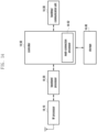
- FIG. 13 is a block diagram of the internal structure of a UE according to an embodiment of the disclosure.
- the UE includes a radio frequency (RF) processor 13-10, a baseband processor 13-20, a storage 13-30, and a controller 13-40.
- RF radio frequency
- the RF processor 13-10 performs a function for signal transmission or reception via a wireless channel, such as signal band conversion, amplification or the like. That is, the RF processor 13-10 up-converts a baseband signal provided from the baseband processor 13-20 into an RF band signal so as to transmit the RF band signal via an antenna, and down-converts an RF band signal received via the antenna into a baseband signal.
- the RF processor 13-10 may include a transmission filter, a reception filter, an amplifier, a mixer, an oscillator, a digital-to-analog converter (DAC), an analog-to-digital converter (ADC), and the like.
- the UE may include a plurality of antennas.
- the RF processor 13-10 may include a plurality of RF chains. Moreover, the RF processor 13-10 may perform beamforming. For the beamforming, the RF processor 13-10 may control the phase and the size of each of the signals transmitted or received via a plurality of antennas or antenna elements. In addition, the RF processor may perform MIMO, and may receive multiple layers when performing a MIMO operation.
- the baseband processor 13-20 executes a function of conversion between a baseband signal and a bitstream according to the physical layer standard of a system. For example, in the case of data transmission, the baseband processor 13-20 encodes and modulates a transmission bitstream, so as to produce complex symbols. In addition, in the case of data reception, the baseband processor 13-20 restores a reception bitstream by demodulating and decoding a baseband signal provided from the RF processor 13-10.
- the baseband processor 13-20 in the case of data transmission, produces complex symbols by encoding and modulating a transmission bitstream, maps the complex symbols to subcarriers, and then perform an inverse fast Fourier transform (IFFT) operation and cyclic prefix (CP) insertion so as to configure OFDM symbols.
- IFFT inverse fast Fourier transform
- CP cyclic prefix
- the baseband processor 13-20 divides a baseband signal provided from the RF processor 13-10 in units of OFDM symbols, reconstructs signals mapped to subcarriers via a fast Fourier transform (FFT), and then perform demodulation and decoding so as to reconstruct a reception bitstream
- FFT fast Fourier transform
- the baseband processor 13-20 and the RF processor 13-10 transmit and receive signals as described above. Accordingly, the baseband processor 13-20 and the RF processor 13-10 may be referred to as a transmitter, a receiver, a transceiver, or a communication unit. Furthermore, at least one of the baseband processor 13-20 and the RF processor 13-10 may include a plurality of communication modules in order to support different multiple radio access technologies. In addition, at least one of the baseband processor 13-20 and the RF processor 13-10 may include different communication modules to process signals of different frequency bands. For example, the different radio access technologies may include a wireless LAN (e.g., IEEE 802.11), a cellular network (e.g., LTE), and the like. In addition, the different frequency bands may include a super high frequency (SHF) (e.g., 2.NRHz, NRhz) band and a millimeter (mm) wave (e.g., 60 GHz) band.
- SHF super high frequency
- mm millimeter
- the storage 13-30 may store data such as a basic program, an application program, and configuration information for the operation of the UE. Particularly, the storage 13-30 may store information related to a second access node that performs wireless communication using a second radio access technology. In addition, the storage 13-30 may provide data stored therein according to a request of the controller 13-40.
- FIG. 14 is a block diagram illustrating the configuration of an NR base station according to an embodiment.
- the base station may include an RF processor 14-10, a baseband processor 14-20, a backhaul communication unit 14-30, a storage 14-40, and a controller 14-50.
- the RF processor 14-10 performs a function for signal transmission or reception via a wireless channel, such as signal band conversion, amplification, or the like. That is, the RF processor 14-10 up-converts a baseband signal provided from the baseband processor 14-20 into an RF band signal so as to transmit the RF band signal via an antenna, and down-converts an RF band signal received via the antenna into a baseband signal.
- the RF processor 14-10 may include a transmission filter, a reception filter, an amplifier, a mixer, an oscillator, a DAC, an ADC, and the like.
- the first access node may include a plurality of antennas.
- the RF processor 14-10 may include a plurality of RF chains. Moreover, the RF processor 14-10 may perform beamforming. For the beamforming, the RF processor 14-10 may control the phase and the size of each of the signals transmitted or received via a plurality of antennas or antenna elements. The RF processor may perform a downlink MIMO operation by transmitting one or more layers.
- the baseband processor 14-20 performs a function for conversion between a baseband signal and a bitstream according to the physical layer standard of a first radio access technology. For example, in the case of data transmission, the baseband processor 14-20 encodes and modulates a transmission bitstream, so as to produce complex symbols. In addition, in the case of data reception, the baseband processor 14-20 restores a reception bitstream by demodulating and decoding a baseband signal provided from the RF processor 14-10. For example, according to the OFDM scheme, in the case of data transmission, the baseband processor 14-20 may produce complex symbols by encoding and modulating a transmission bitstream, map the complex symbols to subcarriers, and then perform an IFFT operation and CP insertion so as to configure OFDM symbols.
- the baseband processor 14-20 divides a baseband signal provided from the RF processor 14-10 in units of OFDM symbols, restores signals mapped onto the subcarriers via the FFT operation, and performs demodulation and decoding so as to restore a reception bitstream.
- the baseband processor 14-20 and the RF processor 14-10 transmit and receive signals as described above. Accordingly, the baseband processor 14-20 and the RF processor 14-10 may be referred to as a transmitter, a receiver, a transceiver, a communication unit, or a wireless communication unit.
- the backhaul communication unit 14-30 may provide an interface for performing communication with other nodes in a network. That is, the backhaul communication unit 14-30 may convert, into a physical signal, a bitstream transmitted from the primary base station to another node, for example, a secondary base station, a core network, and the like, and may convert a physical signal received from the other node into a bitstream.
- the storage 14-40 stores data such as a basic program, an application program, and configuration information for the operation of the primary base station. Particularly, the storage 14-40 may store information associated with a bearer allocated to a connected UE, a measurement result reported from a connected UE, and the like. In addition, the storage 14-40 may store information which is a criterion for determining whether to provide multiple accesses to a UE or stop providing the same. In addition, the storage 14-40 may provide data stored therein according to a request of the controller 14-50.
- the controller 14-50 may control the overall operation of the primary base station. For example, the controller 14-50 may perform signal transmission or reception via the baseband processor 14-20 and the RF processor 14-10, or via the backhaul communication unit 14-30. In addition, the controller 14-50 may record and read data in the storage 14-40. To this end, the controller 14-50 may include at least one processor.
Landscapes
- Engineering & Computer Science (AREA)
- Computer Networks & Wireless Communication (AREA)
- Signal Processing (AREA)
- Databases & Information Systems (AREA)
- Mobile Radio Communication Systems (AREA)
Applications Claiming Priority (2)
| Application Number | Priority Date | Filing Date | Title |
|---|---|---|---|
| KR1020230060945A KR20240163841A (ko) | 2023-05-11 | 2023-05-11 | 차세대 이동통신 시스템에서 음성 폴백을 위한 이동성 견고성 최적화를 위한 방법 및 장치 |
| PCT/KR2024/006320 WO2024232712A1 (ko) | 2023-05-11 | 2024-05-10 | 차세대 이동통신 시스템에서 음성 폴백을 위한 이동성 견고성 최적화를 위한 방법 및 장치 |
Publications (2)
| Publication Number | Publication Date |
|---|---|
| EP4529343A1 true EP4529343A1 (de) | 2025-03-26 |
| EP4529343A4 EP4529343A4 (de) | 2025-10-22 |
Family
ID=93430543
Family Applications (1)
| Application Number | Title | Priority Date | Filing Date |
|---|---|---|---|
| EP24803765.7A Pending EP4529343A4 (de) | 2023-05-11 | 2024-05-10 | Verfahren und vorrichtung zur optimierung der mobilitätsrobustheit für sprachfallback in einem mobilkommunikationssystem der nächsten generation |
Country Status (4)
| Country | Link |
|---|---|
| EP (1) | EP4529343A4 (de) |
| KR (1) | KR20240163841A (de) |
| CN (1) | CN119452723A (de) |
| WO (1) | WO2024232712A1 (de) |
Family Cites Families (4)
| Publication number | Priority date | Publication date | Assignee | Title |
|---|---|---|---|---|
| KR102425581B1 (ko) * | 2018-02-23 | 2022-07-27 | 삼성전자주식회사 | 이동통신 시스템에서 통신을 수행하는 방법 및 장치 |
| WO2020030124A1 (en) * | 2018-08-10 | 2020-02-13 | FG Innovation Company Limited | Method and apparatus for rrc state transition |
| WO2020197480A1 (en) * | 2019-03-28 | 2020-10-01 | Telefonaktiebolaget Lm Ericsson (Publ) | Improvement of conditional handover parameters in 5g |
| WO2022139416A1 (ko) * | 2020-12-22 | 2022-06-30 | 삼성전자 주식회사 | 이동 통신 시스템에서 이동성 히스토리 정보를 보고하는 방법 및 장치 |
-
2023
- 2023-05-11 KR KR1020230060945A patent/KR20240163841A/ko active Pending
-
2024
- 2024-05-10 WO PCT/KR2024/006320 patent/WO2024232712A1/ko not_active Ceased
- 2024-05-10 CN CN202480003385.9A patent/CN119452723A/zh active Pending
- 2024-05-10 EP EP24803765.7A patent/EP4529343A4/de active Pending
Also Published As
| Publication number | Publication date |
|---|---|
| WO2024232712A1 (ko) | 2024-11-14 |
| EP4529343A4 (de) | 2025-10-22 |
| CN119452723A (zh) | 2025-02-14 |
| KR20240163841A (ko) | 2024-11-19 |
Similar Documents
| Publication | Publication Date | Title |
|---|---|---|
| US12047348B2 (en) | Method and device for allocating IP address to DU in integrated access and backhaul system | |
| US20240188176A1 (en) | Method and apparatus by which user equipment manages short-time switching gap configuration information in mobile communication system | |
| US12568546B2 (en) | Method and apparatus for logging connection establishment failure information in a wireless communication system | |
| US12520121B2 (en) | Method and apparatus in which UE supporting multiple USIMS transmits UE assistance information in wireless communication system | |
| KR20220017755A (ko) | 차세대 이동 통신 시스템에서 슬라이스 (Slice) 기반 셀 재선택을 수행하는 방법 및 장치 | |
| US20240015625A1 (en) | Method and apparatus for re-deriving cell reselection priority in slice-based cell reselection in next-generation mobile communication system | |
| EP4301016A1 (de) | Verfahren und vorrichtung zur verwaltung der verfolgungsbereichsaktualisierung in einem satellitenkommunikationssystem der nächsten generation | |
| EP4697767A1 (de) | Verfahren und vorrichtung zur verwaltung der musim-lückenpriorität in einem drahtloskommunikationssystem | |
| US20250105958A1 (en) | Method and device for multi-sim ue to manage colliding gaps in next generation mobile communication system | |
| US20250024356A1 (en) | Method and device for providing capability restriction information of musim terminal in next-generation mobile communication system | |
| EP4525494A1 (de) | Verfahren und vorrichtung zur verwaltung der lückenpriorität für ein musim-endgerät in einem drahtloskommunikationssystem | |
| US20240205772A1 (en) | Method and apparatus for managing pscell mobility history information in next-generation mobile communication system | |
| EP4676150A1 (de) | Verfahren und vorrichtung zur unterstützung des trp-betriebs in einem drahtloskommunikationssystem | |
| US20240251320A1 (en) | Apparatus and method for performing logging according to in-device coexistence (idc) problem and radio link failure (rlf) in next-generation mobile communication system | |
| US20240049066A1 (en) | Method and device for operating mobile integrated access and backhaul node in next-generation mobile communication system | |
| US12604243B2 (en) | Method and apparatus for performing conditional PSCell addition and change continuously in wireless communication system | |
| EP4529343A1 (de) | Verfahren und vorrichtung zur optimierung der mobilitätsrobustheit für sprachfallback in einem mobilkommunikationssystem der nächsten generation | |
| CN120604621A (zh) | 用于在移动通信系统中接入支持小区不连续发射(dtx)/不连续接收(drx)的网络节能(nes)小区的方法和装置 | |
| EP4668869A1 (de) | Verfahren und vorrichtung zur verarbeitung von konfigurationsinformationen von durch eine niedrigere schicht ausgelöster mobilität in einem drahtloskommunikationssystem | |
| EP4525519A1 (de) | Verfahren und vorrichtung zur verwaltung von rlf-informationen durch ein endgerät zur unterstützung eines protokollstapels mit dualer aktivierung in einem mobilkommunikationssystem der nächsten generation | |
| US20240334523A1 (en) | Method and apparatus for managing beams in idle/inactive state of network controlled repeater in wireless communication system | |
| EP4676114A1 (de) | Verfahren und vorrichtung zur bereitstellung zusätzlicher messinformationen zur trägeraggregation in einem drahtloskommunikationssystem | |
| US20240388934A1 (en) | Method and device for determining measurement sequence for frequencies according to base station configuration in next generation mobile communication system | |
| US20260107173A1 (en) | Method and device for performing early measurement in mobile communication system | |
| EP4607995A1 (de) | Verfahren und vorrichtung zur unterstützung der automatischen nachbarzellenbeziehung (anr) in einem drahtloskommunikationssystem |
Legal Events
| Date | Code | Title | Description |
|---|---|---|---|
| STAA | Information on the status of an ep patent application or granted ep patent |
Free format text: STATUS: THE INTERNATIONAL PUBLICATION HAS BEEN MADE |
|
| PUAI | Public reference made under article 153(3) epc to a published international application that has entered the european phase |
Free format text: ORIGINAL CODE: 0009012 |
|
| STAA | Information on the status of an ep patent application or granted ep patent |
Free format text: STATUS: REQUEST FOR EXAMINATION WAS MADE |
|
| 17P | Request for examination filed |
Effective date: 20241219 |
|
| AK | Designated contracting states |
Kind code of ref document: A1 Designated state(s): AL AT BE BG CH CY CZ DE DK EE ES FI FR GB GR HR HU IE IS IT LI LT LU LV MC ME MK MT NL NO PL PT RO RS SE SI SK SM TR |
|
| A4 | Supplementary search report drawn up and despatched |
Effective date: 20250919 |
|
| RIC1 | Information provided on ipc code assigned before grant |
Ipc: H04W 76/18 20180101AFI20250915BHEP Ipc: H04W 76/19 20180101ALI20250915BHEP Ipc: H04W 76/27 20180101ALI20250915BHEP Ipc: H04W 36/00 20090101ALI20250915BHEP Ipc: H04J 11/00 20060101ALI20250915BHEP Ipc: H04W 36/14 20090101ALI20250915BHEP |