EP4529362A1 - Gazon artificiel et procédé de fabrication - Google Patents
Gazon artificiel et procédé de fabrication Download PDFInfo
- Publication number
- EP4529362A1 EP4529362A1 EP23198798.3A EP23198798A EP4529362A1 EP 4529362 A1 EP4529362 A1 EP 4529362A1 EP 23198798 A EP23198798 A EP 23198798A EP 4529362 A1 EP4529362 A1 EP 4529362A1
- Authority
- EP
- European Patent Office
- Prior art keywords
- electrode
- backside
- carrier mesh
- dielectric
- carrier
- Prior art date
- Legal status (The legal status is an assumption and is not a legal conclusion. Google has not performed a legal analysis and makes no representation as to the accuracy of the status listed.)
- Pending
Links
Images




Classifications
-
- H—ELECTRICITY
- H05—ELECTRIC TECHNIQUES NOT OTHERWISE PROVIDED FOR
- H05H—PLASMA TECHNIQUE; PRODUCTION OF ACCELERATED ELECTRICALLY-CHARGED PARTICLES OR OF NEUTRONS; PRODUCTION OR ACCELERATION OF NEUTRAL MOLECULAR OR ATOMIC BEAMS
- H05H1/00—Generating plasma; Handling plasma
- H05H1/24—Generating plasma
- H05H1/2406—Generating plasma using dielectric barrier discharges, i.e. with a dielectric interposed between the electrodes
- H05H1/2418—Generating plasma using dielectric barrier discharges, i.e. with a dielectric interposed between the electrodes the electrodes being embedded in the dielectric
-
- D—TEXTILES; PAPER
- D06—TREATMENT OF TEXTILES OR THE LIKE; LAUNDERING; FLEXIBLE MATERIALS NOT OTHERWISE PROVIDED FOR
- D06M—TREATMENT, NOT PROVIDED FOR ELSEWHERE IN CLASS D06, OF FIBRES, THREADS, YARNS, FABRICS, FEATHERS OR FIBROUS GOODS MADE FROM SUCH MATERIALS
- D06M10/00—Physical treatment of fibres, threads, yarns, fabrics or fibrous goods made from such materials, e.g. by ultrasonic waves, corona discharge, irradiation, electric currents or magnetic fields; Physical treatment combined with treatment with chemical compounds or elements
- D06M10/02—Sonic or ultrasonic waves; Corona discharge
- D06M10/025—Corona discharge or low temperature plasma
-
- E—FIXED CONSTRUCTIONS
- E01—CONSTRUCTION OF ROADS, RAILWAYS, OR BRIDGES
- E01C—CONSTRUCTION OF, OR SURFACES FOR, ROADS, SPORTS GROUNDS, OR THE LIKE; MACHINES OR AUXILIARY TOOLS FOR CONSTRUCTION OR REPAIR
- E01C13/00—Pavings or foundations specially adapted for playgrounds or sports grounds; Drainage, irrigation or heating of sports grounds
- E01C13/08—Surfaces simulating grass ; Grass-grown sports grounds
-
- H—ELECTRICITY
- H05—ELECTRIC TECHNIQUES NOT OTHERWISE PROVIDED FOR
- H05H—PLASMA TECHNIQUE; PRODUCTION OF ACCELERATED ELECTRICALLY-CHARGED PARTICLES OR OF NEUTRONS; PRODUCTION OR ACCELERATION OF NEUTRAL MOLECULAR OR ATOMIC BEAMS
- H05H1/00—Generating plasma; Handling plasma
- H05H1/24—Generating plasma
- H05H1/2406—Generating plasma using dielectric barrier discharges, i.e. with a dielectric interposed between the electrodes
- H05H1/2431—Generating plasma using dielectric barrier discharges, i.e. with a dielectric interposed between the electrodes using cylindrical electrodes, e.g. rotary drums
Definitions
- Certain embodiments of the invention relate to the field of artificial turfs. More specifically, certain embodiments of the invention relate to methods of manufacturing an artificial turf and artificial turf products.
- An advantage of using artificial turf is that it eliminates the need to care for a grass playing or landscaping surface, such as regular mowing, scarifying, fertilizing and watering. Watering can be difficult due to regional restrictions for water usage. In some climatic zones, regrowing grass for forming a closed grass cover is slow compared to the damage incurred by natural grass surfaces from playing and/or exercising on the field. Artificial turf fields, though they do not require similar attention and effort to be maintained, have lifetimes that are limited in part by the wear-and tear of normal use, and in part by the effects of cyclic seasonal changes (e.g., heat, moisture, freeze/thaw, air-born pollutants, etc.). For example, artificial turfs typically exhibit at least some type of wear after about 5-15 years. Mechanical damage from use and exposure to UV radiation, thermal cycling, interactions with chemicals and various environmental conditions may generate significant wear on artificial turf.
- a method of manufacturing an artificial turf includes moving a carrier mesh through an air gap formed between a first electrode and a second electrode of a dielectric barrier discharge device, where the carrier mesh includes a backside, and where the carrier mesh includes fibers integrated such that a portion of the fibers are exposed on the backside, applying a dielectric barrier discharge to the backside of the carrier mesh for plasma-activating the backside, and applying a backing layer to the plasma-activated backside of the carrier mesh for providing the artificial turf.
- applying a dielectric barrier discharge to the backside of the carrier mesh for plasma-activating the backside may comprise applying the dielectric barrier discharge to the backside of the carrier mesh and to the portions of at least some of the fibers protruding to the backside of the carrier mesh (and forming, for example, tuft bundles or tuft rows).
- applying a dielectric barrier discharge to the backside of the carrier mesh for plasma-activating the backside, and then applying a backing layer to the plasma-activated backside of the carrier mesh provides an artificial turf having improved binding between the backside of the mesh and the backing layer, and moreover, improved binding between the fibers integrated into the mesh and the backing layer, in comparison to the binding between backing layer and fibers integrated into a mesh whose backside is not plasma-activated.
- the binding forces between the fibers which are often made of an apolar polyolefin such as polyethylene, and the - typically polar - backing which can be made, e.g., from polyurethane, is often weak.
- the first and second electrodes are elongated in a first direction, and the carrier mesh is moved in a second direction that is perpendicular to the first direction.
- the above-mentioned method is used for increasing the tuft bind and/or for increasing the homogeneity of tuft bind distribution in an artificial turf.
- the tuft bind and its distribution may be measured via the homogeneity of tuft withdrawal force.
- the carrier mesh includes a frontside.
- the first electrode is adjacent to the backside
- the second electrode is adjacent to the frontside.
- the front side may be the side from which the parts of the fibers that form the turf will protrude in basically upright direction once the artificial turf is installed at the use site and the backside may be the side where the backing is to be applied.
- Some portions of the fibers protrude to the backside of the carrier mesh, e.g., fiber portions comprised in tuft bundles and tuft rows, but the fiber portions exposed to the backside of the carrier mesh are shorter than the fiber portions protruding from the frontside and forming the turf.
- the dielectric barrier discharge device comprises a dielectric.
- the second electrode of the dielectric barrier discharge device is at least partially enchased in the dielectric.
- the dielectric constant of the dielectric of the dielectric barrier discharge device is higher than the dielectric constant of the objects (greige good, carrier, etc.) transported through the gap for plasma-activation.
- the second electrode is at least partially encased in the dielectric.
- the dielectric extends at least in a direction towards the first electrode.
- the application of the dielectric barrier discharge using a second electrode which is at least partially encased in a dielectric, and then applying a backing layer to the plasma-activated backside of the carrier mesh provides an artificial turf having even more improved binding between the backside of the mesh and the backing layer, and moreover, even more improved binding between the fibers integrated into the mesh and the backing layer, in comparison to the binding between the backing layer and fibers integrated into a mesh whose backside is not plasma-activated.
- the counter electrode is geometrically highly asymmetric with respect to the cathode and no dielectric barrier is used.
- the dielectric used in a dielectric barrier discharge device advantageously limits current flow and distributes the plasma discharge more uniformly over the backside of the carrier mesh, thereby enabling the formation of a more homogeneous distribution of covalent binding between the backside and the applied backing layer, resulting in an overall improvement in the strength of attachment between the backing layer and the fibers of the carrier mesh.
- the dielectric enables the plasma discharge (i.e., the bombardment of the mesh backside (surface) by high energy ions from the plasma formed in the air gap) to be more homogeneously distributed onto the mesh backside, thereby resulting in the formation of a more homogeneous distribution of covalent bonds with the backing layer, which is applied shortly thereafter to the backside is plasma-activated.
- This is particularly advantageous in the context of products having an uneven surface to be treated, such as the uneven backside surface of greige goods comprising tuft rows.
- applicant believes that the insulating properties of the tuft rows, and hence the irregularities they cause in the electric field in the air gap, are comparatively small compared to the impact of the dielectric surrounding the second electrode.
- the dielectric ensures that a homogeneous plasma-discharge can be achieved also on uneven surfaces such as the backside of greige good.
- the dielectric is composed of plastic material.
- the dielectric material may be a plastic that is hard and robust enough to be used to transport greige good in a production plant for artificial turf.
- the dielectric has a dielectric constant (relative permittivity) of at least 2.0, preferably higher, e.g., at least 2.2, or at least 2.5, or at least 3.0.
- the dielectric has a dielectric constant between 2.0 and 6.0.
- the higher the dielectric constant the better a material functions as an insulator.
- rubber has a very high dielectric constant, and so it may be used as the dielectric.
- different types of rubber have dielectric constants between 2.0 and 4.0.
- rubber, in particular hard rubber, having a dielectric constant of about 2.8 may be used.
- Other types of material may also be used, e.g., nylon having a dielectric constant of 3.4 to more than 22.
- the second electrode is shaped as a cylinder with a circular or ellipsoid cross-section, coated with the dielectric material.
- the cylinder can be, for example, a hollow or solid cylinder.
- the second electrode may be a metal cylinder.
- the cylinder formed by the second electrode and the dielectric material coating the cylinder walls of the second electrode can be mounted rotatably in the plasma-activation machine.
- the dielectric is in contact with the frontside of the carrier mesh, e.g., for transporting the carrier mesh with the fibers (the greige good) by a rotational movement of the second electrode with the dielectric material layer.
- the dielectric may be a hollow cylinder surrounding the cylindrical metal core that serves as the second electrode.
- a dielectric shaped as a hollow cylinder and in contact with the frontside of the carrier mesh has less surface area in contact with the frontside of the carrier mesh as compared to dielectrics of other shapes, thereby minimizing a build-up of static electrical charges on the carrier mesh and/or on the dielectric due to the relative motion between them as the carrier mesh moves through the air gap.
- the second electrode being at least partially encased in the dielectric is configured to be rotatable about its longitudinal axis.
- the second electrode is coupled to a motor configured to rotate the second electrode and the dielectric along the longitudinal axis, thereby moving the carrier mesh through the air gap formed between the first electrode and the second electrode.
- the second electrode is not coupled to a motor and is rather passively rotated by frictional forces with the greige good when the carrier mesh is moved by other actuators through the air gap.
- causing the second electrode encased in the dielectric (which is in contact with the frontside of the carrier mesh) to rotate about its longitudinal axis essentially eliminates or reduces a build-up of static electrical charges on the carrier mesh and the dielectric, since there is no relative motion at the contact points between them as the carrier mesh moves through the air gap.
- applying the backing layer to the plasma-activated backside includes applying the backing layer within a time period of less than two days, e.g., less than one day, e.g., less than 1 hour, e.g., less than 5 minutes after applying the dielectric barrier discharge to the backside of the carrier mesh.
- the artificial turf is manufactured in accordance with a roll-to-roll process and applying the backing layer to the plasma-activated backside includes performing the plasma activation step and performing the applying of the backing layer within the roll-to-roll process.
- applying the backing layer within a predefined time period after applying the dielectric barrier discharge to the backside of the carrier mesh results in most, if not all, of the number of plasma-enhanced receptive sites created by the plasma discharge being still available for forming respective covalent bonds with the backing layer, when applied.
- the dielectric barrier discharge and the backing layer are applied as subsequent steps in a production line system.
- applying processing steps in a production line system such as in system of Fig. 1 , or in a separate system that only includes the processing steps of applying the dielectric barrier discharge and applying the backing layer, reduces the cost and time for manufacturing an artificial turf, provides for a more efficient process, and simplifies the customization of new production line systems that may include any combination of the processing steps disclosed in the system embodiment of Fig. 1 .
- the carrier mesh is moved through the air gap at a manually-adjustable and/or automatically-adjustable speed.
- providing a manually-adjustable and/or automatically-adjustable speed results in a more efficient matching of the speed with other parameters of the system, such as rate of application of the backing layer mixture from the dispensing unit and/or power applied to the backside of the carrier mesh as a plasma discharge from the DBD device, for optimizing the number of covalent bonds between the backside of the carrier mesh and the backing layer.
- the second electrode is the anode and the first electrode is the cathode.
- the first electrode is a single wire or a set of two or more wires.
- all wires preferably have approximately the same distance to the surface of the dielectric. Using multiple wires may have the advantage that the plasma is applied more homogeneously over a larger surface.
- the first electrode is a conductive profile, e.g., a metal profile, e.g., a rod or bar or a profile having an L-shaped or T-shaped cross section, or a set of two or more of said profiles.
- a metal profile e.g., a rod or bar or a profile having an L-shaped or T-shaped cross section, or a set of two or more of said profiles.
- this may increase the mechanical rigidity and stability of the first electrode and may ensure that the air gap has basically the same width over multiple meters, the typical width of an artificial turf roll.
- the multiple wires or multiple profiles constituting the first electrode are placed and configured such that they are oriented in parallel to each other and have basically the same distance to the surface of the carrier mesh.
- the multiple wires or multiple profiles are oriented in parallel and/or have the same cross-sectional shape.
- the first electrode and the second electrodes are oriented in parallel to each other and have approximately (+/- 10%) the same length.
- the multiple wires, rods or bars constituting the first electrode are galvanically decoupled from each other.
- the multiple wires, rods or bars constituting the first electrode may all be coupled to the same electrical energy source or may each be coupled to a respective electrical energy source.
- the electrical energy source or sources are configured for the generation of a high voltage.
- the galvanically decoupling of the multiple electrodes forming the first electrode may have the advantage that if one of these first electrodes discharges at least partially due to contact with a certain point of the surface of the carrier mesh, this does not lead to a significant discharge of the one or more other first electrode(s).
- the other first electrode(s) retains its (their) high voltage potential unchanged, so that even in the case of a short-term partial discharge of one of the two or more first electrodes as a result of the one first electrode locally contacting the backside of the carrier mesh, the other one continues to perform the plasma activation.
- the galvanic decoupling can be achieved by using a dielectric barrier discharge machine having a discrete architecture.
- each of the multiple first electrodes may be connected to a respective power source, e.g., a primary power source or a capacitor.
- the dielectric plasma discharge device may comprise multiple power sources, whereby each power source serves only one of the first electrodes for ensuring that the voltage field generated between the respective one of the first electrodes and the second electrode is not affected by a complete or partial discharge of another one of the first electrodes.
- the same power source is used for the multiple first electrodes.
- the dielectric barrier discharge device is configured to generate a voltage field between the one or more first electrodes on the one hand and the second electrode on the other hand of at least 1 kV, in particular of at least 10 kV, in particular of at least 20 kV, e.g., of at least 30 kV, preferably of a voltage in the range of 30 kV to 40 kV.
- the dielectric barrier discharge is applied at an energy density of at least 0.1 J/cm 2 , in particular of at least 0.3 J/cm 2 , in particular of at least 0.5 J/cm 2 , and in particular between 0.5 J cm 2 and 0.6 J/cm 2 to the backside of the carrier mesh.
- the applied energy density between 0.5 J cm 2 and 0.6 J/cm 2 advantageously results in an optimized binding between the fibers and the applied backing layer for a DBD device having one first electrode (i.e., further increases in the applied energy density do not result in any appreciable increases in binding).
- the gap between the first electrode(s) and the second electrode is adjustable, e.g., is adjustable such that a gap between the outer surface of the dielectric at least partially enchasing the second electrode and the first electrode(s) is greater than 0 mm, in particular greater than 15 mm, in particular larger than 30 mm, in particular greater than 40 mm, in particular between 40 mm and 80 mm.
- the gap is 35 mm to 55 mm thick.
- the outer surface of the dielectric is the surface of the dielectric facing towards the first electrode.
- the gap may be greater than 0 mm, in particular greater than 10 mm, e.g., greater than 20 mm, e.g., greater than 30 mm, e.g., greater than 40 mm, e.g., greater than 50 mm, in some cases even greater than 80 mm, e.g., 100 mm in width.
- the gap between the first electrode(s) and the second electrode is adjustable such that the gap between the outer surface of the dielectric at least partially enchasing the second electrode and the first electrode(s) is less than 100 mm, e.g., less than 80 mm, preferably less than 50 mm, e.g., less than 10 mm in width.
- the dielectric enchasing the second electrode makes it possible to design and use a plasma activation device which allows the width of the air gap between the surface of the dielectric and the first electrodes to be adjusted over a wide range, thereby allowing plasma activation even of greige goods which are several centimeters thick and have a very uneven surface.
- the dielectric makes it possible to generate a stable high voltage field, high enough for effective plasma activation even when the distance between the two electrodes is large, while at the same time preventing strong discharges at individual points where the tuft rows or other protrusions may come into contact with the first electrodes.
- the gap can be adjustable such that a distance between the backside of the carrier mesh and the first electrode(s) of less than 10 mm, preferably less than 5 mm is formed.
- An adjustable distance allows for receiving different carrier meshes in the air gap of the DBD device having different widths and/or accommodating in the gap a single carrier mesh that has varying mesh widths (e.g., due to mesh manufacturing inconsistencies), and/or allows for efficient adjustment to accommodate for different ambient conditions, such as temperature and humidity, or different voltages applied to the first electrode.
- the adjustment may be performed before or while performing the plasma-activation.
- the distance between the carrier mesh backside and the first electrodes(s) should be very small, e.g., smaller than 5 mm, e.g., only 1-3 mm, or even 0 mm.
- the dielectric barrier discharge device may comprise a first electrode positioned such that the distance between the first electrode(s) and the surface of the backside of the carrier mesh and the fiber portions protruding therefrom is zero, meaning that the first electrode(s) will contact the backside of the carrier mesh and the fiber portions.
- the contacts may induce an at least partial local discharge and hence to a less homogeneous plasma-activation.
- the dielectric barrier discharge device is configured such that the distance between the first electrode(s) and the surface of the backside of the carrier mesh and the fiber portions protruding therefrom is approximately 1 mm to 5 mm, in particular 1 mm to 3 mm. This may reduce the frequency of intermittent local contacts and a partial discharge of the first electrode.
- the position of the first electrode may be the result of an adjustment of the gap or may be in accordance with the original device architecture.
- the dielectric barrier discharge device preferably allows adjusting the distance of the first and second electrodes such that the carrier mesh with the integrated fibers can be transported through the air gap formed between the surface of the dielectric and the first electrode in one or more of the following two modes: a contact-less mode where the surface of the backside of the carrier mesh and the fiber portions protruding therefrom do not touch the first electrode (except for very rare events where an individual tuft row may be exceptionally high); and an in-contact mode, where the surface of the backside of the carrier mesh and the fiber portions protruding therefrom touch the first electrode at one or more locations or even are in full contact with the first electrode.
- the dielectric barrier discharge device is configured such that the distance between the first electrode(s) and the surface of the backside of the carrier mesh and the fiber portions protruding therefrom is below 10 mm, in particular below 5mm.
- the distance may be such that the carrier mesh can be transported through the air gap formed by the surface of the dielectric and the first electrode such that approximately no contact with the first electrode occurs, or such that the first electrode is (continuously and/or on one or more locations) contacted by the backside of the carrier mesh and the fiber portions protruding therefrom.
- the use of the dielectric will ensure that even in case of a local contact of the first electrode with the backside of the carrier mesh/a tuft row results in a local discharge, the discharge of the first electrode will not be complete as the effect of the local contact on the voltage field is typically very small relative to the effect of the dielectric which maintains the high voltage field and prevents a sudden complete discharge when a local contact occurs.
- the DBD device comprises one or more distance sensors configured to continuously monitor the carrier mesh which is to be fed into the air gap in order to determine if there exist any objects or elevations in the surface of the carrier mesh/greige good (e.g. particularly high tuft rows or foreign bodies that have got into the production process) which could collide with and damage the first electrode.
- a controller of the DBD device automatically increases the air gap between the first electrode and the surface of the dielectric as to avoid a collision, or automatically stops the movement of the carrier mesh.
- the dielectric barrier discharge device is controlled to continuously apply the dielectric barrier discharge (to the backside of the carrier mesh and at least some of the fiber portions protruding therefrom) for plasma-activating the backside (the backside of the carrier mesh and at least some of the fiber portions protruding therefrom, e.g., fiber portions forming tuft row surfaces which are exposed to the plasma activation).
- the method is part of a continuously executed, inline roll-to-roll production process comprising: unrolling a carrier mesh roll; tufting the fibers into the unrolled carrier mesh; performing the method according to any one of the previous claims for providing the artificial turf; and forming an artificial turf roll from the provided artificial turf.
- the method is executed by a system for manufacturing the artificial turf, the system comprising the dielectric barrier discharge device, the control unit, the conveyor unit and a dispensing unit.
- the system may further comprise a fiber inserter configured to receive the artificial turf carrier mesh and artificial turf fiber, and to insert the artificial turf fiber into the carrier mesh.
- the system for manufacturing the artificial turf is an inline manufacturing facility for artificial turf.
- the fiber inserter (if present), the conveyor unit, the dielectric barrier discharge device and the dispensing unit are elements of the same manufacturing assembly line and are operatively coupled to each other.
- the operative coupling is implemented such that the carrier mesh comprising the inserted fibers is transported by the conveyor unit from the fiber inserter to the dielectric barrier discharge device for performing a plasma activation of the backside of the carrier mesh and at least some fiber portions of the inserted fibers protruding from the backside, and then transported to the dispensing unit configured to apply the backing layer to the plasma-activated backside of the carrier mesh for providing the artificial turf.
- the fibers which may be coupled only loosely to the carrier mesh after their insertion, are strongly integrated in the carrier mesh by performing the plasma activation step and by applying the backing on the plasma-activated backside of the carrier mesh and at least some of the fiber portions protruding therefrom.
- the artificial turf output by the inline manufacturing facility and/or by the above-mentioned manufacturing assembly line already comprises fibers which are firmly integrated and will not be lost during later post-processing steps. It is also ensured that no fibers are lost by transporting a carrier mesh with only loosely integrated fibers to a different manufacturing line or a different manufacturing facility.
- plasma-activating the backside enables a formation of covalent bonds between the backside and the applied backing layer for providing increased binding between the fibers and the applied backing layer.
- the fibers include polyethylene or polypropylene and/or the carrier mesh includes polypropylene.
- the backing layer is applied in the form of a liquid or fluid mass.
- the backing layer may be polyurethane or latex.
- the backing layer is applied in an amount such that in the dried state, there is at least 200 g polyurethane or latex material per m2 artificial turf. According to some embodiments, the backing layer is applied in an amount such that in the dried state, there is about 200 g - 800 g, e.g., about 300 g to 650 g polyurethane or latex material per m2 artificial turf. Applicant has observed that thanks to the plasma activation, also for artificial turf types using a small amount of latex or polyurethane of less than 600 g/m2, a tuft bind of over 50 N (after pre-processed the artificial turf according to DIN EN 13744 and then determining the tuft withdrawal force according to FIFA Test Method 26) can be achieved.
- the tuft binding force can be measured as the force required to pull out a whole tuft bundle and a tuft bind of over 50 N (after pre-processed the artificial turf according to DIN EN 13744 and then determining the tuft withdrawal force according to FIFA Test Method 26) can be achieved.
- the artificial turf comprises less than 600g/m2 of a latex or polyurethane backing, in particular less than 350 g/m2 of the latex or polyurethane backing, and a tuft withdrawal force of over 40 N, in particular over 50 N (after pre-processed the artificial turf according to DIN EN 13744 and then determining the tuft withdrawal force according to FIFA Test Method 26).
- the backside forms a non-planar surface.
- the DBD device having a first and second electrode and a dielectric at least partially surrounding the second electrode applies the plasma discharge more uniformly over the backside of a non-planar carrier mesh, as well as over the backside of a planar mesh, resulting in a more homogeneous distribution of plasma-activated sites on the backside, as compared, e.g., to a corona discharge process.
- an artificial turf is obtainable (i.e., manufactured) according to any one of the above processes.
- an artificial turf in yet another aspect, includes a carrier mesh, where the carrier mesh includes a backside, and where the carrier mesh includes fibers integrated such that a portion of the fibers are exposed on the backside, and a plasma-discharge-assisted homogenously-distributed backing layer positioned on the backside of the carrier mesh and attached to the backside via a homogeneous distribution of binding forces between the backside surface of the carrier mesh and the backing layer.
- the homogeneous distribution of binding forces between the backside of the carrier mesh and the backing layer is the result of a homogenous distribution of ions forming covalent bonds between the backside of the carrier mesh and the backing layer.
- the homogeneous distribution of binding forces between the backside of the carrier mesh and the backing layer may comprise a homogeneous distribution of tuft binding forces between a) the backside of the carrier mesh and the exposed fibers on the backside of the carrier mesh and b) the backing layer.
- the binding force is a tuft binding force determined by pre-processing the artificial turf according to DIN EN 13744 and then determining the tuft withdrawal force according to FIFA Test Method 26, whereby the tuft binding force is at least 40 N, in particular at least 50 N.
- the backside of the carrier mesh contacting the backing is a continuously plasma-treated side of the carrier mesh.
- a further method of manufacturing an artificial turf comprises: moving a carrier through an air gap formed between a first electrode and a second electrode of a dielectric barrier discharge device; applying a dielectric barrier discharge to one side of the carrier for plasma-activating the side; and using the plasma-activated carrier for manufacturing the artificial turf.
- the carrier can be a carrier mesh or a carrier foil.
- the plasma-activated side may be a backside of the carrier (opposed to the side from which the longer parts of the artificial turf fibers will protrude once the fibers have been integrated).
- the use of the plasma-activated carrier for manufacturing the artificial turf comprises integrating artificial turf fibers into the plasma-activated carrier, e.g., by means of tufting, weaving, knitting or other types of fiber insertion techniques, and then applying the backing.
- the dielectric barrier discharge may be applied as described herein for the other embodiments and examples described herein.
- Fig. 1 shows a production line system 100 for manufacturing an artificial turf, according to an embodiment of the present invention.
- the system includes a fiber inserter 102 configured to receive an artificial turf carrier mesh 104 and artificial turf fiber 106, and insert the artificial turf fiber 106 into the carrier mesh 104, by, for example, weaving or tufting the fiber into the carrier mesh 104.
- the fibers include polyethylene or polypropylene and the carrier mesh comprises polypropylene.
- the carrier mesh is or comprises a mixture of different polymer fibers, e.g., polypropylene fibers, polyethylene fibers and/or polyamide fibers.
- the carrier mesh is also referred to as primary backing.
- the production line system 100 includes a conveyor assembly 107, including conventional rollers 108, as well other conventional components used in conveyor assemblies, such as drive systems (not shown) for driving one or more of the rollers 108, transport platforms (not shown), etc., configured in combination to move the carrier mesh to (and or through) each processing station, such as through the fiber inserter processing station 102.
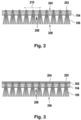
- Fig. 2 illustrates a portion of the carrier mesh 104 at location 110 in the system 100 after exiting the fiber inserter 102, according to an embodiment of the invention.
- the carrier mesh 104 includes fibers 106 that have been tufted into the carrier mesh 104. It can be seen that a small loop of tuft fiber 202 extends (i.e., is exposed) on a backside 204 of the carrier mesh 104. Each series of the most closely spaced exposed tuft fibers 202 form a tuft row 210. The distance between two tuft rows can be, for example, 0.2 cm to 2.0 cm, e.g. about 0.25 cm, 0.5 cm or 1.0 cm.
- the tufted fibers 106 form a pile surface 206 on a front side 208 of the carrier mesh 104.
- the system 100 includes a dielectric barrier discharge (DBD) device 112 and a control unit 114.
- the control unit 114 is configured to control the DBD device 112 to apply a dielectric barrier (i.e., plasma) discharge to the backside 204 of the carrier mesh 104 as the carrier mesh 104 moves through the DBD device 112 for plasma-activating the backside 204 in preparation for applying a backing layer, also referred to in the art as a secondary backing or secondary backing layer, by a dispensing unit 116.
- a dielectric barrier i.e., plasma
- Fig. 3 illustrates a portion of the carrier mesh at location 119 of the system 100, after exiting the dispensing unit 116, according to an embodiment of the invention.
- Fig. 3 is identical to Fig. 2 , with the additional feature of a backing layer coating 302 (e.g., a polyurethane or a colloidal latex backing layer coating) that has been applied to the plasma-activated backside 204 by the dispensing unit 116.
- the backing layer coating 302 also referred to as a backing layer 302, covers tufted regions (i.e., those regions containing the loops 202), well as the other remaining non-tufted regions of the plasma-activated backside 204 of the carrier mesh 104.
- the dispensing unit 116 is configured to coat the plasma-activated backside 204 of the carrier mesh 104 with a polyurethane or latex 118.
- the latex 118 is a colloidal latex, however, the polyurethane may be applied as a liquid or a foam.
- the dispensing unit 116 is a lick roll including a rotating element 122 used to apply the polyurethane or colloidal latex 118 to the plasma-activated backside 204 of the carrier mesh 104.
- the scope of the invention includes other means of applying the coating 302.
- the dispensing unit 116 is configured as a knife-over-roll dispensing unit (not shown) for first applying the polyurethane or the colloidal latex onto the plasma-activated backside 204 and then leveling the applied material using the conventional knife-over-roll process.
- a knife-over-roll technique is used, the greige good typically has a different orientation, such that the side from which the fibers protrude faces downwards, allowing to apply the liquid backing by pouring or spraying it onto the opposite, upwards-facing side.
- the system 110 may optionally include an anti-blistering applicator 122, configured in one embodiment as a spray bar.
- an anti-blistering applicator 122 configured in one embodiment as a spray bar.
- the scope of the invention covers any apparatus/process of applying a preferably small amount of anti-blistering agent 124 to the polyurethane or colloidal latex coating (i.e., to the backing layer coating 302) on the backside 204 of the carrier mesh 104.
- the applicator 122 is configured to wet a region 126 of the backing layer 302 with the anti-blistering agent 124.
- Th system optionally includes a heater 128.
- the heater has an entrance 130 and an exit 132.
- the applicator 122 may be configured such that the wet region 126 is a distance 134 from the entrance 130 of the heater 128.
- the system 100 is configured to control the distance 134, via moving the heater 128 or the applicator 122, to control the time period between application of the anti-blistering agent 122 to any region of the carrier mesh 104 and entry of this region into the heater 128 via entrance 130. Time periods may vary depending upon ambient environmental conditions, such as ambient temperatures, relative humidity, etc.
- the heater 128 and/or the applicator 122 are configured to be moveably-adjustable along the path of motion of the carrier mesh 104 on the conveyor assembly 107 for adjusting, either manually by an operator or automatically by the system (e.g., by the control unit 114, based upon operator input and/or sensor data), the distance 134.
- the heater 128 is configured to remove water from the backing layer coating 302, thereby curing it for forming a solid backing layer 136.
- the manufacturing of the artificial turf by the system 100 is complete, although in additional optional embodiments, the artificial turf fibers 106 may be trimmed after leaving the heater 128.
- the backing layer coating 302 may cure before reaching the heater 128 and/or applicator 122, as a result of conditions of the ambient environment, which may be controlled by an operator, and/or length of time after being applied by the dispensing unit 116, and thus the manufacturing of the artificial turf by the system 100 is considered complete before reaching the heater 128 or the applicator 122.
- the artificial turf mesh 104 with the integrated fibers 106 and the backing layer 302 exiting the dispensing unit 116 is the manufactured artificial turf of the present invention.
- the artificial turf mesh 104 with the integrated fibers 106 and the backing layer 302 exiting the applicator 122 or the heater 128 is the manufactured artificial turf of the present invention.
- the heater 128 may function in different ways.
- the heater 128 has a first heat control element 138 and a second heat control element 140.
- the first heat control element 138 generates forced air 142 with a first temperature range and the second heat control element 140 generates forced air 144 with a second temperature range.
- the temperature of the backside 204 can be controlled to be different from that of the frontside 206 during the curing process. This may lead to effective removal of water from the backing layer coating 302 while protecting the artificial turf fibers 106 against high temperatures.
- the manufacturing process and the system for manufacturing an artificial turf depicted in figure 1 comprises a fiber inserter 102.
- the artificial turf is manufacture in a roll-to-roll process and the system is free of a fiber inserter 102 or the fiber inserter is not used.
- the manufacturing process described with reference to figure 1 may start with unrolling a roll of greige good (a carrier mesh comprising the already integrated fibers, but being free of a backing layer) and the unrolled greige good is fed into the air gap of the dielectric barrier discharge device.
- the backside of the greige good (opposite to the side from which the fibers protrude) is plasma-activated using a dielectric barrier discharge technique
- the liquid backing is applied onto the plasma-activated backside, optionally dried in an oven, and then rolled up to provide a roll of artificial turf.
- Fig. 4 shows a y-z cross section of the DBD device 112 of Fig. 1 , and the control unit 114, according to an embodiment of the invention.
- the DBD device 112 includes a first electrode 402 and a second electrode 404, and is illustrated with the carrier mesh 104 partially occupying an air gap g 405 formed between the first and second electrodes 402, 404, as discussed further below.
- the first and second electrodes 402, 404 are oriented parallel to one another (i.e., both electrodes are elongated in a same first direction 406, or in other words, have longitudinal axes of symmetry, also referred to as major axes of symmetry, that are oriented in the same first direction).
- the first electrode 402 is adjacent to the backside 204 (also referred to as the backside surface 204) of the carrier mesh 104
- the second electrode 404 is adjacent to the frontside 208 of the carrier mesh 104
- the second electrode 404 is at least partially encased in a dielectric 408.
- the dielectric 408 is formed of (homogeneously-distributed) dielectric plastic material.
- the dielectric extends a width/thickness in at least in a second direction 412 (i.e., in the -z direction) towards the first electrode 402, where the second direction 412 is perpendicular to the first direction 406.
- the air gap g 405 is formed between a bottom edge 413 of the dielectric (i.e., the edge or surface closest to the first electrode 402) and the first electrode. As illustrated, the air gap g 405 is partially occupied by the carrier mesh 104 with the integrated fibers 106, which is being fed though the air gap 405 by the conveyor assembly 107.
- the conveyor assembly 107 is configured to move the carrier mesh 104 with the integrated fibers 106 in a third direction 414 (i.e., into or out of the plane of Fig. 4 ) that is orthogonal to both the first and second directions 406, 412.
- the conveyor assembly 107 transports the carrier mesh 104 through the air gap 405 at a speed between 5-15 m/min, preferably between 6-12 m/min, and more preferably between 6-9 m/min.
- the speed is dependent upon one or more parameters of the dispensing unit 116 (e.g., a rate at which the backing layer 302 is applied to the plasma-activated backside 204 of the carrier mesh 104).
- the conveyor assembly 107 is configured to move the carrier mesh 104 through the air gap 405 at a manually-adjustable and/or an automatically-adjustable speed.
- the speed may be adjusted by operator input to the control unit 114, and/or the control unit 114 may include software that is configured to automatically determine and/or adjust the speed of the conveyor assembly 107 based upon data input by an operator and/or upon data collected from system sensors, e.g., rate of application of the backing layer mixture 118 from the dispensing unit 116 and/or power applied to the backside 204 of the carrier mesh 104 as a plasma discharge from the DBD device 112.
- the system 112 may comprise one or more distance sensors configured to identify if the carrier mesh comprises any elevations or attached objects which might, upon reaching the first electrode, collide and potentially damage the first electrode.
- the controller operatively coupled to the distance sensor(s) to increase the width of the air gap or to stop the movement of the carrier mesh as to prevent the first electrodes being damaged.
- the distance sensors can be, for example, optical sensors, e.g., cameras, or laser-based distance sensors, or ultrasonic signal-based distance sensors, capacitive distance sensors, etc.
- a single electrode i.e., the first electrode 402 of the DBD device 112 is electrically coupled to the control unit 114 via a power lead 416.
- the power lead 114 supplies a voltage to the first electrode, resulting in the DBD device 112 generating a plasma discharge, also referred to as a dielectric barrier discharge, that is directed to (i.e., applied to) the backside 204 of the carrier mesh 104 for plasma-activating the backside 204.
- two or more power leads 416 are coupled between the control unit 114 and two or more positions along the first electrode 402.
- the DBD device 112 includes a support structure 418 that is configured to be non-electrically (e.g., mechanically) coupled to the first electrode 402 at one or more positions along the first electrode 402, or as illustrated, at two end points 420 of the first electrode 402, for supporting a positioning of the first electrode 402 with respect to the second electrode 404 and with respect to the bottom edge 413 of the dielectric 408 that at least partially encases the second electrode 404, and for setting a width of the air gap g 405.
- the support structure 418 is configured to be manually adjustable in at least a vertical direction (i.e., in the z direction 412). Control of the support structure 418 by the control unit 114 will be discussed in more detail further below.
- the thickness of the dielectric 408 is between 0.2 cm to 10.0 cm, e.g., about 2.0-3.0 cm.
- the air gap g 405 has a width which results in a distance rg 424 measured between the backside 204 of the carrier mesh and the first electrode 402 that is typically less than 1.0 cm, e.g. less than 0.5 cm and preferably less than 0.3 cm.
- the distance 424 of the first electrode(s) is chosen such that a direct contact of the first electrode(s) and the carrier mesh is avoided.
- a distance 424 of 0 mm i.e., a basically contact-based configuration of the plasma discharge device, may successfully be used.
- the first electrode 402 also referred to as a counter electrode
- the second electrode 404 and the carrier mesh 104 each have at length 1426 of 4 meters.
- the scope of the invention covers counter electrodes, electrodes and/or carrier meshes having different lengths (i.e., smaller and larger).
- the dielectric 408 is a hollow cylinder (or a partial cylinder) that is centered about and extended along a cylinder of metal used as the second electrode 404.
- the scope of the invention includes dielectrics having other shapes, such as elliptical or rectangular.
- the second electrode 404 including the dielectric 408 surrounds (or at least partially surrounds) the second electrode 404 and is vertically positioned (i.e., positioned in the z direction 412) within the DBD device 112 such that the frontside 206 of the carrier mesh 104 makes contact with the bottom edge 413 (or surface) of the dielectric (i.e., edge (or surface) closest to the first electrode 402) such that the complete cylinder 408 rotates about its longitudinal axis as the carrier mesh 104 is moved through the air gap 405 of the DBD device 112 by the conveyor assembly 107.
- the static frictional force between the frontside 208 of the carrier mesh 104 and the dielectric 408 is large enough to cause the dielectric 408to rotate about the second electrode 404 as the carrier mesh 104 is moved through the air gap 405 of the DBD device 112 by the conveyor assembly 107 without any slippage between the portions of the dielectric 408 in contact with the frontside 208 of the carrier mesh 104 and the frontside 208 of the carrier mesh 104.
- neither the frontside 208 of the carrier mesh 104, nor the dielectric 408 surrounding the second electrode 404 build up a static electrical charge.
- the dynamic frictional forces cause by one material contacting and moving with respect to a second material may generate heat, static electricity, and a static voltage potential between the two materials, thereby compromising a uniform distribution of the dielectric barrier discharge (i.e., the plasma discharge) across the backside 204 of the carrier mesh 104, as well as compromising application of the discharge at desired controlled voltages and/or desired controlled temperatures.
- the dielectric barrier discharge i.e., the plasma discharge
- the control unit 114 includes a controller 426, a positioning system 428, and a power source 430, such as a transformer.
- the controller 426 is configured to control the DBD device 112 for applying a dielectric barrier discharge to the backside 204 of the carrier mesh 104 as the carrier mesh 104 moves through the air gap 405 for plasma-activating the backside 204.
- the controller 426 controls the DBD device 112 to continuously apply a plasma discharge to the backside 204 of the mesh 104 as the mesh 104 moves through the air gap 405.
- the controller 426 is configured to enable the power source 430 to apply, via one or more power switches (not shown), a voltage of up to and including 40 kV to the first electrode 402 of the DBD device 112 via the power lead 416.
- the controller 426 controls the DBD device 112 to continuously apply a plasma discharge to the backside 204 of the mesh 104 as the mesh 104 moves through the air gap 405 at an energy density of between 0.5 J cm 2 and 0.6 J/cm 2 .
- the DBD device 112 delivers the plasma discharge at a power between 500 and 600 Watts as the conveyor assembly 107 moves the mesh at a speed of 6 m/min for applying an energy density of between 0.5 J cm 2 and 0.6 J/cm 2 to the backside 204 of the mesh 104.
- the energy density can be adjusted by controlling the speed of the conveyor assembly 107 and the applied power. For example, decreasing the applied power and/or increasing the conveyor speed reduces the energy density applied to the backside 204 of the mesh 104.
- control unit 114 is configured to control the dielectric barrier discharge device 122 to apply the dielectric barrier discharge for plasma-activating the backside 204 by enabling the formation of covalent bonds between the backside 204 and the backing layer coating 302, as applied by the dispensing unit 116 after the backside 204 is plasma-activated, for providing increased binding between the fibers 106 of the carrier mesh 104 and the applied backing layer 302.
- the portions of the fibers exposed on the backside of the carrier mesh e.g., for fibers tufted into the carrier mesh, as illustrated by Fig.
- portions of the fibers 202 exposed in the tuft rows 210 on the backside of the carrier mesh are activated by the plasma discharge (i.e., by the bombardment of the mesh backside 204 (i.e., the backside surface) by high energy ions from the plasma formed in the air gap 405), or in other words, enabling the mesh backside 204 (at an atomic/molecular level) to be receptive to the formation of covalent bonds with the backing layer 302, which is applied shortly thereafter.
- the dielectric 408 of the DBD device 112 limits current flow and distributes the plasma discharge more uniformly over the backside 204 of the carrier mesh 104, thereby enabling the formation of a more homogeneous distribution of covalent binding between the backside 204 and applied backing layer 302, resulting in an overall improvement in the strength of attachment between the backing layer 302 and the fibers 106 of the carrier mesh.
- the system 100 is configured, e.g., via selection of the speed of the conveyor assembly 107 and/or selection of distances between the DBD device 112 and the dispensing unit 116, such that the dispensing unit 116 applies the backing layer coating to a portion of the plasma-activated backside 204 of the carrier mesh 104 within a few hours or preferably a few minutes after plasma activation of that portion by the DBD device 112, so that a significant number of plasma-enhanced receptive sites are still available for forming respective covalent bonds with the backing layer 302 when applied.
- a maximum time period for applying the backing layer 302 to a portion of the plasma-activated backside 204 of the carrier mesh 104 is 5 minutes after plasma activation of that portion by the DBD device 112.
- the positioning system 428 is coupled to the support structure 418 of the DBD device 112 for moving the support structure 418 in at least a vertical up-down direction (in direction 412).
- the positioning system 428 is a distributed positioning system 428 that includes one or more of servos, actuators, switches (mechanical and/or electrical), signal/control lines for transmitting electrical, pneumatic and/or hydraulic control signals for operating the servos and actuators, and sensors, or any combination thereof, distributed throughout the system 100 for moving components of the system 100, such as moving the support structure 418 for adjusting/setting the width of the air gap 405.
- the positioning system 428 is configured to also adjust/set other system parameters, without moving any of the system components, such as adjusting/setting the speed of the conveyor assembly 107 for moving the carrier mesh 104, via control/power signals to electrical motors for driving the conveyor assembly 107.
- the controller 426 may be configured, e.g., with a user input interface, such that an operator may manually enter data that instructs the controller 426 to adjust the air gap 405, via the positioning system 428, to a desired width.
- the desired width of the air gap 405 may be based upon one or more of: the voltage to be applied to the first electrode 402, the speed at which the carrier mesh 104 is moved through the air gap 405, the thickness of the dielectric 408, the type of material of the dielectric 408 and/or carrier mesh 104, the width wc 422 of the carrier mesh, the distance rg 424 measured between the backside 204 of the carrier mesh 104 and the first electrode 402, or the ambient environment of the DBD device 112 (e.g., ambient temperature, humidity, etc.), or any combination thereof.
- the ambient environment of the DBD device 112 e.g., ambient temperature, humidity, etc.
- the controller 426 includes software that is configured to automatically determine a desired width of the air gap 405 based on, e.g., operator input to the controller 426, as described above, and/or on data collected by system sensors (not shown) of the distributed positioning system 428.
- the distribute positioning system 428 may optionally include a motion sensor and/or a width sensor for detecting the speed of the carrier mesh 104 through the air gap 405 and/or the width wc 422 of the carrier mesh 100 integrated with the fibers 106.
- Motion sensors are well known in the art and will not be discussed in further detail.
- a width sensor includes a vertically-moveable mechanical arm that moves in a vertical direction 412 as it remains in contact with the backside 204 of the carrier mesh 104 at a location in the system 100 before the carrier mesh 104 enters the air gap 405. Based on a current vertical position of the moveable arm, a known average width of the carrier mesh 104 integrated with the fibers 106, and the speed of the mesh 104 along the conveyor assembly 107, the controller 426 determines the desired width of the air gap 405 and instructs the positioning system 428 to continuously adjust the air gap width such that the distance rg 424 measured between the backside 204 of the carrier mesh 104 and the first electrode 402 is constant, or essentially constant.
- the controller 426 uses the data received from the width sensor, corrects for width irregularities, thereby ensuring that the distance rg 424 remains essentially at a constant desired value when the plasma discharge is applied to the mesh 104 as the mesh 104 moves through the air gap 405.
- the width sensor of the positioning system 428 is a camera that captures images of either the backside 204 of the carrier mesh 104 or the entire carrier mesh 104 (bounded by the front and backsides 208, 204), as the carrier mesh 104 moves past the camera before the mesh 104 enters the air gap 405.
- the controller 426 receives the captured images, and using, e.g., edge detection software, detects the vertical position of the backside 204 (and/or frontside 208) of the mesh 104, determines width irregularities in the mesh 104, and instructs the positioning system 428 to adjust the position of the first electrode 402 to keep the distance rg 424 at an essentially constant desired value as the mesh 104 moves through the air gap 405 to receive the plasma discharge.
- the system 112 may comprise one or more distance sensors for identifying the distance of elevations or objects which might collide with the first electrode.
- the controller may be configured to adjust the width of the airgap, e.g. via the position of the first electrode, based on the measurement data obtained from the distance sensors, such that a collision is prevented.
- the distance rg 424 is measured between the portions of the fibers elevated above the backside 204 of the mesh 104 (as a result of the fibers being tufted into the mesh 104) and the first electrode 402.
- the backside 204 forms a non-planar surface, where the tuft rows 210 form tufted regions elevated above the other non-tufted regions of the carrier mesh 104.
- the scope of the present invention covers carrier meshes 104 including other types of fiber integration.
- the carrier mesh 104 includes fibers incorporated by weaving the fibers into the carrier mesh.
- the scope of the present invention covers planar and non-planar carrier mesh backsides 204.
- the carrier mesh 104 is positioned on the carrier assembly 107 such that the tuft rows 210 are parallel to the direction of motion of the carrier mesh 104 though the DBD device 112.
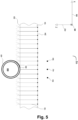
- Fig. 5 shows a z-x cross-sectional view of the DBD device 112 of Fig. 1 , according to an embodiment of the invention.
- Reference numbers that are the same as those used in conjunction with Figs. 1 and 4 reference the same elements.
- the support structure 418 and power lead 416 are not shown.
- the DBD device 112 includes the second electrode 404 surrounded by the dielectric 408, formed as a hollow cylinder of dielectric material having a bottom edge 413 (i.e., portion of dielectric surface) contacting the frontside 208 of the carrier mesh 104.
- the whole cylinder comprising the second electrode and the dielectric is rotatable about the longitudinal axis of the whole cylinder.
- the DBD device 112 includes the first electrode 402, and may optionally include one or more additional first electrodes, all aligned parallel to one another (all longitudinally extended in the same direction).
- the DBD device 112 includes two additional first electrodes 502 and 504.
- the scope of the invention covers other embodiments having any number of parallel oriented first electrodes.
- each of the optional first electrodes 502 and 504 are coupled to the support structural 418 for support and vertical location adjustment, and with the power supply 430 via the power lead 416.
- the first electrodes are galvanically decoupled from each other.
- first electrodes e.g., 402, 502, 504
- plasma activation of the backside 204, as well as binding between the backside 204 and the applied backing layer 302 is increased due to the increase in total surface area provided by the additional first electrodes, resulting in an increase in the volume of air in the portion of the air gap 405 (that is not occupied by the mesh 104, (i.e., the volume contained within the distance rg 424)) that is transformed into a plasma before the transformation is halted by plasma saturation within the air gap. That is, the volume of air in the gap that can be transformed into a plasma is limited by the number of first electrodes, independent of increasing the applied power above a maximum value corresponding to the onset of plasma saturation.
- a DBD device including one first electrode may result in maximum binding at 600 Watts, with no appreciable improvement in binding at powers greater than 600 Watts.
- a DBD device having two or more first electrodes operating at 600 Watts has a greater volume of air in the gap before plasma saturation of the gap occurs, and thus an improvement in binding at 600 Watts in comparison, and a possible additional improvement in binding for powers greater the 600 Watts up to a higher maximum power limit.
- a further advantage may be that in case the voltage field of one first electrode partially breaks down or is reduced due to a contact with the carrier mesh and a resulting partial discharge, the voltage field to the other first electrode(s) remains unaffected, thereby ensuring that the plasma-activation is
- a system of the present invention includes the dielectric barrier discharge device 112, the conveyor assembly 107, the control unit 114 and the dispensing unit 116 of Fig. 1 , either formed as a separate production line system independent of the production line system 100, or formed as a system including the individual components 112, 107, 114, and 116 (or alternatively the individual components 112, 114 and 116) configured not as a production line or part of a production line.
- Fig. 6 shows an overhead perspective view of the DBD device 112 of Fig. 1 , according to an embodiment of the invention.
- the DBD device 112 includes two first electrodes 602, 604, where each first electrode is the same as the first electrode 402 ( Fig. 4 ), the dielectric 408 formed as a cylinder that completely surrounds (i.e., encases) the second electrode 404, which is not visible, and the air gap 405 through which the carrier mesh 104 (not shown) is moved.
- the two first electrodes 602, 604 preferably are parallel metal wires galvanically decoupled from each other.
- Fig. 7 illustrates a method 700 for method of manufacturing an artificial turf, according to an embodiment of the invention.
- a carrier mesh 104 is moved through an air gap 405 formed between a first electrode 402 and a second electrode 404 of a dielectric barrier discharge device 112.
- the carrier mesh 104 includes a backside 204, and the carrier mesh 104 includes fibers 106 integrated such that a portion 202 of the fibers 106 are exposed on the backside 204.
- step 704 a dielectric barrier discharge is applied to the backside 204 of the carrier mesh 104 for plasma-activating the backside 204.
- the liquid polyurethane backing was applied and solidified in an oven. Then, the tuft withdrawal force was measured. Some measurements were performed 24 h after the manufacturing process. Other tuft withdrawal force measurements were performed after 14 days of immersing the sample in a 70 °C water-bath (simulated aging) or after 4 weeks (incubation in dry state, no water-bath). The time point of performing the respective measurement is also indicated in the column "sample fiber type”.
- the tuft withdrawal force measurements were performed as specified in FIFA "Test Method 26" (Test Manual I - Test Methods: 2015 Edition - FIFA Quality Programme for Football Turf), page 81.
- the FIFA test 26 comprises selecting and withdrawing one whole tuft and measure the force required to completely withdraw the tuft along a predefined path.
- the average and standard deviation were computed for the measurement values obtained for each section of the first and the four other artificial turfs.
- the average force required to pull out a fiber from the carrier mesh in the plasma activated section is 56 N 24 h after the manufacturing
- the average force required to pull out a fiber from the carrier mesh in the non-plasma activated control sections is 34 and 37 N 24 h after the manufacturing of the first artificial turf.
- the measurements were repeated after 14 days of aging in a 70°C water bath and after 4 weeks after manufacturing (storing the artificial turf in dry state, no water-bath).
- the water-based aging process comprised immersing the five artificial turfs in hot water (70°C) in accordance with DIN EN 13744.
- the artificial turf to be tested is to be completely immersed in a water bath having a temperature of 70°C plus/minus 2 °C for 334 to 338 hours (14 days). Then, the artificial turf sections to be tested were taken out of the water and prepared for performing a tuft withdrawal force test as specified in FIFA "Test Method 26" (Test Manual I - Test Methods: 2015 Edition - FIFA Quality Programme for Football Turf), page 81.
- the measurement results show that the fibers of the plasma-activated sections of the artificial turfs are bound more strongly to the backing-layers in comparison to the fibers of the control sections (non-activated sections), with the rate of increase in tuft-binding per unit applied power decreasing as the applied power approaches 700 Watts.
- a further increase in applied power results in negligible increase in tuft-binding, due to plasma-saturation of the gap.
- a long-time test for the turf number 3 for the section treated with 700 Watt was performed seven weeks after production (not shown).
- the tuft withdrawal force obtained after seven weeks was basically identical to the tuft withdrawal forces measured after two weeks, showing that the plasma activation resulted in a stable, long-lasting enhancement of the tuft bind.
Landscapes
- Engineering & Computer Science (AREA)
- Physics & Mathematics (AREA)
- Plasma & Fusion (AREA)
- Spectroscopy & Molecular Physics (AREA)
- Textile Engineering (AREA)
- Architecture (AREA)
- Civil Engineering (AREA)
- Structural Engineering (AREA)
- Chemical Or Physical Treatment Of Fibers (AREA)
Priority Applications (14)
| Application Number | Priority Date | Filing Date | Title |
|---|---|---|---|
| EP23198798.3A EP4529362A1 (fr) | 2023-09-21 | 2023-09-21 | Gazon artificiel et procédé de fabrication |
| US18/480,089 US20250101678A1 (en) | 2023-09-21 | 2023-10-03 | Artificial turf and method of manufacturing |
| US18/489,393 US20250100001A1 (en) | 2023-09-21 | 2023-10-18 | System for artificial turf manufacturing |
| PCT/EP2024/069928 WO2025061334A1 (fr) | 2023-09-21 | 2024-07-12 | Système de fabrication de gazon artificiel |
| PCT/EP2024/069927 WO2025061333A1 (fr) | 2023-09-21 | 2024-07-12 | Gazon artificiel et procédé de fabrication |
| PCT/EP2024/076212 WO2025061822A1 (fr) | 2023-09-21 | 2024-09-19 | Système de fabrication de gazon artificiel |
| AU2024345030A AU2024345030A1 (en) | 2023-09-21 | 2024-09-19 | Artificial turf and method of manufacturing |
| PCT/EP2024/076210 WO2025061821A1 (fr) | 2023-09-21 | 2024-09-19 | Gazon artificiel et procédé de fabrication |
| AU2024344580A AU2024344580A1 (en) | 2023-09-21 | 2024-09-19 | System for artificial turf manufacturing |
| US18/861,958 US20260002320A1 (en) | 2023-09-21 | 2024-09-19 | Artificial turf with traction control agent |
| US18/939,903 US20250100002A1 (en) | 2023-09-21 | 2024-11-07 | System for artificial turf manufacturing |
| US18/940,327 US20250100003A1 (en) | 2023-09-21 | 2024-11-07 | Artificial turf with traction control agent |
| US18/941,278 US20250100004A1 (en) | 2023-09-21 | 2024-11-08 | Artificial turf with traction control agent |
| US18/941,425 US20250100005A1 (en) | 2023-09-21 | 2024-11-08 | Artificial turf with traction control agent |
Applications Claiming Priority (1)
| Application Number | Priority Date | Filing Date | Title |
|---|---|---|---|
| EP23198798.3A EP4529362A1 (fr) | 2023-09-21 | 2023-09-21 | Gazon artificiel et procédé de fabrication |
Publications (1)
| Publication Number | Publication Date |
|---|---|
| EP4529362A1 true EP4529362A1 (fr) | 2025-03-26 |
Family
ID=88146914
Family Applications (1)
| Application Number | Title | Priority Date | Filing Date |
|---|---|---|---|
| EP23198798.3A Pending EP4529362A1 (fr) | 2023-09-21 | 2023-09-21 | Gazon artificiel et procédé de fabrication |
Country Status (1)
| Country | Link |
|---|---|
| EP (1) | EP4529362A1 (fr) |
Citations (3)
| Publication number | Priority date | Publication date | Assignee | Title |
|---|---|---|---|---|
| JPS57101078A (en) * | 1980-12-15 | 1982-06-23 | Hiraoka Shokusen | Production of pile carpet |
| US7026031B2 (en) | 2002-12-05 | 2006-04-11 | Bayer Materialscience Llc | Tuft bind of urethane backed artificial turf |
| WO2017162643A1 (fr) * | 2016-03-22 | 2017-09-28 | Polytex Sportbeläge Produktions-Gmbh | Machine de fabrication de gazon artificiel |
-
2023
- 2023-09-21 EP EP23198798.3A patent/EP4529362A1/fr active Pending
Patent Citations (3)
| Publication number | Priority date | Publication date | Assignee | Title |
|---|---|---|---|---|
| JPS57101078A (en) * | 1980-12-15 | 1982-06-23 | Hiraoka Shokusen | Production of pile carpet |
| US7026031B2 (en) | 2002-12-05 | 2006-04-11 | Bayer Materialscience Llc | Tuft bind of urethane backed artificial turf |
| WO2017162643A1 (fr) * | 2016-03-22 | 2017-09-28 | Polytex Sportbeläge Produktions-Gmbh | Machine de fabrication de gazon artificiel |
Non-Patent Citations (1)
| Title |
|---|
| "Test Method 26", TEST MANUAL I - TEST METHODS: 2015 EDITION - FIFA QUALITY PROGRAMME FOR FOOTBALL TURF, pages 81 |
Similar Documents
| Publication | Publication Date | Title |
|---|---|---|
| DE602006000507T2 (de) | Verfahren und Vorrichtung zur Messung des Flächengewichts und des Feuchtegehalts einer Schicht, z.B. aus Papier, unter Verwendung dielektrischer Resonatoren | |
| CN103026450B (zh) | 通用射束干扰侦测系统 | |
| DE3623441C2 (de) | Ladungsdichtedetektor für Strahlenimplantation | |
| DE60018125T2 (de) | Steurung der Ionendosis in einem Implantierungsgerät | |
| EP4529362A1 (fr) | Gazon artificiel et procédé de fabrication | |
| DE69920827T2 (de) | Verfahren zur Messung der Verteilung von Ladungsträgerteilchenstrahlen und dazu gehörigen Verfahren | |
| EP4528031A1 (fr) | Système de fabrication de gazon artificiel | |
| US20250101678A1 (en) | Artificial turf and method of manufacturing | |
| DE69721029T2 (de) | Kontrollvorrichtungen für die dosisüberwachung in ionenimplantierungsgeräte | |
| US20250100001A1 (en) | System for artificial turf manufacturing | |
| DE112008002883T5 (de) | Kohlenstoffmaterial-Dosimeter | |
| US20260002320A1 (en) | Artificial turf with traction control agent | |
| WO2025061334A1 (fr) | Système de fabrication de gazon artificiel | |
| US20230323559A1 (en) | Facility for powder impregnation of at least one yarn and/or ribbon type substrate to be treated | |
| WO2009002665A1 (fr) | Appareil et procédés pour la modification de charge électrostatique sur une bande en défilement | |
| EP0139901B1 (fr) | Procédé et appareil pour la fabrication de surfaces floqués structurés | |
| DE69414659T2 (de) | Gerät und Verfahren zur Ionenimplantierung | |
| DE69313211T2 (de) | Verfahren und Vorrichtung zur Coronabehandlung | |
| JP3517968B2 (ja) | 絶縁性ウエブの除電方法およびウエブの製造方法 | |
| EP1088242B1 (fr) | Procede et dispositif pour determiner la densite de tabac par resonance magnetique nucleaire | |
| WO2008083699A1 (fr) | Système de production d'un produit plat de type réticulaire ou en treillis | |
| Zhu et al. | Methodological investigation on photo-stimulated discharge to obtain accurate trap information in polymer dielectrics | |
| Foulon-Belkacemi et al. | Conduction and charge-injection in polypropylene films aged by corona discharge with streamers | |
| Kamenitsa et al. | Sources of variation in Therma Wave measurements of ion implanted wafers | |
| DE2202828C2 (de) | Verfahren und Anlage zum kontinuierlichen elektrostatischen Spreizen von aufgespleißten Flächengebilden |
Legal Events
| Date | Code | Title | Description |
|---|---|---|---|
| PUAI | Public reference made under article 153(3) epc to a published international application that has entered the european phase |
Free format text: ORIGINAL CODE: 0009012 |
|
| STAA | Information on the status of an ep patent application or granted ep patent |
Free format text: STATUS: REQUEST FOR EXAMINATION WAS MADE |
|
| 17P | Request for examination filed |
Effective date: 20250122 |
|
| AK | Designated contracting states |
Kind code of ref document: A1 Designated state(s): AL AT BE BG CH CY CZ DE DK EE ES FI FR GB GR HR HU IE IS IT LI LT LU LV MC ME MK MT NL NO PL PT RO RS SE SI SK SM TR |