EP4529762A1 - Dispositif de maintien pour l'élevage d'animaux aviaires, abri pour animaux aviaires et utilisation - Google Patents
Dispositif de maintien pour l'élevage d'animaux aviaires, abri pour animaux aviaires et utilisation Download PDFInfo
- Publication number
- EP4529762A1 EP4529762A1 EP24198741.1A EP24198741A EP4529762A1 EP 4529762 A1 EP4529762 A1 EP 4529762A1 EP 24198741 A EP24198741 A EP 24198741A EP 4529762 A1 EP4529762 A1 EP 4529762A1
- Authority
- EP
- European Patent Office
- Prior art keywords
- rearing
- grid
- guide rail
- rail section
- level
- Prior art date
- Legal status (The legal status is an assumption and is not a legal conclusion. Google has not performed a legal analysis and makes no representation as to the accuracy of the status listed.)
- Pending
Links
Images


Classifications
-
- A—HUMAN NECESSITIES
- A01—AGRICULTURE; FORESTRY; ANIMAL HUSBANDRY; HUNTING; TRAPPING; FISHING
- A01K—ANIMAL HUSBANDRY; AVICULTURE; APICULTURE; PISCICULTURE; FISHING; REARING OR BREEDING ANIMALS, NOT OTHERWISE PROVIDED FOR; NEW BREEDS OF ANIMALS
- A01K31/00—Housing birds
- A01K31/002—Poultry cages, e.g. transport boxes
- A01K31/005—Battery breeding cages, with or without auxiliary features, e.g. feeding, watering, demanuring, heating, ventilation
-
- A—HUMAN NECESSITIES
- A01—AGRICULTURE; FORESTRY; ANIMAL HUSBANDRY; HUNTING; TRAPPING; FISHING
- A01K—ANIMAL HUSBANDRY; AVICULTURE; APICULTURE; PISCICULTURE; FISHING; REARING OR BREEDING ANIMALS, NOT OTHERWISE PROVIDED FOR; NEW BREEDS OF ANIMALS
- A01K31/00—Housing birds
- A01K31/18—Chicken coops or houses for baby chicks; Brooders including auxiliary features, e.g. feeding, watering, demanuring, heating, ventilation
- A01K31/19—Brooders ; Foster-mothers; Hovers
-
- A—HUMAN NECESSITIES
- A01—AGRICULTURE; FORESTRY; ANIMAL HUSBANDRY; HUNTING; TRAPPING; FISHING
- A01K—ANIMAL HUSBANDRY; AVICULTURE; APICULTURE; PISCICULTURE; FISHING; REARING OR BREEDING ANIMALS, NOT OTHERWISE PROVIDED FOR; NEW BREEDS OF ANIMALS
- A01K31/00—Housing birds
- A01K31/22—Poultry runs ; Poultry houses, including auxiliary features, e.g. feeding, watering, demanuring
-
- A—HUMAN NECESSITIES
- A01—AGRICULTURE; FORESTRY; ANIMAL HUSBANDRY; HUNTING; TRAPPING; FISHING
- A01K—ANIMAL HUSBANDRY; AVICULTURE; APICULTURE; PISCICULTURE; FISHING; REARING OR BREEDING ANIMALS, NOT OTHERWISE PROVIDED FOR; NEW BREEDS OF ANIMALS
- A01K31/00—Housing birds
- A01K31/02—Door appliances; Automatic door-openers
Definitions
- the invention relates to a rearing and housing facility for the tiered rearing of poultry, in particular a rearing aviary, having at least a first rearing level and a second rearing level which is arranged above the first rearing level, wherein the rearing levels are designed to keep the poultry, and wherein the first rearing level has a first lateral opening to at least one side of the rearing and housing facility and the second rearing level has a second lateral opening to that side, and a door arrangement for closing the openings.
- Such rearing and housing devices are known from the prior art. They are used for the so-called tiered rearing of poultry. This means that the poultry are kept on individual rearing levels depending on their growth stage, or side openings of the rearing levels are released by opening closure means, allowing the birds to leave the housing facility and move between the individual rearing levels or even to a floor below the housing facility.
- opening closure means allowing the birds to leave the housing facility and move between the individual rearing levels or even to a floor below the housing facility.
- To close the side openings of the rearing levels it is known to use folding grids, folding grids, or sliding grids as closure means. These are provided separately for the individual rearing levels and are designed to close the relevant side openings.
- the object of the invention was to further develop a rearing and housing facility of the type described above in such a way that the disadvantages identified in the prior art are eliminated as far as possible.
- the aim was to provide a rearing and housing facility with a door arrangement that is flexibly configurable and offers high ease of use, as well as with minimal or no impairment of the accessibility of the poultry.
- the object is achieved in a rearing housing device of the type mentioned above in that the door arrangement has a closure means that is arranged vertically displaceably relative to the two openings and is configured to open or close the first opening, the second opening, and both openings.
- the first opening is, so to speak, a lower opening, and the second opening an upper opening of the rearing housing device.
- the invention utilizes the finding that, by using a single vertically movable closure means in the manner of a door or gate, the lateral openings of both rearing levels can be flexibly opened and closed. For example, positioning the closure means such that both openings are exposed allows vaccinating personnel to more easily remove the animals from the facility during capture and vaccination. Since the closure means is completely removed from the area of the two openings to the rearing levels, there are no barriers for the personnel, and they can partially or completely enter the housing facility if necessary. In an operating scenario in which only the second, upper opening is closed by the closure means, it is ensured that the young animals cannot jump from the upper rearing level down to a floor below the housing facility and thereby possibly injure themselves.
- the closure means is positioned in such a way that both openings are closed, it can be ensured that the poultry, particularly in the initial phase of the rearing process, cannot reach the floor below the housing facility.
- the requirements of tiered rearing for the operating staff can be met particularly flexibly using a single closure means.
- the accessibility of the housing facility as a whole is significantly increased. This is particularly because the closure means can preferably be moved completely out of the area of the lateral openings.
- the door assembly has a guide assembly for guiding the closure means, wherein the guide assembly is arranged on a base frame of the holding device.
- the guide assembly reliably ensures that the closure means can be moved relative to the openings. Furthermore, the arrangement on the base frame achieves a particularly space-saving design of the guide assembly.
- the guide arrangement comprises oppositely arranged guide rails on which the closure means is displaceably guided.
- the guide rails adjacent to the lateral openings, comprise a substantially vertical guide rail section configured to guide the closure means for closing and releasing the lateral opening. Guiding the closure means by means of guide rails enables secure guidance of the guide means, wherein the guide means is easily displaceable by the operator and ensures that the poultry are kept in the respective rearing level when the lateral openings are closed.
- the guide rails have a substantially horizontal guide rail section on the upper side of the base frame, which is particularly dimensioned such that the closure means can be completely accommodated in the horizontal guide rail section.
- the horizontal guide rail section arranged on the upper side of the base frame allows the closure means to be moved into a rest position, in particular when the lateral openings are to be completely exposed, in which the closure means is arranged in such a way that it does not or only slightly restricts the accessibility of the housing facility.
- the closure means can be displaced from the substantially vertical guide rail section to the substantially horizontal guide section and vice versa.
- the guide rails comprise a curved guide rail section between the substantially vertical guide rail section and the substantially horizontal guide rail section, which connects the vertical guide rail section to the horizontal guide rail section.
- the closure means can advantageously be transferred from the horizontal guide rail section to the vertical guide rail section and vice versa.
- the closure means can be transferred between the operating positions more easily and with greater operating comfort.
- the closure means is designed as a grid.
- the use of a grid has proven particularly effective for keeping the poultry safely in the respective rearing levels, while simultaneously ensuring visibility of the rearing levels and ventilation.
- the grid is coated, in particular with zinc-aluminum. This improves corrosion protection and thus increases the service life of the grid.
- the grille is formed from at least two grille segments, wherein the at least two grille segments are connected by means of a connecting means and are in particular movable, in particular pivotable, relative to one another.
- the grille is thus designed in a manner similar to a sectional door.
- the connecting means are configured to reversibly connect the grille segments, in particular by means of a locking mechanism, and to release a connection between the grille segments. The mobility or pivotability ensures that the grille can follow the course of the guide rails.
- the grid segments can thus form grid sections, for example, a first A grid section, formed from several grid segments, can be used to close the side opening of the lower rearing level and a second grid section, which also preferably consists of several grid segments, can be transferred, for example, into the horizontal guide section so that grid sections that are not needed in this configuration can be stowed in this position.
- a first A grid section formed from several grid segments
- a second grid section which also preferably consists of several grid segments
- each grid segment is assigned at least two laterally opposing guide means, by means of which the grid segment is guided along the opposing guide rails.
- the guide means in particular, comprise pins that encompass the guide rails on both sides.
- the grid segments are securely guided along the guide rails.
- the guide means are designed such that they can also be easily guided along the curved guide rail section, so that the grid as a whole can be moved from the vertical guide rail section to the horizontal guide rail section and vice versa, as well as within the respective guide rail sections.
- the connecting means for two adjacent grid segments are formed on the guide means.
- the guide means essentially has two functions: Firstly, it serves to guide the grid segments relative to the guide rails and, furthermore, to establish a reversible connection to an adjacent grid segment. This functional integration allows the total number of parts to be reduced.
- a stop is assigned to the guide rails, which limits the range of movement of the grille in the vertical guide rail section and/or the horizontal guide rail section. This ensures that the grille does not inadvertently leave the respective guide rail section and is securely held within the desired range of movement.
- the rearing levels each have a lateral opening to at least one second side
- the housing device has a second door arrangement with a closure means which is received so as to be vertically displaceable relative to the two openings and is designed to open or close the first, in particular lower, opening, the second, in particular upper, opening and both openings.
- the second side is arranged opposite the first side.
- the second door arrangement utilizes the same advantages and preferred embodiments as the first door arrangement. To avoid repetition, reference is made to the above explanations.
- the device becomes accessible from both sides.
- the horizontal guide sections of the first door assembly and the second door assembly are arranged at a distance from one another and one above the other on the upper side of the base frame. In this way, the closure means or grilles of the two door assemblies can overlap in the upper region of the housing device, thereby achieving a particularly space-saving design.
- the housing facility has a plurality of lateral openings in each of the first rearing level and the second rearing level, with a door arrangement with a closure means being provided for each adjacent lateral opening of the first rearing level and the second rearing level.
- a door arrangement with a closure means being provided for each adjacent lateral opening of the first rearing level and the second rearing level.
- the invention has been described above with reference to a mounting device.
- the invention relates to a method for configuring a mounting device according to at least one of the above embodiments.
- the invention achieves the object described above with respect to the method with the steps: positioning the grid such that the lateral openings are open, and/or positioning the grid such that the lateral opening of the first rearing level is closed and the lateral opening of the second rearing level is open, and/or positioning the grid such that both lateral openings of the first rearing level and the second rearing level are closed, and/or dividing the grid into grid sections and moving grid sections of the grid such that the lateral opening of the second rearing level is closed and the lateral opening of the first rearing level is open.
- the method makes use of the same advantages and preferred embodiments as the housing device according to the invention and vice versa.
- the invention relates to a poultry house for rearing poultry, in particular a pullet house.
- the invention achieves the object described above with respect to the poultry house in that it comprises a rearing and housing facility according to at least one of the above embodiments.
- the poultry house also utilizes the same advantages and preferred embodiments as the housing facility and the method according to the invention, and vice versa. In this regard, reference is made to the above statements, and their content is incorporated herein.
- the invention relates to the use of a rearing/housing device according to at least one of the preceding embodiments for rearing poultry, in particular pullets, in a poultry house, preferably in a poultry house according to one of the preceding claims.
- This use also utilizes the same advantages and preferred embodiments as the housing device according to the invention, the method according to the invention, the poultry house according to the invention, and vice versa.
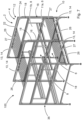
- the Figures 1 - 7 show a poultry house 100 for rearing poultry, which is in Fig. 1 is shown schematically.
- the poultry house 100 is a pullet house.
- the poultry house 100 comprises, with reference to Fig. 1 a rearing and housing facility 2.
- the rearing and housing facility 2 serves for the staged rearing of poultry and is designed in particular as a rearing aviary 2.
- the rearing and housing facility 2 has a base frame 4.
- a first rearing level 6 and a second rearing level 8 are formed or accommodated on the base frame 4.
- the second rearing level 8 is arranged above the first rearing level 6.
- the rearing levels 6, 8 are designed to house the poultry.
- each rearing level 6, 8 is open to at least one side 10 of the rearing and housing facility via a respective lateral opening 11a, 11b.
- each rearing level 6, 8 has openings 11a of the first rearing level 6 and 11b of the second rearing level 8 arranged adjacent to one another.
- the rearing housing device 2 has a door arrangement 12 with a closure means 13, wherein the closure means 13 is accommodated so as to be vertically displaceable relative to the two openings 11a, 11b and is designed to open or close the first, lower opening 11a, the second, upper opening 11b or both openings 11a, 11b simultaneously.
- Fig. 1 In the operating state shown, both openings 11a, 11b are released by the closure means 13.
- the door assembly 12 further comprises a guide assembly 16 for guiding the closure means 13.
- the guide assembly 16 is arranged on the base frame 4 of the holding device 2.
- the door arrangement is detailed for the side openings 11a, 11b shown on the right in the figure.
- the guide arrangement 16 has oppositely arranged guide rails 18.
- the closure means 13 is slidably guided on the guide rails 18.
- the guide rails 18 have a substantially vertical guide rail section 20 adjacent to the lateral openings 11a, 11b.
- the substantially vertical guide rail section 20 is designed to guide the closure means 13 for closing and opening the lateral openings 11a, 11b.
- the guide rails 18 further have a substantially horizontal guide rail section 22 on the upper side of the base frame 4.
- the substantially horizontal guide rail section 22 is dimensioned and designed to completely accommodate the closure means 13 in the horizontal guide rail section 22. This state is shown in Fig. 1 shown. Here it can be seen that the upper horizontal guide rail section 22 can completely accommodate the closure means 13, so that the closure means is accommodated horizontally and above the second rearing level 8.
- the guide rails 18 further comprise a curved guide rail section 24 between the substantially vertical guide rail section 20 and the substantially horizontal guide rail section 22.
- the curved guide rail section 24 connects the vertical guide rail section 20 to the horizontal guide rail section 22.
- the curved guide rail section 24, which is formed on both opposite guide rails 18, allows the closure means 13 to be particularly can be moved back and forth comfortably between the horizontal guide rail section 22 and the vertical guide rail section 20.
- the closure means 13 is designed as a grid 14.
- the grid 14 consists of several grid segments 26, wherein two grid segments 26 are connected by means of a connecting means 28, as shown in the Figures 2 and 4 and 5.
- the connecting means 28 are designed to reversibly connect the grid segments 26 to one another, in particular by means of a locking mechanism 32, and to reversibly release a connection between the grid segments 26.
- the grid segments 26 can be joined together to form a grid 14 and, in addition, to form individual grid sections 27, as in Fig. 7 is shown.
- each grid segment 26 is assigned two laterally opposing guide means 30.
- the respective grid segment 26 is guided in the opposing guide rails 18 by means of the guide means 30.
- the guide means 30 have, in particular, two opposing guide pins 40 that are in contact with opposite sides of the guide rails 18, so that the guide means 30 are securely guided on the guide rails 18.
- the connecting means 28 for two adjacent grid segments 26 are formed on the guide means 30.
- the guide means 30 thus fulfill two functions in a sense. On the one hand, they serve to guide the grid segments 26 relative to the guide rails 18, and on the other hand, they reversibly connect adjacent grid segments 26 to one another.
- the adjacent grid segments 26 are also guided relatively pivotably or rotatably within the connecting means 28, so that the grid 14 as a whole can pass the curved guide rail section 24, as in Fig. 4 is shown, without the connection of the grid segments 26 being dissolved thereby.
- a stop 34 is assigned to the guide rails 18.
- the stop 34 limits a range of movement of the grille 14 in the vertical guide rail section 20 and/or the horizontal guide rail section 22. In this way, it is ensured that the grille 14 remains securely in contact with the guide rails 18 and remains in the intended range of movement.
- the rearing levels 6, 8 each have at least one on a second side 36 opposite the first side 10, in particular two lateral openings 37a, 37b.
- the housing device 2 has at least one, in particular two second door assemblies 38 with a closure means 39, wherein the closure means 39 is received so as to be vertically displaceable relative to the two openings 37a, 37b and is designed to open or close the first, lower opening 37a, the second, upper opening 37b and both openings 37a, 37b.
- two lateral openings 11a in the first rearing level 6 and two lateral openings 11b in the second rearing level 8 are provided on each side 10, 36.
- a door assembly 12 is assigned to the respectively adjacent lateral openings 11a, 11b.
- a second door assembly is assigned to each adjacent lateral openings 37a, 37b.
- the horizontal guide rail sections 22 of the door assembly 12 and the second door assembly 38 run in particular parallel to each other and one above the other, as in Fig. 1 In this way, the grids 14 or closure means 13 can be moved parallel to each other in an area above the second rearing level 8 into a rest position, as in Fig. 1 represented, spent.
- Fig. 1 In the operating state shown, in which the grids 14 are fully open and arranged in an upper, horizontal area of the horizontal guide rail sections 22, vaccination personnel can particularly well catch and vaccinate the animals accommodated in the rearing housing facility 2.
- the door arrangement 12 hardly creates any barriers for the personnel.
- FIG. 3 The closed state of the door arrangements 12 shown in the figure prevents the animals from reaching a floor below the rearing housing device 2.
- the Fig. 6 In the state shown, in which the grid 14 or the closure means 13 is partially located in both the vertical guide rail section 20, the horizontal guide rail section 22 and the curved guide rail section 24, the first rearing level 6 is released and the upper rearing level is closed.
Landscapes
- Life Sciences & Earth Sciences (AREA)
- Environmental Sciences (AREA)
- Birds (AREA)
- Zoology (AREA)
- Animal Husbandry (AREA)
- Biodiversity & Conservation Biology (AREA)
- Housing For Livestock And Birds (AREA)
Applications Claiming Priority (1)
| Application Number | Priority Date | Filing Date | Title |
|---|---|---|---|
| LU505136 | 2023-09-20 |
Publications (1)
| Publication Number | Publication Date |
|---|---|
| EP4529762A1 true EP4529762A1 (fr) | 2025-04-02 |
Family
ID=88147081
Family Applications (1)
| Application Number | Title | Priority Date | Filing Date |
|---|---|---|---|
| EP24198741.1A Pending EP4529762A1 (fr) | 2023-09-20 | 2024-09-05 | Dispositif de maintien pour l'élevage d'animaux aviaires, abri pour animaux aviaires et utilisation |
Country Status (6)
| Country | Link |
|---|---|
| US (1) | US12557791B2 (fr) |
| EP (1) | EP4529762A1 (fr) |
| JP (1) | JP2025048805A (fr) |
| CN (1) | CN119655197A (fr) |
| AU (1) | AU2024219450B2 (fr) |
| CA (1) | CA3254158A1 (fr) |
Cited By (1)
| Publication number | Priority date | Publication date | Assignee | Title |
|---|---|---|---|---|
| WO2026068004A1 (fr) * | 2024-09-26 | 2026-04-02 | Kuehlmann Franz Josef | Installation d'élevage de volailles comprenant une porte actionnée par traction |
Citations (3)
| Publication number | Priority date | Publication date | Assignee | Title |
|---|---|---|---|---|
| US4020793A (en) * | 1975-12-29 | 1977-05-03 | B & J Machinery Co., Inc. | Apparatus and method for raising and transporting poultry |
| EP1813147A2 (fr) * | 2006-01-31 | 2007-08-01 | Van de Ven Beheer B.V. | Dispositif d'élevage pour volaille |
| DE102011087012A1 (de) * | 2011-11-24 | 2013-05-29 | Jan Kreyer | Schiebegitter für eine Aufzuchtvoliere |
Family Cites Families (7)
| Publication number | Priority date | Publication date | Assignee | Title |
|---|---|---|---|---|
| US3389687A (en) * | 1965-08-12 | 1968-06-25 | Harry B. Trussell | Poultry breeding apparatus |
| FR2048109A5 (fr) * | 1969-06-02 | 1971-03-19 | Bekaert Sa Nv | |
| US4905628A (en) * | 1988-01-26 | 1990-03-06 | Quail Roost Quail Farms | Pen for roosting fowl |
| DE102011057174B4 (de) * | 2011-12-29 | 2013-09-05 | Farmer Automatic Gmbh & Co. Kg | Geflügelkäfig mit beweglicher Tür |
| DE202014103037U1 (de) * | 2014-07-02 | 2014-07-15 | Meller Anlagenbau Gmbh | Aufzuchtvoliere |
| DE102019103204A1 (de) * | 2019-02-08 | 2020-08-13 | Fit Farm Innovation Team Gmbh | Verfahren zur Haltung von Legehennen, Volierenhaltungs- und Stallungssystem |
| CN112704029B (zh) * | 2020-12-31 | 2024-08-23 | 江苏华丽智能科技股份有限公司 | 一种新型的笼门结构 |
-
2024
- 2024-09-05 EP EP24198741.1A patent/EP4529762A1/fr active Pending
- 2024-09-06 AU AU2024219450A patent/AU2024219450B2/en active Active
- 2024-09-06 CA CA3254158A patent/CA3254158A1/en active Pending
- 2024-09-17 US US18/887,563 patent/US12557791B2/en active Active
- 2024-09-18 CN CN202411297779.8A patent/CN119655197A/zh active Pending
- 2024-09-19 JP JP2024162339A patent/JP2025048805A/ja active Pending
Patent Citations (3)
| Publication number | Priority date | Publication date | Assignee | Title |
|---|---|---|---|---|
| US4020793A (en) * | 1975-12-29 | 1977-05-03 | B & J Machinery Co., Inc. | Apparatus and method for raising and transporting poultry |
| EP1813147A2 (fr) * | 2006-01-31 | 2007-08-01 | Van de Ven Beheer B.V. | Dispositif d'élevage pour volaille |
| DE102011087012A1 (de) * | 2011-11-24 | 2013-05-29 | Jan Kreyer | Schiebegitter für eine Aufzuchtvoliere |
Cited By (1)
| Publication number | Priority date | Publication date | Assignee | Title |
|---|---|---|---|---|
| WO2026068004A1 (fr) * | 2024-09-26 | 2026-04-02 | Kuehlmann Franz Josef | Installation d'élevage de volailles comprenant une porte actionnée par traction |
Also Published As
| Publication number | Publication date |
|---|---|
| JP2025048805A (ja) | 2025-04-03 |
| AU2024219450A1 (en) | 2025-04-03 |
| US12557791B2 (en) | 2026-02-24 |
| AU2024219450B2 (en) | 2026-03-05 |
| CN119655197A (zh) | 2025-03-21 |
| CA3254158A1 (en) | 2025-06-03 |
| US20250089686A1 (en) | 2025-03-20 |
Similar Documents
| Publication | Publication Date | Title |
|---|---|---|
| DE102006002908B3 (de) | Partikeltherapie-Anlage mit drehbarer Gantry und verfahrbaren Bodensegmenten | |
| EP4529762A1 (fr) | Dispositif de maintien pour l'élevage d'animaux aviaires, abri pour animaux aviaires et utilisation | |
| DE102015202327A1 (de) | Diagnose- und/oder Therapieeinrichtung | |
| DE102018208588A1 (de) | Installation einer Aufzugsanlage mit Linearmotor | |
| EP2005820B1 (fr) | Porte, comme en particulier une porte d'entrée d'une boîte de ramassage automatique pour animaux | |
| DE3871563T2 (de) | Zutrittvorrichtung fuer vieh. | |
| EP4341521B1 (fr) | Système de porte coulissante destiné à l'installation dans un mur de bâtiment et procédé d'entretien d'un système de porte coulissante | |
| EP2842416B1 (fr) | Loge de mise bas dotée de cage de mise bas | |
| DE202023105483U1 (de) | Aufzucht-Haltungseinrichtung zur Aufzucht von Geflügeltieren, betreffender Geflügeltierstall und Verwendung | |
| EP3231960B1 (fr) | Barrière de sécurité installée pour une transition depuis un ascenseur vers un bâtiment ou un échafaudage | |
| DE102014201687B3 (de) | Teleskopschiebetüranlage | |
| EP4186360B1 (fr) | Dispositif de protection des porcelets pour une loge de mise bas et loge de mise bas correspondante | |
| DE202008014643U1 (de) | Scherenmechanismus | |
| EP4272549A1 (fr) | Cage de mise bas de procelets pour un groupe de cages de mise bas de procelets et groupe de cages de mise bas de procelets associé | |
| EP2859170A1 (fr) | Armoire à volet roulant | |
| DE202022102487U1 (de) | Abferkelbucht für eine Gruppenabferkelbucht sowie betreffende Gruppenabferkelbucht | |
| DE202021106464U1 (de) | Ferkelschutzeinrichtung für eine Abferkelbucht und betreffende Abferkelbucht | |
| DE19813034C1 (de) | Tierkäfig, insbesondere zur Haltung von Sauen | |
| EP0542020B1 (fr) | Dispositif de verrouillage pour meubles à tiroirs | |
| EP3327228B1 (fr) | Dispositif de verrouillage destiné à verrouiller et à emmener au moins deux éléments en forme de plaque montés en coulissement le long d'une première direction de coulissement et d'une seconde direction de coulissement opposée et système de paroi comprenant au moins deux éléments en forme de plaque | |
| DE202011005109U1 (de) | Rundbogen-Selbstfanggitter für Tiere | |
| AT411088B (de) | Stab für verschiebbare, öffnungen zugeordnete vorrichtungen, wie rollläden | |
| DE102022131153A1 (de) | Montagevorrichtung und Montageverfahren | |
| DE10112871A1 (de) | Kabelführungssystem, Verteilerschrank mit einem Kabelführungssystem und Verteilerschrankanordnung | |
| DE202023104505U1 (de) | Geflügeltierstall, insbesondere Putenstall, zur Haltung von Geflügeltieren und Verwendung |
Legal Events
| Date | Code | Title | Description |
|---|---|---|---|
| PUAI | Public reference made under article 153(3) epc to a published international application that has entered the european phase |
Free format text: ORIGINAL CODE: 0009012 |
|
| STAA | Information on the status of an ep patent application or granted ep patent |
Free format text: STATUS: THE APPLICATION HAS BEEN PUBLISHED |
|
| AK | Designated contracting states |
Kind code of ref document: A1 Designated state(s): AL AT BE BG CH CY CZ DE DK EE ES FI FR GB GR HR HU IE IS IT LI LT LU LV MC ME MK MT NL NO PL PT RO RS SE SI SK SM TR |
|
| STAA | Information on the status of an ep patent application or granted ep patent |
Free format text: STATUS: REQUEST FOR EXAMINATION WAS MADE |
|
| 17P | Request for examination filed |
Effective date: 20251002 |