EP4529794A1 - Tragbare schutzvorrichtung - Google Patents
Tragbare schutzvorrichtung Download PDFInfo
- Publication number
- EP4529794A1 EP4529794A1 EP24210728.2A EP24210728A EP4529794A1 EP 4529794 A1 EP4529794 A1 EP 4529794A1 EP 24210728 A EP24210728 A EP 24210728A EP 4529794 A1 EP4529794 A1 EP 4529794A1
- Authority
- EP
- European Patent Office
- Prior art keywords
- protection device
- inflator
- designed
- wearable protection
- inflatable member
- Prior art date
- Legal status (The legal status is an assumption and is not a legal conclusion. Google has not performed a legal analysis and makes no representation as to the accuracy of the status listed.)
- Withdrawn
Links
Images


Classifications
-
- A—HUMAN NECESSITIES
- A41—WEARING APPAREL
- A41D—OUTERWEAR; PROTECTIVE GARMENTS; ACCESSORIES
- A41D13/00—Professional, industrial or sporting protective garments, e.g. surgeons' gowns or garments protecting against blows or punches
- A41D13/015—Professional, industrial or sporting protective garments, e.g. surgeons' gowns or garments protecting against blows or punches with shock-absorbing means
- A41D13/018—Professional, industrial or sporting protective garments, e.g. surgeons' gowns or garments protecting against blows or punches with shock-absorbing means inflatable automatically
-
- A—HUMAN NECESSITIES
- A41—WEARING APPAREL
- A41D—OUTERWEAR; PROTECTIVE GARMENTS; ACCESSORIES
- A41D1/00—Garments
- A41D1/002—Garments adapted to accommodate electronic equipment
-
- A—HUMAN NECESSITIES
- A41—WEARING APPAREL
- A41D—OUTERWEAR; PROTECTIVE GARMENTS; ACCESSORIES
- A41D13/00—Professional, industrial or sporting protective garments, e.g. surgeons' gowns or garments protecting against blows or punches
- A41D13/05—Professional, industrial or sporting protective garments, e.g. surgeons' gowns or garments protecting against blows or punches protecting only a particular body part
- A41D13/0518—Chest
-
- G—PHYSICS
- G01—MEASURING; TESTING
- G01L—MEASURING FORCE, STRESS, TORQUE, WORK, MECHANICAL POWER, MECHANICAL EFFICIENCY, OR FLUID PRESSURE
- G01L5/00—Apparatus for, or methods of, measuring force, work, mechanical power, or torque, specially adapted for specific purposes
- G01L5/0028—Force sensors associated with force applying means
-
- G—PHYSICS
- G08—SIGNALLING
- G08B—SIGNALLING SYSTEMS, e.g. PERSONAL CALLING SYSTEMS; ORDER TELEGRAPHS; ALARM SYSTEMS
- G08B21/00—Alarms responsive to a single specified undesired or abnormal condition and not otherwise provided for
- G08B21/18—Status alarms
- G08B21/182—Level alarms, e.g. alarms responsive to variables exceeding a threshold
-
- B—PERFORMING OPERATIONS; TRANSPORTING
- B60—VEHICLES IN GENERAL
- B60R—VEHICLES, VEHICLE FITTINGS, OR VEHICLE PARTS, NOT OTHERWISE PROVIDED FOR
- B60R21/00—Arrangements or fittings on vehicles for protecting or preventing injuries to occupants or pedestrians in case of accidents or other traffic risks
- B60R21/01—Electrical circuits for triggering passive safety arrangements, e.g. airbags, safety belt tighteners, in case of vehicle accidents or impending vehicle accidents
- B60R2021/01122—Prevention of malfunction
Definitions
- the present invention relates to a wearable protection device.
- the present invention relates to a wearable protection device which comprises an inflatable member.
- the present invention relates to a wearable protection device provided with an inflatable member, suitable for being used in all the fields where an effective protection against impacts and/or falls must be obtained.
- the wearable protection device is suitable for being worn by motorcyclists, cyclists, skiers or during working activities.
- the wearable protection device consists in a protection garment, like for example a jacket, a suit, a vest, a belt, which contains an inflatable member, suitable for moving from a rest condition, wherein it is in a deflated status, to an operating condition, wherein it is in an inflated status.
- a protection garment like for example a jacket, a suit, a vest, a belt, which contains an inflatable member, suitable for moving from a rest condition, wherein it is in a deflated status, to an operating condition, wherein it is in an inflated status.
- the inflatable member is in fluid communication with an inflation device, like for example a gas cartridge, which is adapted to introduce into the inflatable member a predefined quantity of an inflation fluid, like for example compressed gas, so as to inflate, and therefore expand, the inflatable member.
- an inflation device like for example a gas cartridge
- an inflation fluid like for example compressed gas
- the releasing of the inflation fluid can be controlled by a mechanical or electronic system.
- the gas cartridges usually consist in a cylindrical housing having a first end connected to an opening of the inflatable member and, in case of a system electronically activated, a second end connected to the control unit of the wearable device by means of a specific connector.
- connection of the gas cartridge to the inflatable member can be carried out by directly clamping an end of the cartridge inside the opening of the inflatable member.
- the end of the gas cartridge can be provided with an external thread suitable for being screwed inside a corresponding thread of a cap, arranged at the opening of the inflatable member.
- the end of the gas cartridge can be connected to the inflatable member by means of a bayonet mount, wherein the male element is provided at the end of the gas cartridge and a female receptor is provided at a cap arranged at the opening of the inflatable member.
- the inflatable member after having been inflated, the inflatable member can be reused, if it has not undergone damages, like tearings or punctures.
- the latter in order to assure high performances in terms of pressure and deployment time, without increasing the dimensions of the gas cartridge, the latter usually contains a pyrotechnic charge.
- the pyrotechnic charge is fired by means of an electronic impulse coming from the control unit; in case of airbag mechanically activated, the pyrotechnic charge boosts a mechanical firing pin.
- the replacement of the gas cartridges is handled by authorized centers having a specific training for handling pyrotechnical parts and for guaranteeing the correct connection between the gas cartridge and the inflatable member.
- the electronic connector to the control unit firstly needs to be released from the gas cartridge and then the end of the gas cartridge connected to the inflatable member needs to be removed from the inflatable member.
- the shipment of the wearable protective device is costly since the garment is bulky.
- the user for at least a certain period of time usually two or three weeks, is deprived of the additional protection offered by the inflatable wearable protection device, unless he/she has at his/her disposal a further inflatable protection garment, with the related not negligibly costs.
- the main object of the present invention is therefore to provide a wearable protection device with an inflatable member and configured to overcome or at least reduce the drawbacks above mentioned with reference to the known wearable airbag devices.
- the main object of the present invention is to provide a wearable protection device with an inflatable member and configured to permit a safe and proper replacement of the gas cartridge without needing to return the wearable protection device to a customer service center after the deployment of the inflatable member.
- Another object of the present invention is to provide a wearable protection device with an inflatable member and configured to allow the safer and proper replacement of the gas cartridge by person not having a specific technical training.
- a further object of the present invention is to provide a wearable protection device with an inflatable member and configured not to permit the triggering of the inflatable member, in case the gas cartridge is not connected or not properly connected to the inflatable member.
- Another object of the present invention is to provide a wearable protection device with an inflatable member and configured to provide a reliable feedback to the final user about the mutual positioning between the gas cartridge and the inflatable member.
- an object of the present invention is to provide a wearable protection device with an inflatable member suitable for being used more than once, offering the same safety level in any subsequent activation.
- the wearable protection device 10 can be a garment, like for example a jacket or a suit, or alternatively can be an undergarment suitable for being used in combination with an outer protection garment.
- the wearable protection device 10 can be a harness designed to be worn on top or under a further garment.
- the wearable protection device 10 is preferably designed for being worn by motorcyclists. Nevertheless, as it will appear more clearly from the following description, the wearable protection device 10 can also be advantageously used by cyclists or in other fields where an effective protection of the user's body must be obtained.
- the wearable protection device 10 comprises at least one inflatable member 12.
- the inflatable member 12 is designed to move between a rest condition, wherein it is in a deflated status, and an operating condition, wherein it is in an inflated status.
- the inflatable member 12 is inflated with a fluid, like for example air or gas, so as to expand for protecting the wearer of the wearable protection device 10 against impacts, falls or slidings.
- the wearable protection device 10 is provided with a single inflatable member 12 designed for protecting chest, back and shoulders of the user.
- the inflatable member 12 is shown in transparency for convenience, the inflatable member is designed to also cover the sides of the user.
- the wearable protection device 10 can be provided with a single inflatable member 12 or a plurality of inflatable members suitable for covering different portions of the user's body.
- the inflatable member 12 has a bag-like shape.
- the wearable protection device 10 also comprises at least one inflator device 14 designed to be coupled to the inflatable member 12 for inflating the latter when the inflator device 14 is triggered.
- the replacement of the inflator device 14 is carried out once all the inflation charges have been triggered.
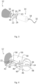
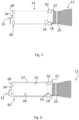
- the inflator device 14 is preferably in the form of a cylindrical gas cartridge having a connecting end 16 designed to be connected to the inflatable member 12.
- the connecting end 16 is preferably inserted and blocked in a gas tightly manner into an opening 18 of the inflatable member 12.
- the connecting end 16 of the gas cartridge 14 can be clamped inside the opening 18 by means of a holding ring 20 (see for example figures 5 and 6 ).
- the connecting end 16 of the gas cartridge 14 can be inserted inside a corresponding cap 22 fastened at the opening 18 of the inflatable member 12 (see for example figures 3 and 4 ).
- the connecting end 16 of the gas cartridge 14 can be inserted by pressure into the cap 22.
- the connecting end 16 of the gas cartridge 14 can be provided with an external thread 24 suitable for being screwed into a corresponding internal thread 26 provided inside the cap 22.
- the inflator device 14 can be triggered by means of an electronic or mechanical mechanism.
- the wearable protection device 10 comprises at least one sensor 28 designed to detect forces acting on the wearable protection device 10.
- two sensors 28 are, for example, applied at the shoulder portion of the wearable protection device 10.
- one or more sensors 28 are applied, for example, in a housing 29 positioned at the upper back portion of the wearable protection device 10.
- the housing 29 is shown in detail in figures 7 and 8 .
- at least one sensor can be directly applied on the wearable protection device and at least one sensor can be positioned inside a protection applied on the wearable protection device.
- the wearable protection device 10 comprises at least one accelerometer, designed to detect the accelerations acting on the wearable protection device, and/or at least one gyroscope, designed to detect movements and orientation of the wearable protection device.
- the wearable protection device 10 can further comprise a control unit 30 designed to process the data detected by the sensor 28 and to send a triggering signal to the inflator device 14, when a crash situation is identified.
- a "crash situation” should be intended a situation wherein the wearable protective device undergoes a sudden acceleration/deceleration and/or a sudden variation in its orientation and in its angular velocity.
- a sudden acceleration or deceleration undergone by the wearable protection device can identify that the motorcycle has hit an obstacle or that the wearer has lost the control of the motorcycle being thrown from the saddle.
- the control unit 30 is preferably housed in a protected zone of the wearable protection device 10, like for example a back protector 31 applied to the wearable protection device (see for example figure 1 ) or the housing 29 also used for housing the sensor 28 and the gas cartridge 14.
- the control unit 30 is designed to process at regular time intervals (for example 1ms) the data received from the sensor 28 so as to obtain an information about the forces acting on the wearable protection device 10.
- control unit 30 If the control unit 30 detects, on the basis of an algorithm implemented therein, that a crash situation is occurring, a triggering signal is sent from the control unit 30 to the inflator device 14 so that the inflatable member 12 can be inflated.
- the inflator device 14 can be triggered by using an activation cable or tether connecting the wearable protection device to the motorcycle.
- the activation cable has a first end connected to the motorcycle and a second end fixed to a triggering device, designed to trigger a firing pin, which in turn is configured to activate the inflator device.
- the wearable protection device 10 comprises a safety device 40 designed to signal an unsafe state of the wearable protection device 10 if the inflator device 14 is decoupled or not properly coupled to the inflatable member 12.
- the inflator device 14 is not properly connected to the inflatable member 12 if the connection is not gas tight. Such an occurrence can happen, for example, if the connecting end 16 of the inflator device 14 is spaced apart from the corresponding receiving opening/seat 18 provided in the inflatable member 12.
- the safety device 40 is able to provide the wearer with a direct visual information, since the wearer will see that the gas cartridge 14 is at least partially spaced apart from the holding seat 46 or not inserted therein.
- Such a safety device 40 can be used both in wearable protection device 10 electronically activated and in wearable protection device mechanically activated.
- the gas cartridge cannot be inserted inside the holding seat 46 since the rear portion of the gas cartridge 14 will hit the rear abutment surface 48 or the front and rear abutment surfaces 48, 50 will not be able to match the reference notches 54.
- the wearer has thus an immediate feedback about the mutual positioning between the gas cartridge 14 and the inflatable member 12 and he is induced to act on the gas cartridge 14 so as to properly connect it to the inflatable member 12.
- a safety sensor connected to the control unit 30, can be applied on an inner surface of the holding seat 46, namely on a surface which is designed to be in contact with the inflator device 14 when the inflator device is inserted in the holding seat 46.
- the safety sensor can be a mechanical switch or a pressure sensor.
- the wearable protection device can comprise two holding seats 46 each designed for housing one inflator device 14; said holding seats 46 being both provided with a safety sensor connected to the control unit 30 on their inner surface.
- control unit 30 will be switched off or will be kept switched off if one of the inflator devices is not properly inserted inside its holding seat.
- the holding seat 46 can comprise a cover 56 suitable for protecting the gas cartridge 14 (see figures 4 , 7 and 8 ).
- the cover 56 can be provided with first fastening means 58 designed to be coupled with corresponding second fastening means 60 of the holding seat 46 so as to permit the fastening of the cover 56 to the holding seat 46.
- First and second fastening means 58, 60 are designed to be matched to each other only if the safety device 40 permits the insertion of the inflator device 14 inside the holding seat 46.
- the wearable protection device is in an unsafe state being the cover 56 spaced apart from the holding seat 46.
- the safety device 40 can be designed to switch off the control unit 30 or to keep the control unit 30 switched off if the wearable protection device is in an unsafe state.
- the safety device 40 can comprise a safety or contact sensor 42, connected to the control unit 30, which can be positioned on a top edge of the holding seat 46 or on a bottom edge of the cover 56 (see figure 4 ).
- a safety or contact sensor 42 is designed to switch on the control unit 30 once the cover 56 is properly fixed to the holding seat 46 and to switch off or to keep the control unit switched off when the cover 56 is removed from the seat.
- a not properly fastening of the cover 56 to the holding seat 46 signals an unsafe state of the wearable protection device since the inflator device 14 is not properly coupled to the inflatable member 12.
- the safety device 40 in case the gas cartridge 14 must be replaced, is able to re-activate the control unit 30 only if the gas cartridge 14 is correctly positioned inside its holding seat 46 and/or the cover 56 is properly fastened to the holding seat 46.
- the wearable protection device 10 can be provided with two holding seats 46, each seat being suitable for housing a corresponding gas cartridge 14. These holding seats 46 can be arranged on a supporting plate 62, suitable for being fixed to the outer surface of the wearable protection device 10.
- Both seats can be provided with the above mentioned safety device 40 and with a corresponding cover 56.
- both safety devices 40 comprise a contact sensor 42 positioned on the cover 56 or on the seat 46
- the control unit 30 will be switched off or it will be kept switched off, if one of the gas cartridges 14 is not properly inserted inside its holding seat 46, so as not to permit the correct positioning of the cover over the holding seat.
- the supporting plate 62 can have a single cover 56 suitable for covering both holding seats 46.
- a contact sensor 42 can be applied at the bottom rim of the cover 56 or at a top surface of the supporting plate 62.
- the cover 56 can be properly fixed to the supporting plate 62, only if both gas cartridges are properly inserted inside their holding seats 46.
- a proper connection between cover and supporting plate causes the pressing of the contact sensor 42 which emits a corresponding signal to the control unit.
- the safety device allows a safe and proper replacement of the gas cartridge without needing to return the wearable protection device to a customer service.
- the safety device offers a reliable feedback about the connection between the gas cartridge and the inflatable member, so that also a final user not having a specific training is able to understand whether the gas cartridge, used in replacement of an exhausted gas cartridge, has been properly connected to the inflatable member.
- the safety device offers a protection against possible hazards occurring during the replacement of the gas cartridge since it is able to switch off or to keep in a switched off status the control unit until the gas cartridge is not connected or not properly connected to the inflatable member, so as to avoid that the pyrotechnic charge of the gas cartridge can be inadvertently activated.
Landscapes
- Textile Engineering (AREA)
- Health & Medical Sciences (AREA)
- Engineering & Computer Science (AREA)
- General Health & Medical Sciences (AREA)
- Physical Education & Sports Medicine (AREA)
- General Physics & Mathematics (AREA)
- Physics & Mathematics (AREA)
- Business, Economics & Management (AREA)
- Emergency Management (AREA)
- Heart & Thoracic Surgery (AREA)
- Chemical & Material Sciences (AREA)
- Analytical Chemistry (AREA)
- Professional, Industrial, Or Sporting Protective Garments (AREA)
- Emergency Lowering Means (AREA)
Applications Claiming Priority (3)
| Application Number | Priority Date | Filing Date | Title |
|---|---|---|---|
| IT102019000020298A IT201900020298A1 (it) | 2019-11-04 | 2019-11-04 | Dispositivo di protezione indossabile |
| PCT/EP2020/080569 WO2021089439A1 (en) | 2019-11-04 | 2020-10-30 | Wearable protection device |
| EP20796849.6A EP4054366B1 (de) | 2019-11-04 | 2020-10-30 | Am körper tragbare schutzvorrichtung |
Related Parent Applications (1)
| Application Number | Title | Priority Date | Filing Date |
|---|---|---|---|
| EP20796849.6A Division EP4054366B1 (de) | 2019-11-04 | 2020-10-30 | Am körper tragbare schutzvorrichtung |
Publications (1)
| Publication Number | Publication Date |
|---|---|
| EP4529794A1 true EP4529794A1 (de) | 2025-04-02 |
Family
ID=69701452
Family Applications (2)
| Application Number | Title | Priority Date | Filing Date |
|---|---|---|---|
| EP24210728.2A Withdrawn EP4529794A1 (de) | 2019-11-04 | 2020-10-30 | Tragbare schutzvorrichtung |
| EP20796849.6A Active EP4054366B1 (de) | 2019-11-04 | 2020-10-30 | Am körper tragbare schutzvorrichtung |
Family Applications After (1)
| Application Number | Title | Priority Date | Filing Date |
|---|---|---|---|
| EP20796849.6A Active EP4054366B1 (de) | 2019-11-04 | 2020-10-30 | Am körper tragbare schutzvorrichtung |
Country Status (8)
| Country | Link |
|---|---|
| US (1) | US12108816B2 (de) |
| EP (2) | EP4529794A1 (de) |
| JP (2) | JP7849291B2 (de) |
| KR (1) | KR102843907B1 (de) |
| CN (1) | CN114980765A (de) |
| ES (1) | ES3006907T3 (de) |
| IT (1) | IT201900020298A1 (de) |
| WO (1) | WO2021089439A1 (de) |
Families Citing this family (8)
| Publication number | Priority date | Publication date | Assignee | Title |
|---|---|---|---|---|
| FR3103085B1 (fr) * | 2019-11-15 | 2022-03-25 | Livbag Sas | Dispositif d'interface d'un dispositif de sécurité gonflable individuel |
| IT202100021860A1 (it) * | 2021-08-13 | 2023-02-13 | Dainese Spa | Dispositivo di gonfiaggio |
| US12162738B2 (en) * | 2021-10-28 | 2024-12-10 | Toyota Research Institute, Inc. | Robots and sensor systems having compliant members |
| EP4193861A1 (de) * | 2021-12-13 | 2023-06-14 | Dainese S.p.A. | Ausgestattete kleidung |
| EP4197390B8 (de) | 2021-12-20 | 2025-07-16 | Autoliv Development AB | Tragbares sicherheitssystem und tasche mit einem solchen tragbaren sicherheitssystem |
| IT202200017448A1 (it) | 2022-08-22 | 2024-02-22 | Dainese Spa | Dispositivo di protezione indossabile |
| IT202200018723A1 (it) | 2022-09-13 | 2024-03-13 | Alpinestars Res Spa | Dispositivo di protezione indossabile comprendente un elemento gonfiabile e metodo per attivare in sicurezza l'elemento gonfiabile di detto dispositivo di protezione indossabile |
| IT202300005097A1 (it) | 2023-03-17 | 2024-09-17 | D Air Lab S R L | Dispositivo di gonfiaggio |
Citations (4)
| Publication number | Priority date | Publication date | Assignee | Title |
|---|---|---|---|---|
| US4161797A (en) * | 1976-03-15 | 1979-07-24 | Ruscigno Harry G | Detonator assembly |
| US20030182040A1 (en) * | 2000-09-04 | 2003-09-25 | Davidson Maximilian E | Self triggering impact protection system |
| US20170224031A1 (en) * | 2011-02-03 | 2017-08-10 | Hip Hope Technologies Ltd. | Hip protector system and method for hip fracture prevention |
| US20190223525A1 (en) * | 2016-07-01 | 2019-07-25 | Alpinestars Research Srl | Garmet provided with an inflatable protective device |
Family Cites Families (21)
| Publication number | Priority date | Publication date | Assignee | Title |
|---|---|---|---|---|
| JP2004105620A (ja) * | 2002-09-20 | 2004-04-08 | Kazuo Shimizu | ガス発生装置用ケースとガス発生装置 |
| JP4548729B2 (ja) * | 2005-09-21 | 2010-09-22 | 本田技研工業株式会社 | 着用式エアバッグ装置 |
| US8419058B2 (en) * | 2008-03-21 | 2013-04-16 | Trw Vehicle Safety Systems Inc. | Dual volume air bag |
| JP5421166B2 (ja) * | 2010-03-24 | 2014-02-19 | 本田技研工業株式会社 | エアバッグジャケット作動システム |
| US8400308B2 (en) * | 2010-04-30 | 2013-03-19 | Oleg Aronov | System and method for identifying object and releasing its security |
| ITTV20120084A1 (it) * | 2012-05-15 | 2013-11-16 | Alpinestars Res Srl | Dispositivo di protezione autonomo ed indossabile e complesso di abbigliamento protettivo |
| ITTV20120124A1 (it) * | 2012-06-26 | 2013-12-27 | Alpinestars Res Srl | Dispositivo di protezione gonfiabile montato su fodera e assieme d'abbigliamento protettivo |
| US9563244B2 (en) * | 2013-01-08 | 2017-02-07 | Hzo, Inc. | Apparatuses, systems, and methods for reducing power to ports of electronic devices |
| BR112015020103B1 (pt) * | 2013-02-21 | 2021-11-16 | Andras Fenyves | Sistema de proteção contra acidente |
| TW201521615A (zh) * | 2014-06-10 | 2015-06-16 | Cheng-Mao Lee | 充氣式防護衣 |
| WO2016012359A1 (en) * | 2014-07-22 | 2016-01-28 | Alpinestars Research Srl | "protective garment provided with an inflatable protective device and associated inflating method" |
| FR3031908B1 (fr) * | 2015-01-28 | 2018-07-27 | In&Motion | Dispositif de detection de la perte d'un ski |
| US9928386B1 (en) * | 2015-06-08 | 2018-03-27 | Amazon Technologies, Inc. | Data protection system |
| CN105004495B (zh) * | 2015-07-02 | 2017-07-18 | 高田(长兴)汽车安全装置有限公司 | 气体发生器出气口铝箔贴附密封性检测装置及其检测方法 |
| KR102586012B1 (ko) * | 2016-01-27 | 2023-10-10 | 삼성전자주식회사 | 청소기 및 그 제어 방법 |
| US11253013B2 (en) * | 2016-02-29 | 2022-02-22 | Active Protective Technologies, Inc. | Airbag actuator mounted in a custom buckle for personal impact protection systems |
| US10102768B2 (en) * | 2016-03-19 | 2018-10-16 | Fujitsu Limited | Behavior variability and complexity modeling using a construction toy |
| GB201707645D0 (en) * | 2017-05-12 | 2017-06-28 | Playfinity As | Electronic sensing devices |
| CN110081236B (zh) * | 2019-05-10 | 2024-05-28 | 成都霍姆赛福科技有限公司 | 一种燃气安全阀、燃气安全检测报警系统及方法 |
| SE543986C2 (en) * | 2019-01-17 | 2021-10-19 | Hoevding Sverige Ab | Airbag system comprising control unit arranged to control inflation of the airbag based on a measured magnetic field |
| US20210058105A1 (en) * | 2019-08-19 | 2021-02-25 | Jonathan Philip Landry | Privacy apparatus for electronics and related methods |
-
2019
- 2019-11-04 IT IT102019000020298A patent/IT201900020298A1/it unknown
-
2020
- 2020-10-30 ES ES20796849T patent/ES3006907T3/es active Active
- 2020-10-30 EP EP24210728.2A patent/EP4529794A1/de not_active Withdrawn
- 2020-10-30 WO PCT/EP2020/080569 patent/WO2021089439A1/en not_active Ceased
- 2020-10-30 EP EP20796849.6A patent/EP4054366B1/de active Active
- 2020-10-30 US US17/773,515 patent/US12108816B2/en active Active
- 2020-10-30 KR KR1020227018552A patent/KR102843907B1/ko active Active
- 2020-10-30 CN CN202080090195.7A patent/CN114980765A/zh active Pending
- 2020-10-30 JP JP2022525970A patent/JP7849291B2/ja active Active
-
2024
- 2024-12-06 JP JP2024213845A patent/JP2025026588A/ja not_active Withdrawn
Patent Citations (4)
| Publication number | Priority date | Publication date | Assignee | Title |
|---|---|---|---|---|
| US4161797A (en) * | 1976-03-15 | 1979-07-24 | Ruscigno Harry G | Detonator assembly |
| US20030182040A1 (en) * | 2000-09-04 | 2003-09-25 | Davidson Maximilian E | Self triggering impact protection system |
| US20170224031A1 (en) * | 2011-02-03 | 2017-08-10 | Hip Hope Technologies Ltd. | Hip protector system and method for hip fracture prevention |
| US20190223525A1 (en) * | 2016-07-01 | 2019-07-25 | Alpinestars Research Srl | Garmet provided with an inflatable protective device |
Also Published As
| Publication number | Publication date |
|---|---|
| KR102843907B1 (ko) | 2025-08-08 |
| EP4054366C0 (de) | 2024-11-27 |
| US12108816B2 (en) | 2024-10-08 |
| JP2025026588A (ja) | 2025-02-21 |
| EP4054366B1 (de) | 2024-11-27 |
| US20220361599A1 (en) | 2022-11-17 |
| EP4054366A1 (de) | 2022-09-14 |
| IT201900020298A1 (it) | 2021-05-04 |
| JP2023502884A (ja) | 2023-01-26 |
| ES3006907T3 (en) | 2025-03-19 |
| WO2021089439A1 (en) | 2021-05-14 |
| CN114980765A (zh) | 2022-08-30 |
| JP7849291B2 (ja) | 2026-04-21 |
| KR20220108065A (ko) | 2022-08-02 |
Similar Documents
| Publication | Publication Date | Title |
|---|---|---|
| EP4054366B1 (de) | Am körper tragbare schutzvorrichtung | |
| EP2863767B1 (de) | Auskleidungsmontierte aufblasbare schutzeinrichtung und schutzbekleidungsanordnung | |
| US10046726B2 (en) | Airbag safety system for a two-wheeled vehicle | |
| US6139050A (en) | Safety device for motorcyclists | |
| EP4178392B1 (de) | Tragbare schutzvorrichtung | |
| KR20210136080A (ko) | 임박한 충격으로부터 사용자의 두개골 및 경부 영역을 보호하기 위한 보호 장치 | |
| US12486009B2 (en) | Interface device for an inflatable individual safety device | |
| EP3326476B1 (de) | An einen helm anpassbarer airbag | |
| WO2016132255A1 (en) | Inflatable protection system | |
| US20220273067A1 (en) | Emergency protective helmet | |
| EP3237272B1 (de) | Aufpumpbarer schutz für einen kindersitz | |
| EP4054367B1 (de) | Am körper tragbare schutzvorrichtung | |
| US20260083186A1 (en) | Wearable protection device comprising an inflatable member and method for safely activating the inflatable member of said wearable protection device | |
| KR20220086199A (ko) | 오토바이 보호구 | |
| KR101305700B1 (ko) | 차량용 운전석 에어백장치 및 구동방법 | |
| KR20200061461A (ko) | 인플레이터를 구비한 안전 디바이스 |
Legal Events
| Date | Code | Title | Description |
|---|---|---|---|
| PUAI | Public reference made under article 153(3) epc to a published international application that has entered the european phase |
Free format text: ORIGINAL CODE: 0009012 |
|
| STAA | Information on the status of an ep patent application or granted ep patent |
Free format text: STATUS: THE APPLICATION HAS BEEN PUBLISHED |
|
| AC | Divisional application: reference to earlier application |
Ref document number: 4054366 Country of ref document: EP Kind code of ref document: P |
|
| AK | Designated contracting states |
Kind code of ref document: A1 Designated state(s): AL AT BE BG CH CY CZ DE DK EE ES FI FR GB GR HR HU IE IS IT LI LT LU LV MC MK MT NL NO PL PT RO RS SE SI SK SM TR |
|
| STAA | Information on the status of an ep patent application or granted ep patent |
Free format text: STATUS: THE APPLICATION IS DEEMED TO BE WITHDRAWN |
|
| 18D | Application deemed to be withdrawn |
Effective date: 20251003 |