EP4529812A1 - Verfahren zur herstellung eines getränks wie kaffee und getränkebrühmaschine zur herstellung eines getränks - Google Patents
Verfahren zur herstellung eines getränks wie kaffee und getränkebrühmaschine zur herstellung eines getränks Download PDFInfo
- Publication number
- EP4529812A1 EP4529812A1 EP23200145.3A EP23200145A EP4529812A1 EP 4529812 A1 EP4529812 A1 EP 4529812A1 EP 23200145 A EP23200145 A EP 23200145A EP 4529812 A1 EP4529812 A1 EP 4529812A1
- Authority
- EP
- European Patent Office
- Prior art keywords
- pump
- brewing chamber
- liquid
- ingredient
- seconds
- Prior art date
- Legal status (The legal status is an assumption and is not a legal conclusion. Google has not performed a legal analysis and makes no representation as to the accuracy of the status listed.)
- Withdrawn
Links
Images
Classifications
-
- A—HUMAN NECESSITIES
- A47—FURNITURE; DOMESTIC ARTICLES OR APPLIANCES; COFFEE MILLS; SPICE MILLS; SUCTION CLEANERS IN GENERAL
- A47J—KITCHEN EQUIPMENT; COFFEE MILLS; SPICE MILLS; APPARATUS FOR MAKING BEVERAGES
- A47J31/00—Apparatus for making beverages
- A47J31/002—Apparatus for making beverages following a specific operational sequence, e.g. for improving the taste of the extraction product
-
- A—HUMAN NECESSITIES
- A47—FURNITURE; DOMESTIC ARTICLES OR APPLIANCES; COFFEE MILLS; SPICE MILLS; SUCTION CLEANERS IN GENERAL
- A47J—KITCHEN EQUIPMENT; COFFEE MILLS; SPICE MILLS; APPARATUS FOR MAKING BEVERAGES
- A47J31/00—Apparatus for making beverages
- A47J31/24—Coffee-making apparatus in which hot water is passed through the filter under pressure, i.e. in which the coffee grounds are extracted under pressure
- A47J31/34—Coffee-making apparatus in which hot water is passed through the filter under pressure, i.e. in which the coffee grounds are extracted under pressure with hot water under liquid pressure
- A47J31/36—Coffee-making apparatus in which hot water is passed through the filter under pressure, i.e. in which the coffee grounds are extracted under pressure with hot water under liquid pressure with mechanical pressure-producing means
-
- A—HUMAN NECESSITIES
- A47—FURNITURE; DOMESTIC ARTICLES OR APPLIANCES; COFFEE MILLS; SPICE MILLS; SUCTION CLEANERS IN GENERAL
- A47J—KITCHEN EQUIPMENT; COFFEE MILLS; SPICE MILLS; APPARATUS FOR MAKING BEVERAGES
- A47J31/00—Apparatus for making beverages
- A47J31/44—Parts or details or accessories of beverage-making apparatus
- A47J31/52—Alarm-clock-controlled mechanisms for coffee- or tea-making apparatus ; Timers for coffee- or tea-making apparatus; Electronic control devices for coffee- or tea-making apparatus
Definitions
- the present invention relates to a method for preparing a beverage such as coffee from an ingredient such as ground coffee using a coffee making machine comprising a brewing chamber having an inlet and an outlet, a pump and a fluid connection extending between the pump and the inlet, the method comprising filling the brewing chamber with the ingredient, prewetting the ingredient, opening the outlet of the brewing chamber (e.g. under the influence of fluid pressure inside the brewing chamber) if the outlet of the brewing chamber is closed, and letting flow a liquid such as water through the brewing chamber for brewing the beverage.
- a coffee making machine comprising a brewing chamber having an inlet and an outlet, a pump and a fluid connection extending between the pump and the inlet, the method comprising filling the brewing chamber with the ingredient, prewetting the ingredient, opening the outlet of the brewing chamber (e.g. under the influence of fluid pressure inside the brewing chamber) if the outlet of the brewing chamber is closed, and letting flow a liquid such as water through the brewing chamber
- the invention also relates to a beverage brewing machine for preparing a beverage such as coffee from an ingredient such as ground coffee, the machine comprising a brewing chamber having an inlet and an outlet, a pump, a fluid connection extending between the pump and the inlet and a control circuitry for controlling the pump, wherein the machine is arranged for, in use, receiving or loading the ingredient into the brewing chamber such that the ingredient is positioned in a fluid path extending in the brewing chamber from the inlet to the outlet; wherein the machine is further arranged for prewetting the ingredient, opening the outlet of the brewing chamber (e.g. under the influence of fluid pressure inside the brewing chamber) if the outlet is closed, and letting flow a liquid such as water through the brewing chamber for brewing the beverage.
- a beverage brewing machine for preparing a beverage such as coffee from an ingredient such as ground coffee
- the machine comprising a brewing chamber having an inlet and an outlet, a pump, a fluid connection extending between the pump and the inlet and a
- Such a method is known in relation to a fluid coffee machine from EP2001343B1 .
- a standard and non-expensive pump is used.
- the pump is used for prewetting the ingredient in the capsule by means of a pressurised liquid.
- the pump is further used for keeping the capsule pressurised (blooming phase of the prewetting), for opening an outlet side of the capsule by means of a pressurised liquid, and for brewing a beverage by means of an increased pressurised liquid.
- These different phases require different fluid pressures respectively. If the fluid pressure would be too high during prewetting there is a risk that the outlet side of the capsule or brewing chamber is opened too early, in case where the capsule, respectively brewing chamber is of a type that is closed at its outlet side.
- the brewing process starts and the prewetting phase will be early terminated. If the fluid pressure during the prewetting phase is too low, prewetting may not have been sufficient on the moment in time that brewing is started.
- a similar problem may occur with capsules, respectively brewing chambers that are open at their outlet from the start, for example in case where a brewing chamber outlet is formed by or comprises a septum with a small orifice or a duckbill valve, or in case where a capsule outlet is covered with filtering paper or perforated foil. In such cases, prewetting may not have been sufficient on the moment in time that liquid starts flowing out of the capsule or brewing chamber. During prewetting the interaction between the liquid and the ingredient may not result in optimal prewetting of the ingredient itself.
- the object of the invention is to improve the known method and machine on at least one aspect.
- the method according to the invention is characterized in that the pump is of a type which, in use, is operated by an AC-voltage wherein each cycle of the AC voltage causes the pump to make one pump cycle (hereinafter also referred to as stroke) wherein a predetermined amount of liquid is released by the pump, the AC-voltage having a cycle time T, the method comprising in succession comprising the following steps:
- the object of step (b) is to make the ingredient in the brewing chamber wet and the object of steps (c)-(e) (also referred to as blooming phase of the prewetting phase) is to keep the ingredient wet at a desired fluid pressure.
- the desired accurate pressure control (specifically in the prewetting phase during steps (c)-(e)) can be realised. Specifically due to the selected values for ts and tr a balance between pressurised flow and interruption is obtained which contributes to a desired prewetting and blooming.
- the steps (c)-(e) i.e. the blooming phase
- the ingredient is wet and pressure is maintained around a desired level in the brewing chamber.
- the object of step (c) is to keep the ingredient wet and at rest with a certain fluid pressure during a certain desired length of time. The pressure may however slowly decrease during this step (c).
- the object of step (d) is to slightly increase the pressure in the brewing chamber and maintain or bring back the pressure in the brewing chamber at a desired level. Because N is larger than 1 a prewetting phase with slightly varying pressure in the brewing chamber is obtained which also contributes to a desired prewetting.
- a desired type of prewetting is not only a surrounding of an ingredient particle such as ground coffee by liquid but also an absorption of the liquid into such an ingredient particle.
- a desired type of prewetting is also an interaction of the liquid with the majority of the ingredients in the brewing chamber, preferably more than 50%, more preferably more than 70%. If there is a large penetration depth of the liquid into the brewing chamber towards its outlet side this may come with the risk that -if the brewing chamber's outlet is closed- the outlet may become opened due to relatively high fluid forces acting on the outlet. If there is a large penetration depth of the liquid into the brewing chamber towards its outlet side this may come with the risk that -if the brewing chamber's outlet is open - an undesired amount of liquid may flow from the brew chamber's outlet during the prewetting phase. Due to a value of tr being smaller than ts the early opening of the outlet can be avoided. Due to a value of N > 1 a sufficient penetration depth of the liquid towards the outlet side can be obtained.
- n1, n2 and N are selected such that during prewetting in steps (b)-(e) no liquid flows from the brewing chamber via its outlet given the value of T and the amount of liquid which is released during one stroke of the pump.
- ts lays in a time-interval of 0.75-0.85 seconds.
- the advantage is that the forces acting on the outlet can remain sufficiently small to avoid early opening of the brewing chamber.
- tr 0.01-0.04 seconds.
- T 0.02 seconds or 0.0167 seconds.
- the latter are values which can practically be derived from existing grids (such as in the EU or US).
- n1 20-45, more preferably 30-44, more preferably 35-40 such as 30, 35 or 40.
- n2 1-4, preferably 1.
- n1 may have one and the same value in each of the carried out steps (c) and/or n2 may have one and the same value in each of the carried out steps (d).
- steps (c) of the carried out steps (c) n1 may have different values respectively and/or in at least two steps (d) of the carried out steps (d) n2 may have different values respectively.
- step (b) a predetermined amount of liquid is pumped towards and into the brewing chamber. This amount is sufficient for pre-wetting the ingredient in the brewing chamber. It is sufficient for building up a required pressure at the inlet of the brewing chamber. At the same time it is avoided that the brewing chamber's outlet is opened under the influence of liquid pressure or -in case the brewing chamber has an outlet that is open from the start- that liquid flows out of said open outlet during prewetting, especially during the blooming phase.
- the pump is activated for a time ti, wherein ti lays in the range of 1-15 seconds, preferably 2-4 seconds.
- the time ti is sufficient for building up a required pressure at the inlet of the brewing chamber for subsequently starting step (c).
- the pump may for instance make 50-750, more specifically 400-200 strokes.
- the pump pumps 0.01-0.15 ml, more preferably 0.07 ml liquid.
- the inner volume of the brewing chamber (this is the volume which may be filled with the ingredient and the liquid) may be in the range of 10-40 ml.
- step (f) 15-400 ml, preferably 20-250 ml, more preferably 20-120 ml beverage may be brewed.
- N may lay in the range of 1-80, preferably 1-30, more preferably in the range of 5-15.
- Steps (c)-(e) may take 3-35 seconds, preferably 6-20 seconds, more preferably 8-12 seconds. This proofs to be a length of time to allow an effective prewetting of the ingredient.
- the fluid pressure at the inlet side of the brewing chamber may be 0.5-8 bar, preferably 2,5-5 bar. This proofs an effective pressure to be used in the prewetting phase.
- step (f) the pressure raises relative to the pressure at the inlet side of the brewing chamber during steps (c)-(e), preferably to 4-12 bar, more preferably to 5-7 bar.
- the pump is operated uninterrupted. This means that during step (f) it operates preferably at full power.
- the pump may be at least one time interrupted.
- the machine according to the invention is characterized in that the pump is of a type which, in use, is operated by an AC-voltage generated by the control circuitry wherein each cycle of the AC voltage causes the pump to make one stroke wherein a predetermined amount of liquid is released by the pump, the AC-voltage having a cycle time T, the control circuitry being arranged such that in use the pump is controlled by the AC voltage as follows:
- a desired prewetting can be performed by the machine with a reduced risk that the outlet is opened early for the same reasons as discussed above for the method.
- the machine can however also be used for prewetting the ingredient in a brewing chamber from which the outlet is already open before the ingredient is received or loaded into the brewing chamber.
- the desired type of prewetting as discussed above for example penetration depth and/or absorption of liquid into the ingredient
- control circuitry may be arranged such that, in use, in step (b) the pump is operated continuously or wherein in step (b) the pump is at least one time interrupted.
- control circuitry may be arranged such that, in use, in each of the carried out steps (c) n1 has one and the same value and/or wherein in each of the carried out steps (d) n2 has one and the same value.
- control circuitry may be arranged such that, in use, in at least two steps (c) of the carried out steps (c) n1 has different values respectively and/or wherein in at least two steps (d) of the carried out steps (d) n2 has different values respectively.
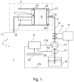
- a system is provided with reference number 1.
- the system is provided with a beverage brewing machine 2 for preparing a beverage from a brewing chamber 8 filled with an ingredient such as ground coffee 6.
- the brewing chamber 8 has an inlet 10 and an outlet 12.
- a spout 13 is provided for collecting a beverage flowing through the outlet 12.
- the machine 2 further comprises a pump 14 and a fluid connection 16 extending between an outlet side of the pump and the inlet 10.
- the machine comprises in this example a reservoir 18 which can be filled with water and a further fluid connection 20 extending between the reservoir 18 and an inlet side of the pump 14.
- Heating means 17 are provided for heating a liquid flowing through the fluid connection 16.
- the machine is further provided with a control circuitry 21 for controlling the pump 14.
- the machine comprises in this example a control-panel 22 for providing instructions to the control circuitry 21 by a user.
- the pump 14 is of a type which, in use, is operated by an AC-voltage signal generated by the control circuitry 21 wherein each cycle of the AC voltage signal causes the pump to make one stroke wherein a predetermined amount of liquid is released by the pump.
- the pump 14 may for example be a well-known positive displacement pump.
- the pump which may be used is of a type also known by the name vibration pump, vibe pump and solenoid pump.
- the brewing chamber 8 comprises a cylinder 23 for receiving the ingredient 6 and a closing piston 24 for closing an open end of the cylinder 23.
- the other end of the cylinder 23 may be provided with a second piston 25 that may serve as ejection piston, to automatically eject the used ingredient 6 from the cylinder 23 at the end of a brewing cycle, in a known manner.
- the cylinder 23 may be embodied as a portafilter, which at the end of each brewing cycle can be manually removed from the machine 2 for emptying.
- Appropriate sealing means 26 may be provided between the respective pistons 24, 25 and the cylinder 23.
- the outlet 12 is provided in the closing piston 24 and the inlet 10 is provided in the opposite end of the cylinder 23.
- the location of the inlet 10 and outlet 12 may be reversed, that is, the inlet 10 may be provided in the closing piston 24 and the outlet 12 may be provided in the cylinder 23.
- the closing piston 24 preferably is provided with a liquid distribution head, to allow even distribution of the liquid over the ingredient 6.
- the inlet 10 and/or the outlet 12 may be covered by a filter (shown in dashed lines in figure 1 ), to prevent ingredient 6 from exiting the cylinder 23 via inlet 10 or outlet 12.
- the position of the closing piston 24 may be varied so that the inner volume of the brewing chamber 8 (this is the volume which may be filled with the ingredient 6 and the liquid) may be varied to accommodate for different amounts of ingredient 6.
- the inner volume of the brewing chamber may for instance be varied in the range of 10-40 ml.
- the cylinder 23 can be moved from a position below a grinder outlet (not shown) for receiving ground coffee, to a position below the closing piston 24 (away from the grinder outlet). Subsequently the cylinder 23, the closing piston 24, or both can be moved towards each other to close the brewing chamber 8.
- the opening and closing of the brewing chamber 8 may be performed manually, for example by means of a lever. Alternatively opening and closing of the brewing chamber may be carried out by means of an electromotor or a hydraulic actuator, controlled by the control circuitry 21.
- the cylinder 23 may be a portafilter that can be manually removed from the machine after each brewing cycle, in order to remove the used coffee puck. Once emptied, the portafilter can be filled with fresh coffee grounds and manually re-installed into the machine. Alternatively, if the machine includes an integrated grinder, the empty portafilter may be re-installed in the machine, where it then can be loaded with fresh coffee grounds from the grinder.
- the working of the machine for preparing a beverage is as follows.
- step (a) the ingredient 6 is loaded into the brewing chamber 8 in any of the ways described above, such that the ingredient 6 is positioned in a fluid path extending in the brewing chamber 8 from the inlet 10 to the outlet 12.
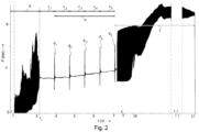
- control circuitry 21 controls pump 14 via control line 21a by means of the AC voltage as follows: In a step (b) by means of the pump 14 liquid, more specifically water under pressure is fed from the reservoir 18 via the fluid connections 20 and 16 and the inlet 10 towards and into the brewing chamber 8. As a result of the action of the pump 14 the water pressure at point P in figure 1 will change as is shown in figure 2 . Also, the control circuitry 21 may control the heating means 17 via control line 21b so that the water flowing through the fluid connection 16 is heated to a desired temperature, for example 90 degrees Celsius. Other values are possible. It is also possible to not heat the water, e.g. by leaving the heater 17 inactivated.
- a value of fluid pressure downstream of the pump 14 is the fluid pressure which can be measured outside the brewing chamber close to the inlet 10 thereof and therefore close to the interior of the brewing chamber 8.
- such pressure values are defined at position P. It is assumed that this is the pressure at the inlet 10 of the brewing chamber.
- a step (e) a combination of first step (c 1 ) and subsequent step (di) is repeated for N times wherein N is an integer larger than 1.
- N an integer larger than 1.
- N 4 so that all steps (c i ) and (d i ) take 5*0.84 seconds. This makes 4.2 seconds.
- step (f) after step (e) the operation of the pump 14 is continued by submitting the uninterrupted AC voltage signal to the pump.
- the pump 14 operates at full power within the machine.
- the fluid pressure in the brewing chamber will increase.
- a beverage is brewed from the interaction between the liquid and the ingredient 6.
- the brewed beverage flows from the brewing chamber via the outlet 12 and is dispensed from the machine via spout 13.
- Each pulse has as an effect that the pump 14 makes one stroke as discussed above.
- the pump submits 150 times the predetermined amount of water relating to one stroke towards the brewing chamber.
- the predetermined amount of liquid (water in the example) relating to one stroke is in this example 0.07 ml. As a result about 10.5 ml of water is pumped towards and into the brewing chamber and the average pressure at position P increases.
- step (b) the pressure at position P has the character of a pulsating pressure with a certain bandwidth.
- step (b) the ingredient in the brewing chamber has become wet due to the water pumped towards and into the brewing chamber. Because the inner volume of the brewing chamber is in this example about 20 ml, the ingredient becomes wet without liquid flowing from the brewing chamber outlet 12.
- step (d) the pump makes only one stroke.
- the pressure in the brewing chamber slightly decreases and no water is fed into the brewing chamber. Because the pump 14 is in rest the pressure at position P has no longer a pulsating character.
- step (d) the amount of water related to one stroke is submitted towards the brewing chamber with the result that after the first step (d) the pressure is slightly increased again.
- a combination of step (c) and (d) has as a result that the pressure at position P and thereby in the brewing chamber 8 is maintained and water remains in the brewing chamber without the outlet 12 of the brewing chamber being forced open or, if the outlet 12 is of the open type, without water exiting the brewing chamber via the outlet 12, because the water pressure in the brewing chamber remains low enough to prevent this.
- a combination of step (c) and (d) has as a result that the ingredient is prewetted during step (c) and step (d), thus during 0.82 seconds.
- step (d) the pump 14 is interrupted again during a second step (c) indicated with c2. During this period the pressure again slightly decreases. Subsequently after the second step (c) the pump is activated again with one stroke in a second step (d) indicated with d2. Again after the second step (d) the pressure is slightly increased. Again during the combination of second step (c) and second step (d) the ingredient of the brewing chamber is prewetted during 0.82 seconds .
- step (e) the operation of the pump 14 is resumed in step (f) without any interruption for brewing the beverage.
- the pump 14 operates at full power in step (f).
- the pressure at position P and thereby in the brewing chamber 8 will increase. Again the pressure has a pulsating character during step (f).
- the pressure at position P will further increase to a level above 8 bar, for example to 10 bar.
- water flows through the brewing chamber 8 for preparing the beverage.
- the beverage flows via outlet 12 and the spout 13 into a container such as a cup 44.
- step (f) may for instance be around 20 seconds. This means that in this period about 70 ml beverage will be produced (0.07 (ml) * 50 (Hz) *20 (seconds). Due to the prewetting of the ingredient during 4.1 seconds at a pressure level of about 3.5 bar the beverage will have excellent tasting characteristics.
- n1, n2 and N are selected such that during prewetting in steps (c)-(e) the brewing chamber is not opened at its outlet side or at least no water is exiting from the brewing chamber via its outlet 12, given the value of T and the amount of liquid which is pumped by the pump during one stroke. Also during steps (c)-(e) prewetting of the ingredient can take place during a sufficient length of time at a favourable pressure. Other values of the variables discussed above can however be selected.
- T may for example be 0.0167 seconds so that the AC voltage comprises 60 control pulses in one second.
- the value of ts may lay in a time-interval of 0.02-0.9 seconds, preferably 0.4-0.85 seconds, more preferably 0.6-0.8 seconds.
- the value of tr may lay in an interval of 0.01-0.04 seconds.
- T may lay in the range of 0.01-0.04 seconds.
- the value of n2 may lay in the interval of 1-4.
- N may lay in the range of 1-80, preferably 1-30, more preferably in the range of 5-15.
- Steps (c)-(e) may take 3-35 seconds, preferably 6-20 seconds, more preferably 8-12 seconds.
- the pressure at the inlet side of the brewing chamber may be 0.5-8 bar, preferably 2.5-5 bar.
- the pump may be activated for a time ti, wherein ti lays in the range of 1-15 seconds, preferably 2-4 seconds.
- the pump may make 50-750 strokes, preferably 100-200 strokes.
- the fluid pressure may lay in the range of 0.5-8 bar, preferably 2.5-5 bar.
- step (f) the pressure at the inlet side of the brewing chamber may raise relative to the pressure at the inlet side of the brewing chamber during steps (c)-(e), preferably to 4-12 bar, more preferably to 5-7 bar.
- the pump may pump 0.01-0.15 ml liquid.
- step (f) 15-400 ml, preferably 20-250 ml, more preferably 20-120 ml beverage may be brewed.
- the brewing chamber was loaded with ground coffee.
- the ingredient may however also comprise other substances such as tea.
- the machine 2 is provided with a flowmeter 15 for measuring the flowrate of the liquid which is pumped by the pump towards the inlet 10 of the brewing chamber 8.
- the flowmeter is communicatively connected to the control circuitry 21 by means of a control line 15a for submitting, in use, a signal to the control circuitry representing the measured flowrate.
- the flowmeter 15 measures the flowrate of liquid flowing through the further fluid connection 20 upstream of the pump. This equals the flowrate of liquid flowing through the fluid connection 16 towards the inlet 10.
- the flowmeter 15 could have been positioned downstream of the pump 14 to measure the flowrate of liquid flowing through the fluid connection 16.
- the control circuitry 21 may be arranged, in use, to control, the pump based on the information provided by the flowmeter 15 such that in steps (b)-(f) a predetermined amount of liquid is pumped by the pump towards the inlet 10 of the brewing chamber 8 (thus the flowmeter is part of a feedback loop).
- steps (c)-(e) the flow of liquid is purely time controlled without using the information provided by the flowmeter 15 (also referred to as dead reckoning)
- the overall amount of liquid pumped by the pump 14 is measured by the flowmeter and used by the control circuitry 21 to control the total amount of liquid pumped for preparing a beverage.
- control circuitry 21 may be arranged to control the pump 14 in step (b) based on the information provided by the flowmeter 15, such that a predetermined amount of liquid is pumped by the pump towards the inlet of the brewing chamber (again the flowmeter and the control circuitry form a feedback loop).
- the amount of liquid which is used for prewetting may be based on a measurement of the flowmeter 15.
- control circuitry 21 may be arranged for controlling the pump 14 based on the information provided by the flowmeter 15 such that in step (f) a predetermined amount of liquid is pumped by the pump towards the inlet 10 of the brewing chamber 8 (again the flowmeter and the control circuitry form a feedback loop).
- steps (b)-(f) may each be time controlled without the use of a feedback loop wherein the flowmeter 15 may thus be deleted.
- table 1 below the characteristics of steps (c)-(e) with respect to the value of n1 and n2 in the example are summarised.
- the second example may create a higher quantity of coffee crema and also higher solid levels.
- control circuitry 21 is arranged such that, in use, in at least two steps (c) of the carried out steps (c) n1 has different values respectively.
- control circuitry is arranged such that, in use in at least two steps (d) of the carried out steps (d) n2 has different values respectively.
- the third example may be changed such that n1 has the same value in each of the four sequences such that only n2 may have different values in different sequences of steps (c) and (d).
- step (b) the pump 14 may be continuously operated at full power. It is however also possible that the control circuitry 21 is arranged such that, in use, in step (b) the pump is at least one time interrupted. Thus, for example in a first portion of step (b) the pump may be operated continuously and in a following second portion of step (b) the pump is at least one time interrupted. Such variations also fall within the scope of the invention. It is also possible that between step (b) and the first step (c) the pump is operated, optionally with at least one interruption. It is also possible that between step (e) and step (f) the pump is operated, optionally with at least one interruption.
- the brewing chamber 8 is loaded with a fixed amount of ingredient 6.
- the stroke of the closing piston 24 and/or cylinder 23 may be fixed.
- the stroke of the closing piston 24 and/or cylinder 23 may be variable so that the brewing chamber 8 may have a variable internal volume for accommodating varying amounts of ingredient 6.
- the ingredient amounts may for instance be varied depending on a user selected recipe. For example, for larger and/or stronger recipes more ingredient 6 may be loaded into the brewing chamber 8.
- the amount of liquid that is fed through the ingredient in the brewing chamber during steps (b), (d), (e) and/or (f) may be varied accordingly.
- step (b), (c), (d), (e) and/or (f) and/or the time period ti, ts, tr during which operation of the pump is activated, interrupted, respectively resumed again may be varied in dependence of the ingredient amount inside the brewing chamber.
- the other parameters associated with the respective steps (b)-(f), e.g. n1, n2, T, N and/or the fluid pressure at the inlet side of the brewing chamber each of these parameters may be varied in dependence of the ingredient amount that has been loaded into the brewing chamber 8 during step (a).
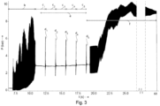
- the pressure time diagram may differ, as can be seen by comparing figure 2 and 3 .
- Figure 3 shows an example of a pressure-time diagram wherein the brewing chamber 8 is loaded with a second amount of ingredient 6 that is larger than the first amount of ingredient, used in the example of figure 2 .
- the second amount of ingredient and the inner volume of the brewing chamber 8 is for example twice as big as that shown in figure 2 , e.g. 40 ml.
- step (b) takes about 12 seconds
- steps (c)-(e) take about 8 seconds (about twice as long as for the first amount of ingredient in figure 2 )
- step (f) takes about 40 seconds.
- n1, n2 and N which determine the prewetting process may be the same as for figure 2 .
- a method and/or machine 2 for preparing a beverage may be provided, wherein the machine comprises a brewing chamber 8 for receiving an amount of ingredient 6, for instance ground coffee (pre-packaged in a capsule or pod, or unpackaged, e.g.
- the beverage brewing machine may for instance be a coffee machine, more specifically a capsule machine, a pod machine, a fully automatic espresso machine with integrated grinder, a manual espresso machine with manually removable portafilter and optionally an integrated grinder, etc.
- prewetting parameters may be varied, such as the duration of the prewetting phase, the duration of the blooming phase, the fluid pressure, the flow rate, the pump activation profile, and/or any of the other parameters as described before in relation to figures 1 to 3 .
- the machine 2 may comprise at least one sensor (not illustrated) for generating at least one signal which is indicative for the amount of ingredient 6 in the brewing chamber 8.
- the sensor may for instance monitor the stroke of the closing piston 24 and/or of cylinder 23 during closing thereof.
- the amount of ingredient 6 may be derived from instructions received from a user via control-panel 22, or - if the machine is provided with an integrated grinder- from data received from the grinder or received during dosing of the ingredient 6 into the brewing chamber 8.
- Aforementioned sensor signal or the data regarding the amount of ingredient present in the brewing chamber 8 may be used by the control circuitry 21 for selecting the duration of the respective steps. For example, if the detected amount of ingredient 6 is small, the duration of step (b) and/or step (f) may for example be smaller than the duration of step (b), respectively (f) if the detected amount of ingredient is large. Steps (b) - (e) or (c) - (e) may be the same for the various amounts of ingredient but need not be the same. For example, the value of N may be smaller for smaller amounts of ingredient than for larger amounts of ingredient.
- liquid used is still water.
- other liquids such as sparkling water, slightly salted water etc. may also be used.
Landscapes
- Engineering & Computer Science (AREA)
- Food Science & Technology (AREA)
- Mechanical Engineering (AREA)
- Apparatus For Making Beverages (AREA)
Priority Applications (3)
| Application Number | Priority Date | Filing Date | Title |
|---|---|---|---|
| EP23200145.3A EP4529812A1 (de) | 2023-09-27 | 2023-09-27 | Verfahren zur herstellung eines getränks wie kaffee und getränkebrühmaschine zur herstellung eines getränks |
| PCT/EP2024/076931 WO2025068287A1 (en) | 2023-09-27 | 2024-09-25 | A method for preparing a beverage such as coffee and a beverage brewing machine for preparing a beverage |
| EP24202871.0A EP4529813A1 (de) | 2023-09-27 | 2024-09-26 | System und verfahren zur steuerung des brühens von getränken |
Applications Claiming Priority (1)
| Application Number | Priority Date | Filing Date | Title |
|---|---|---|---|
| EP23200145.3A EP4529812A1 (de) | 2023-09-27 | 2023-09-27 | Verfahren zur herstellung eines getränks wie kaffee und getränkebrühmaschine zur herstellung eines getränks |
Publications (1)
| Publication Number | Publication Date |
|---|---|
| EP4529812A1 true EP4529812A1 (de) | 2025-04-02 |
Family
ID=88206897
Family Applications (1)
| Application Number | Title | Priority Date | Filing Date |
|---|---|---|---|
| EP23200145.3A Withdrawn EP4529812A1 (de) | 2023-09-27 | 2023-09-27 | Verfahren zur herstellung eines getränks wie kaffee und getränkebrühmaschine zur herstellung eines getränks |
Country Status (2)
| Country | Link |
|---|---|
| EP (1) | EP4529812A1 (de) |
| WO (1) | WO2025068287A1 (de) |
Citations (5)
| Publication number | Priority date | Publication date | Assignee | Title |
|---|---|---|---|---|
| US7225728B2 (en) * | 2004-01-30 | 2007-06-05 | Wilbur Curtis Company, Inc. | Brewing apparatus with pre-infusion and pulse brewing |
| EP2001343B1 (de) | 2006-03-28 | 2011-04-20 | Tuttoespresso S.r.l. | Verfahren und vorrichtung zur zubereitung eines getränks unter gesteuertem druck |
| US20140242226A1 (en) * | 2011-09-13 | 2014-08-28 | Jura Elektroapparate Ag | Method for producing a coffee beverage and coffee machine for performing the method |
| US20180206668A1 (en) * | 2015-09-24 | 2018-07-26 | Jura Elektroapparate Ag | Method for generating a coffee beverage in a brewing device of an automatic coffee machine and automatic coffee machine for implementing the method |
| US20210284522A1 (en) * | 2018-09-13 | 2021-09-16 | Spengler Gmbh & Co. Kg | Method for preparing hot water of variable discharge temperature and beverage vending machine for conducting the method |
-
2023
- 2023-09-27 EP EP23200145.3A patent/EP4529812A1/de not_active Withdrawn
-
2024
- 2024-09-25 WO PCT/EP2024/076931 patent/WO2025068287A1/en active Pending
Patent Citations (5)
| Publication number | Priority date | Publication date | Assignee | Title |
|---|---|---|---|---|
| US7225728B2 (en) * | 2004-01-30 | 2007-06-05 | Wilbur Curtis Company, Inc. | Brewing apparatus with pre-infusion and pulse brewing |
| EP2001343B1 (de) | 2006-03-28 | 2011-04-20 | Tuttoespresso S.r.l. | Verfahren und vorrichtung zur zubereitung eines getränks unter gesteuertem druck |
| US20140242226A1 (en) * | 2011-09-13 | 2014-08-28 | Jura Elektroapparate Ag | Method for producing a coffee beverage and coffee machine for performing the method |
| US20180206668A1 (en) * | 2015-09-24 | 2018-07-26 | Jura Elektroapparate Ag | Method for generating a coffee beverage in a brewing device of an automatic coffee machine and automatic coffee machine for implementing the method |
| US20210284522A1 (en) * | 2018-09-13 | 2021-09-16 | Spengler Gmbh & Co. Kg | Method for preparing hot water of variable discharge temperature and beverage vending machine for conducting the method |
Also Published As
| Publication number | Publication date |
|---|---|
| WO2025068287A1 (en) | 2025-04-03 |
Similar Documents
| Publication | Publication Date | Title |
|---|---|---|
| KR102609377B1 (ko) | 핫 음료 제조를 위한 브루잉 장치 | |
| US8367136B2 (en) | Process and apparatus for preparing a beverage under controlled pressure | |
| CN102613898B (zh) | 饮料制备和分配机及操作方法 | |
| RU2707810C2 (ru) | Способ приготовления кофейного напитка в заварочном устройстве кофейного автомата, а также кофейный автомат для его выполнения | |
| EP2575561B1 (de) | Vorrichtung und verfahren zur herstellung von getränken mit verschiedenen geschmacksrichtungen | |
| US20090120299A1 (en) | Line Pressure Brewer | |
| JP7263243B2 (ja) | 予備湿潤でカプセルから飲料を調製するための方法 | |
| KR20180054769A (ko) | 커피 음료 제조 방법 및 제조 장치 | |
| JP2009544295A (ja) | カプセルからより速いショートコーヒーの抽出物を吐出するための方法 | |
| AU2017377414B2 (en) | Fully automatic beverage machine for freshly brewed hot beverages | |
| US20100233337A1 (en) | Steam Function at the End of a Brewing Process | |
| CN101711646A (zh) | 咖啡冲泡装置及用冲泡装置泡制咖啡饮料的方法 | |
| EP4529812A1 (de) | Verfahren zur herstellung eines getränks wie kaffee und getränkebrühmaschine zur herstellung eines getränks | |
| NL2035901B1 (en) | A method for preparing a beverage such as coffee from a capsule filled with an ingredient such as ground coffee and a beverage brewing machine for preparing a beverage from a capsule filled with an ingredient such as ground coffee | |
| AU2024349621A1 (en) | A method for preparing a beverage such as coffee from a capsule filled with an ingredient such as ground coffee and a beverage brewing machine for preparing a beverage from a capsule filled with an ingredient such as ground coffee | |
| RU2842913C2 (ru) | Профессиональная кофемашина эспрессо | |
| WO2025213234A1 (en) | Espresso machine with cold brew mode | |
| CA3044560C (en) | Fully automatic beverage machine for freshly brewed hot beverages | |
| CN121817687A (zh) | 专业浓缩咖啡机 | |
| HK1142505B (en) | Brewing device for coffee and method for producing a coffee beverage with a brewing device | |
| HK1248488B (zh) | 用於制备热饮料的冲泡设备 |
Legal Events
| Date | Code | Title | Description |
|---|---|---|---|
| PUAI | Public reference made under article 153(3) epc to a published international application that has entered the european phase |
Free format text: ORIGINAL CODE: 0009012 |
|
| STAA | Information on the status of an ep patent application or granted ep patent |
Free format text: STATUS: THE APPLICATION HAS BEEN PUBLISHED |
|
| AK | Designated contracting states |
Kind code of ref document: A1 Designated state(s): AL AT BE BG CH CY CZ DE DK EE ES FI FR GB GR HR HU IE IS IT LI LT LU LV MC ME MK MT NL NO PL PT RO RS SE SI SK SM TR |
|
| STAA | Information on the status of an ep patent application or granted ep patent |
Free format text: STATUS: THE APPLICATION IS DEEMED TO BE WITHDRAWN |
|
| 18D | Application deemed to be withdrawn |
Effective date: 20251003 |