EP4529834A2 - Dispositifs d'implant de dérivation avec bras de capteur sur canal - Google Patents
Dispositifs d'implant de dérivation avec bras de capteur sur canal Download PDFInfo
- Publication number
- EP4529834A2 EP4529834A2 EP25158429.8A EP25158429A EP4529834A2 EP 4529834 A2 EP4529834 A2 EP 4529834A2 EP 25158429 A EP25158429 A EP 25158429A EP 4529834 A2 EP4529834 A2 EP 4529834A2
- Authority
- EP
- European Patent Office
- Prior art keywords
- sensor
- implant device
- shunt
- arm
- pressure
- Prior art date
- Legal status (The legal status is an assumption and is not a legal conclusion. Google has not performed a legal analysis and makes no representation as to the accuracy of the status listed.)
- Pending
Links
Images


Classifications
-
- A—HUMAN NECESSITIES
- A61—MEDICAL OR VETERINARY SCIENCE; HYGIENE
- A61B—DIAGNOSIS; SURGERY; IDENTIFICATION
- A61B5/00—Measuring for diagnostic purposes; Identification of persons
- A61B5/0002—Remote monitoring of patients using telemetry, e.g. transmission of vital signals via a communication network
- A61B5/0031—Implanted circuitry
-
- A—HUMAN NECESSITIES
- A61—MEDICAL OR VETERINARY SCIENCE; HYGIENE
- A61B—DIAGNOSIS; SURGERY; IDENTIFICATION
- A61B5/00—Measuring for diagnostic purposes; Identification of persons
- A61B5/02—Detecting, measuring or recording for evaluating the cardiovascular system, e.g. pulse, heart rate, blood pressure or blood flow
- A61B5/021—Measuring pressure in heart or blood vessels
- A61B5/0215—Measuring pressure in heart or blood vessels by means inserted into the body
-
- A—HUMAN NECESSITIES
- A61—MEDICAL OR VETERINARY SCIENCE; HYGIENE
- A61B—DIAGNOSIS; SURGERY; IDENTIFICATION
- A61B5/00—Measuring for diagnostic purposes; Identification of persons
- A61B5/68—Arrangements of detecting, measuring or recording means, e.g. sensors, in relation to patient
- A61B5/6846—Arrangements of detecting, measuring or recording means, e.g. sensors, in relation to patient specially adapted to be brought in contact with an internal body part, i.e. invasive
- A61B5/6867—Arrangements of detecting, measuring or recording means, e.g. sensors, in relation to patient specially adapted to be brought in contact with an internal body part, i.e. invasive specially adapted to be attached or implanted in a specific body part
- A61B5/6869—Heart
-
- A—HUMAN NECESSITIES
- A61—MEDICAL OR VETERINARY SCIENCE; HYGIENE
- A61B—DIAGNOSIS; SURGERY; IDENTIFICATION
- A61B5/00—Measuring for diagnostic purposes; Identification of persons
- A61B5/68—Arrangements of detecting, measuring or recording means, e.g. sensors, in relation to patient
- A61B5/6846—Arrangements of detecting, measuring or recording means, e.g. sensors, in relation to patient specially adapted to be brought in contact with an internal body part, i.e. invasive
- A61B5/6879—Means for maintaining contact with the body
- A61B5/6882—Anchoring means
-
- A—HUMAN NECESSITIES
- A61—MEDICAL OR VETERINARY SCIENCE; HYGIENE
- A61M—DEVICES FOR INTRODUCING MEDIA INTO, OR ONTO, THE BODY; DEVICES FOR TRANSDUCING BODY MEDIA OR FOR TAKING MEDIA FROM THE BODY; DEVICES FOR PRODUCING OR ENDING SLEEP OR STUPOR
- A61M27/00—Drainage appliance for wounds or the like, i.e. wound drains, implanted drains
- A61M27/002—Implant devices for drainage of body fluids from one part of the body to another
Definitions
- the present disclosure generally relates to the field of medical implant devices.
- Described herein are one or more methods and/or devices to facilitate monitoring of physiological parameter(s) associated with certain chambers and/or vessels of the heart, such as the left atrium, using one or more sensor implant devices.
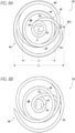
- the present disclosure relates to a sensor implant device comprising a shunt body that forms a fluid conduit, a first anchor structure associated with a first axial end of the shunt body, a second anchor structure associated with a second axial end of the shunt body, and a first sensor device coupled to the first anchor structure, the first anchor structure being configured to hold the first sensor device in a sensing position over a channel area of the fluid conduit.
- the first sensor device when in the sensing position, is aligned with an axis of the fluid conduit.
- the first sensor device when in the sensing position, may be coaxial with the fluid conduit.
- the first anchor structure can be wrapped around a body of the first sensor device.
- the first anchor structure may comprise a first arm that extends from the shunt body over the channel area and holds the first sensor device.
- the first anchor structure can further comprise a second arm that extends from the shunt body over the channel area and holds the first sensor device.
- the first arm and the second arm emanate from opposite sides of the shunt body.
- both the first arm and the second arm may wrap around a circumference of a body of the first sensor device.
- an axial blood flow gap is present between the first sensor device and the first axial end of the shunt body.
- the shunt body comprises a helical wireform.
- the first anchor structure may comprise a spiraled arm that is an integrated form with the helical wireform of the shunt body.
- the shunt body further comprises a cover disposed outside at least a portion of the helical wireform.
- the shunt body can further comprise a cover disposed within at least a portion of the helical wireform.
- the sensor implant device can further comprise a second sensor device coupled to the second anchor structure, the second anchor structure being configured to hold the second sensor device over the channel area of the fluid conduit.
- a sensor transducer of the first sensor device and a sensor transducer of the second sensor device may face in opposite directions.
- the first sensor device and the second sensor device are coaxial.
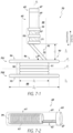
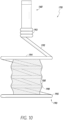
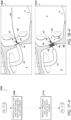
- the present disclosure relates to a sensor implant device comprising a coil wireform.
- the coil wireform comprises, in a deployed configuration, a body portion formed of a plurality of winds of coil of the coil wireform and having a first diameter, a first flange anchor portion emanating from a first axial end of the body portion and having a second diameter that is greater than the first diameter, a first sensor-support arm emanating from the first flange portion and deflected radially over a channel area defined by the body portion, a distal portion of the first sensor-support arm including a sensor-retention means holding a first sensor device, and a second flange anchor portion emanating from a second axial end of the body portion.
- the sensor implant device can further comprise a second sensor-support arm emanating from the second flange portion and deflected radially over the channel area.
- the sensor implant device further comprises a second sensor-support arm emanating from the first flange portion and deflected radially over the channel area, a distal portion of the second sensor-support arm being secured to the first sensor device.
- the first sensor-support arm is deflected axially with respect to an axis of the body portion at a greater angle than a deflection angle of the plurality of winds of coil of the body portion.
- the sensor-retention means can comprise one or more winds of coil.
- the sensor-retention means can comprise a mechanical clip.
- the sensor implant device can further comprise a sealing means associated with the body portion.
- the sealing means can comprise a fabric layer.
- the coil wireform comprises shape memory material configured to assume the deployed configuration when deployed from a delivery catheter.
- the coil wireform can be configured to be compressed into a delivery configuration in which the body portion and the first flange anchor portion have a third diameter that is smaller than the first diameter.
- spatially relative terms are intended to encompass different orientations of the element(s)/structures(s), in use or operation, in addition to the orientations depicted in the drawings.
- an element/structure described as "above” another element/structure may represent a position that is below or beside such other element/structure with respect to alternate orientations of the subject patient or element/structure, and vice-versa.
- the present disclosure relates to systems, devices, and methods for monitoring of one or more physiological parameters of a patient (e.g., blood pressure) using sensor-integrated cardiac shunts and/or other medical implant devices.
- a patient e.g., blood pressure
- the present disclosure relates to cardiac shunts and/or other cardiac implant devices that incorporate or are associated with pressure sensors or other sensor devices.
- the term "associated with” is used herein according to its broad and ordinary meaning.
- first feature, element, component, device, or member is described as being "associated with" a second feature, element, component, device, or member
- such description should be understood as indicating that the first feature, element, component, device, or member is physically coupled, attached, or connected to, integrated with, embedded at least partially within, or otherwise physically related to the second feature, element, component, device, or member, whether directly or indirectly.
- Certain embodiments are disclosed herein in the context of cardiac implant devices. However, although certain principles disclosed herein are particularly applicable to the anatomy of the heart, it should be understood that sensor implant devices in accordance with the present disclosure may be implanted in, or configured for implantation in, any suitable or desirable anatomy.
- the heart In humans and other vertebrate animals, the heart generally comprises a muscular organ having four pumping chambers, wherein the flow thereof is at least partially controlled by various heart valves, namely, the aortic, mitral (or bicuspid), tricuspid, and pulmonary valves.
- the valves may be configured to open and close in response to a pressure gradient present during various stages of the cardiac cycle (e.g., relaxation and contraction) to at least partially control the flow of blood to a respective region of the heart and/or to blood vessels (e.g., pulmonary, aorta, etc.).
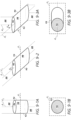
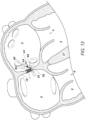
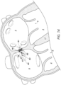
- FIGS 1 and 2 illustrate vertical/frontal and horizontal/superior cross-sectional views, respectively, of an example heart 1 having various features/anatomy relevant to certain aspects of the present inventive disclosure.
- the heart 1 includes four chambers, namely the left atrium 2, the left ventricle 3, the right ventricle 4, and the right atrium 5.
- blood generally flows from the right ventricle 4 into the pulmonary artery 11 via the pulmonary valve 9, which separates the right ventricle 4 from the pulmonary artery 11 and is configured to open during systole so that blood may be pumped toward the lungs and close during diastole to prevent blood from leaking back into the heart from the pulmonary artery 11.
- the pulmonary artery 11 carries deoxygenated blood from the right side of the heart to the lungs.
- the heart 1 includes three additional valves for aiding the circulation of blood therein, including the tricuspid valve 8, the aortic valve 7, and the mitral valve 6.
- the tricuspid valve 8 separates the right atrium 5 from the right ventricle 4.
- the tricuspid valve 8 generally has three cusps or leaflets and may generally close during ventricular contraction (i.e., systole) and open during ventricular expansion (i.e., diastole).
- the mitral valve 6 generally has two cusps/leaflets and separates the left atrium 2 from the left ventricle 3.
- the mitral valve 6 is configured to open during diastole so that blood in the left atrium 2 can flow into the left ventricle 3, and, when functioning properly, closes during systole to prevent blood from leaking back into the left atrium 2.
- the aortic valve 7 separates the left ventricle 3 from the aorta 12.
- the aortic valve 7 is configured to open during systole to allow blood leaving the left ventricle 3 to enter the aorta 12, and close during diastole to prevent blood from leaking back into the left ventricle 3.
- the heart valves may generally comprise a relatively dense fibrous ring, referred to herein as the annulus, as well as a plurality of leaflets or cusps attached to the annulus.
- the size of the leaflets or cusps may be such that when the heart contracts the resulting increased blood pressure produced within the corresponding heart chamber forces the leaflets at least partially open to allow flow from the heart chamber.
- the pressure in the heart chamber subsides, the pressure in the subsequent chamber or blood vessel may become dominant and press back against the leaflets.
- the leaflets/cusps come in apposition to each other, thereby closing the flow passage.
- Disfunction of a heart valve and/or associated leaflets e.g., pulmonary valve disfunction
- the atrioventricular (i.e., mitral and tricuspid) heart valves may further comprise a collection of chordae tendineae and papillary muscles (not shown) for securing the leaflets of the respective valves to promote and/or facilitate proper coaptation of the valve leaflets and prevent prolapse thereof.
- the papillary muscles may generally comprise finger-like projections from the ventricle wall.
- the valve leaflets are connected to the papillary muscles by the chordae tendineae.
- a wall of muscle, referred to as the septum separates the left-side chambers from the right-side chambers.
- an atrial septum wall portion 18 (referred to herein as the "atrial septum,” “atrial septum,” or “septum”) separates the left atrium 2 from the right atrium 5, whereas a ventricular septum wall portion 17 (referred to herein as the “ventricular septum,” “interventricular septum,” or “septum”) separates the left ventricle 3 from the right ventricle 4.
- the inferior tip 14 of the heart 1 is referred to as the apex and is generally located on or near the midclavicular line, in the fifth intercostal space.
- the coronary sinus 16 comprises a collection of veins joined together to form a relatively large vessel that collects blood from the heart muscle (myocardium).
- the ostium of the coronary sinus 16 which can be guarded at least in part by a Thebesian valve in some patients, is open to the right atrium 5, as shown.
- the coronary sinus runs along a posterior aspect of the left atrium 2 and delivers less-oxygenated blood to the right atrium 5.
- the coronary sinus generally runs transversely in the left atrioventricular groove on the posterior side of the heart.
- congestive heart failure is a condition associated with the relatively slow movement of blood through the heart and/or body, which causes the fluid pressure in one or more chambers of the heart to increase.
- the heart does not pump sufficient oxygen to meet the body's needs.
- the various chambers of the heart may respond to pressure increases by stretching to hold more blood to pump through the body or by becoming relatively stiff and/or thickened.
- the walls of the heart can eventually weaken and become unable to pump as efficiently.
- the kidneys may respond to cardiac inefficiency by causing the body to retain fluid.
- congestive heart failure Acute decompensated congestive heart failure is a leading cause of morbidity and mortality, and therefore treatment and/or prevention of congestive heart failure is a significant concern in medical care.
- the treatment and/or prevention of heart failure can advantageously involve the monitoring of pressure in one or more chambers or regions of the heart or other anatomy.
- pressure buildup in one or more chambers or areas of the heart can be associated with congestive heart failure.
- treatments or approaches not involving direct or indirect pressure monitoring may involve measuring or observing other present physiological conditions of the patient, such as measuring body weight, thoracic impedance, right heart catheterization, or the like.
- pulmonary capillary wedge pressure can be measured as a surrogate of left atrial pressure.
- a pressure sensor may be disposed or implanted in the pulmonary artery, and readings associated therewith may be used as a surrogate for left atrial pressure.
- catheter-based pressure measurement in the pulmonary artery or certain other chambers or regions of the heart use of invasive catheters may be required to maintain such pressure sensors, which may be uncomfortable or difficult to implement.
- certain lung-related conditions may affect pressure readings in the pulmonary artery, such that the correlation between pulmonary artery pressure and left atrial pressure may be undesirably attenuated.
- pressure measurements in the right ventricle outflow tract may relate to left atrial pressure as well.
- the correlation between such pressure readings and left atrial pressure may not be sufficiently strong to be utilized in congestive heart failure diagnostics, prevention, and/or treatment.
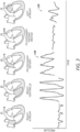
- the E/A ratio which is a marker of the function of the left ventricle of the heart representing the ratio of peak velocity blood flow from gravity in early diastole (the E wave) to peak velocity flow in late diastole caused by atrial contraction (the A wave), can be used as a surrogate for measuring left atrial pressure.
- the E/A ratio may be determined using echocardiography or other imaging technology; generally, abnormalities in the E/A ratio may suggest that the left ventricle cannot fill with blood properly in the period between contractions, which may lead to symptoms of heart failure, as explained above.
- E/A ratio determination generally does not provide absolute pressure measurement values.
- Various methods for identifying and/or treating congestive heart failure involve the observation of worsening congestive heart failure symptoms and/or changes in body weight.
- signs may appear relatively late and/or be relatively unreliable.
- daily bodyweight measurements may vary significantly (e.g., up to 9% or more) and may be unreliable in signaling heart-related complications.
- treatments guided by monitoring signs, symptoms, weight, and/or other biomarkers have not been shown to substantially improve clinical outcomes.
- such treatments may necessitate remote telemedicine systems.
- the present disclosure provides systems, devices, and methods for guiding the administration of medication relating to the treatment of congestive heart failure at least in part by directly monitoring pressure in the left atrium, or other chamber or vessel for which pressure measurements are indicative of left atrial pressure and/or pressure levels in one or more other vessels/chambers, such as for congestive heart failure patients in order to reduce hospital readmissions, morbidity, and/or otherwise improve the health prospects of the patient.
Landscapes
- Health & Medical Sciences (AREA)
- Life Sciences & Earth Sciences (AREA)
- Engineering & Computer Science (AREA)
- Animal Behavior & Ethology (AREA)
- Veterinary Medicine (AREA)
- Public Health (AREA)
- General Health & Medical Sciences (AREA)
- Biomedical Technology (AREA)
- Heart & Thoracic Surgery (AREA)
- Pathology (AREA)
- Surgery (AREA)
- Medical Informatics (AREA)
- Biophysics (AREA)
- Physics & Mathematics (AREA)
- Molecular Biology (AREA)
- Cardiology (AREA)
- Physiology (AREA)
- Vascular Medicine (AREA)
- Computer Networks & Wireless Communication (AREA)
- Otolaryngology (AREA)
- Anesthesiology (AREA)
- Hematology (AREA)
- Ophthalmology & Optometry (AREA)
- Prostheses (AREA)
- External Artificial Organs (AREA)
- Measuring Pulse, Heart Rate, Blood Pressure Or Blood Flow (AREA)
- Electrotherapy Devices (AREA)
Applications Claiming Priority (3)
| Application Number | Priority Date | Filing Date | Title |
|---|---|---|---|
| US202163161385P | 2021-03-15 | 2021-03-15 | |
| EP22717292.1A EP4280940B1 (fr) | 2021-03-15 | 2022-03-03 | Dispositifs d'implant de dérivation dotés de bras de capteur sur canal |
| PCT/US2022/018748 WO2022197454A1 (fr) | 2021-03-15 | 2022-03-03 | Dispositifs d'implant de dérivation dotés de bras de capteur sur canal |
Related Parent Applications (1)
| Application Number | Title | Priority Date | Filing Date |
|---|---|---|---|
| EP22717292.1A Division EP4280940B1 (fr) | 2021-03-15 | 2022-03-03 | Dispositifs d'implant de dérivation dotés de bras de capteur sur canal |
Publications (2)
| Publication Number | Publication Date |
|---|---|
| EP4529834A2 true EP4529834A2 (fr) | 2025-04-02 |
| EP4529834A3 EP4529834A3 (fr) | 2025-04-16 |
Family
ID=81327516
Family Applications (2)
| Application Number | Title | Priority Date | Filing Date |
|---|---|---|---|
| EP22717292.1A Active EP4280940B1 (fr) | 2021-03-15 | 2022-03-03 | Dispositifs d'implant de dérivation dotés de bras de capteur sur canal |
| EP25158429.8A Pending EP4529834A3 (fr) | 2021-03-15 | 2022-03-03 | Dispositifs d'implant de dérivation avec bras de capteur sur canal |
Family Applications Before (1)
| Application Number | Title | Priority Date | Filing Date |
|---|---|---|---|
| EP22717292.1A Active EP4280940B1 (fr) | 2021-03-15 | 2022-03-03 | Dispositifs d'implant de dérivation dotés de bras de capteur sur canal |
Country Status (6)
| Country | Link |
|---|---|
| US (1) | US20230414117A1 (fr) |
| EP (2) | EP4280940B1 (fr) |
| JP (1) | JP2024511986A (fr) |
| CN (1) | CN117098492A (fr) |
| CA (1) | CA3212289A1 (fr) |
| WO (1) | WO2022197454A1 (fr) |
Families Citing this family (4)
| Publication number | Priority date | Publication date | Assignee | Title |
|---|---|---|---|---|
| EP4017384A1 (fr) | 2019-08-22 | 2022-06-29 | Edwards Lifesciences Corporation | Aiguilles de ponction |
| CN121694847A (zh) | 2019-11-14 | 2026-03-20 | 爱德华兹生命科学公司 | 经导管的医疗植入物递送 |
| US12527942B2 (en) | 2021-02-01 | 2026-01-20 | Edwards Lifesciences Corporation | Pulmonary vein shunting |
| WO2026050638A1 (fr) | 2024-08-30 | 2026-03-05 | Edwards Lifesciences Corporation | Procédé et système de gestion de dosage de médicament |
Family Cites Families (11)
| Publication number | Priority date | Publication date | Assignee | Title |
|---|---|---|---|---|
| IL125416A0 (en) * | 1996-02-02 | 1999-03-12 | Transvascular Inc | Methods and apparatus for connecting openings formed in adjacent blood vessels or other anatomical structures |
| WO2005074367A2 (fr) * | 2004-02-03 | 2005-08-18 | Atria Medical Inc. | Dispositif et procede de controle de la pression in vivo |
| US8945209B2 (en) * | 2011-05-20 | 2015-02-03 | Edwards Lifesciences Corporation | Encapsulated heart valve |
| US11304698B2 (en) * | 2016-07-25 | 2022-04-19 | Virender K. Sharma | Cardiac shunt device and delivery system |
| US20180035971A1 (en) * | 2016-08-03 | 2018-02-08 | Pi-Harvest Holding Ag | System And Method For Non-Invasive Measurement Of Pressure Inside A Body Including Intravascular Blood Pressure |
| GB201805309D0 (en) * | 2018-03-29 | 2018-05-16 | Imperial Innovations Ltd | Method and apparatus |
| EP3893731B1 (fr) * | 2018-12-12 | 2023-11-15 | Edwards Lifesciences Corporation | Dispositifs d'implants cardiaques avec capteur de pression intégré |
| CN111317516A (zh) * | 2018-12-14 | 2020-06-23 | 杭州唯强医疗科技有限公司 | 一种可监测腔内压力的封堵装置 |
| JP7377269B2 (ja) * | 2018-12-21 | 2023-11-09 | ダブリュ.エル.ゴア アンド アソシエイツ,インコーポレイティド | インプラント可能な心臓センサ |
| ES2976012T3 (es) * | 2019-02-08 | 2024-07-19 | Edwards Lifesciences Corp | Monitorización directa de la presión cardíaca |
| US11234702B1 (en) * | 2020-11-13 | 2022-02-01 | V-Wave Ltd. | Interatrial shunt having physiologic sensor |
-
2022
- 2022-03-03 EP EP22717292.1A patent/EP4280940B1/fr active Active
- 2022-03-03 EP EP25158429.8A patent/EP4529834A3/fr active Pending
- 2022-03-03 WO PCT/US2022/018748 patent/WO2022197454A1/fr not_active Ceased
- 2022-03-03 JP JP2023556831A patent/JP2024511986A/ja active Pending
- 2022-03-03 CA CA3212289A patent/CA3212289A1/fr active Pending
- 2022-03-03 CN CN202280024298.2A patent/CN117098492A/zh active Pending
-
2023
- 2023-09-13 US US18/466,670 patent/US20230414117A1/en active Pending
Also Published As
| Publication number | Publication date |
|---|---|
| EP4280940A1 (fr) | 2023-11-29 |
| US20230414117A1 (en) | 2023-12-28 |
| EP4280940B1 (fr) | 2025-02-19 |
| CA3212289A1 (fr) | 2022-09-22 |
| WO2022197454A1 (fr) | 2022-09-22 |
| JP2024511986A (ja) | 2024-03-18 |
| EP4529834A3 (fr) | 2025-04-16 |
| CN117098492A (zh) | 2023-11-21 |
Similar Documents
| Publication | Publication Date | Title |
|---|---|---|
| US20230414177A1 (en) | Shunt implant devices with offset sensor arms | |
| US20230371902A1 (en) | Shunt sensor implant devices | |
| EP4280940B1 (fr) | Dispositifs d'implant de dérivation dotés de bras de capteur sur canal | |
| US20240090842A1 (en) | Shunt barrel sensor implant anchoring | |
| US20230389811A1 (en) | Implant devices with shunt channel sensors | |
| US20240399123A1 (en) | Shunt implant with adjustable barrel | |
| US20230181114A1 (en) | Sensor stabilizer | |
| US20240081743A1 (en) | Sensor implant device anchoring | |
| US20240081744A1 (en) | Embedded sensor implant devices | |
| US20250025106A1 (en) | Sensor implant device with stabilizing appendage |
Legal Events
| Date | Code | Title | Description |
|---|---|---|---|
| PUAI | Public reference made under article 153(3) epc to a published international application that has entered the european phase |
Free format text: ORIGINAL CODE: 0009012 |
|
| STAA | Information on the status of an ep patent application or granted ep patent |
Free format text: STATUS: THE APPLICATION HAS BEEN PUBLISHED |
|
| REG | Reference to a national code |
Ref country code: DE Ref legal event code: R079 Free format text: PREVIOUS MAIN CLASS: A61B0005021500 Ipc: A61B0005000000 |
|
| PUAL | Search report despatched |
Free format text: ORIGINAL CODE: 0009013 |
|
| AC | Divisional application: reference to earlier application |
Ref document number: 4280940 Country of ref document: EP Kind code of ref document: P |
|
| AK | Designated contracting states |
Kind code of ref document: A2 Designated state(s): AL AT BE BG CH CY CZ DE DK EE ES FI FR GB GR HR HU IE IS IT LI LT LU LV MC MK MT NL NO PL PT RO RS SE SI SK SM TR |
|
| AK | Designated contracting states |
Kind code of ref document: A3 Designated state(s): AL AT BE BG CH CY CZ DE DK EE ES FI FR GB GR HR HU IE IS IT LI LT LU LV MC MK MT NL NO PL PT RO RS SE SI SK SM TR |
|
| RIC1 | Information provided on ipc code assigned before grant |
Ipc: A61B 5/0215 20060101ALI20250307BHEP Ipc: A61B 5/00 20060101AFI20250307BHEP |
|
| STAA | Information on the status of an ep patent application or granted ep patent |
Free format text: STATUS: REQUEST FOR EXAMINATION WAS MADE |
|
| 17P | Request for examination filed |
Effective date: 20250923 |
|
| STAA | Information on the status of an ep patent application or granted ep patent |
Free format text: STATUS: EXAMINATION IS IN PROGRESS |
|
| 17Q | First examination report despatched |
Effective date: 20251215 |