EP4529875A1 - Modulare lenkbare hülle und katheter - Google Patents
Modulare lenkbare hülle und katheter Download PDFInfo
- Publication number
- EP4529875A1 EP4529875A1 EP24203086.4A EP24203086A EP4529875A1 EP 4529875 A1 EP4529875 A1 EP 4529875A1 EP 24203086 A EP24203086 A EP 24203086A EP 4529875 A1 EP4529875 A1 EP 4529875A1
- Authority
- EP
- European Patent Office
- Prior art keywords
- catheter
- sheath
- shaft
- guiding sheath
- electrical
- Prior art date
- Legal status (The legal status is an assumption and is not a legal conclusion. Google has not performed a legal analysis and makes no representation as to the accuracy of the status listed.)
- Pending
Links
Images


Classifications
-
- A—HUMAN NECESSITIES
- A61—MEDICAL OR VETERINARY SCIENCE; HYGIENE
- A61B—DIAGNOSIS; SURGERY; IDENTIFICATION
- A61B34/00—Computer-aided surgery; Manipulators or robots specially adapted for use in surgery
- A61B34/20—Surgical navigation systems; Devices for tracking or guiding surgical instruments, e.g. for frameless stereotaxis
-
- A—HUMAN NECESSITIES
- A61—MEDICAL OR VETERINARY SCIENCE; HYGIENE
- A61B—DIAGNOSIS; SURGERY; IDENTIFICATION
- A61B18/00—Surgical instruments, devices or methods for transferring non-mechanical forms of energy to or from the body
- A61B18/04—Surgical instruments, devices or methods for transferring non-mechanical forms of energy to or from the body by heating
- A61B18/12—Surgical instruments, devices or methods for transferring non-mechanical forms of energy to or from the body by heating by passing a current through the tissue to be heated, e.g. high-frequency current
- A61B18/14—Probes or electrodes therefor
- A61B18/1492—Probes or electrodes therefor having a flexible, catheter-like structure, e.g. for heart ablation
-
- A—HUMAN NECESSITIES
- A61—MEDICAL OR VETERINARY SCIENCE; HYGIENE
- A61B—DIAGNOSIS; SURGERY; IDENTIFICATION
- A61B17/00—Surgical instruments, devices or methods
- A61B2017/00017—Electrical control of surgical instruments
- A61B2017/00225—Systems for controlling multiple different instruments, e.g. microsurgical systems
-
- A—HUMAN NECESSITIES
- A61—MEDICAL OR VETERINARY SCIENCE; HYGIENE
- A61B—DIAGNOSIS; SURGERY; IDENTIFICATION
- A61B17/00—Surgical instruments, devices or methods
- A61B2017/0046—Surgical instruments, devices or methods with a releasable handle; with handle and operating part separable
- A61B2017/00464—Surgical instruments, devices or methods with a releasable handle; with handle and operating part separable for use with different instruments
-
- A—HUMAN NECESSITIES
- A61—MEDICAL OR VETERINARY SCIENCE; HYGIENE
- A61B—DIAGNOSIS; SURGERY; IDENTIFICATION
- A61B18/00—Surgical instruments, devices or methods for transferring non-mechanical forms of energy to or from the body
- A61B2018/00053—Mechanical features of the instrument of device
- A61B2018/00172—Connectors and adapters therefor
- A61B2018/00178—Electrical connectors
-
- A—HUMAN NECESSITIES
- A61—MEDICAL OR VETERINARY SCIENCE; HYGIENE
- A61B—DIAGNOSIS; SURGERY; IDENTIFICATION
- A61B18/00—Surgical instruments, devices or methods for transferring non-mechanical forms of energy to or from the body
- A61B2018/00315—Surgical instruments, devices or methods for transferring non-mechanical forms of energy to or from the body for treatment of particular body parts
- A61B2018/00345—Vascular system
- A61B2018/00351—Heart
-
- A—HUMAN NECESSITIES
- A61—MEDICAL OR VETERINARY SCIENCE; HYGIENE
- A61B—DIAGNOSIS; SURGERY; IDENTIFICATION
- A61B18/00—Surgical instruments, devices or methods for transferring non-mechanical forms of energy to or from the body
- A61B2018/00571—Surgical instruments, devices or methods for transferring non-mechanical forms of energy to or from the body for achieving a particular surgical effect
- A61B2018/00577—Ablation
-
- A—HUMAN NECESSITIES
- A61—MEDICAL OR VETERINARY SCIENCE; HYGIENE
- A61B—DIAGNOSIS; SURGERY; IDENTIFICATION
- A61B18/00—Surgical instruments, devices or methods for transferring non-mechanical forms of energy to or from the body
- A61B2018/00636—Sensing and controlling the application of energy
- A61B2018/00773—Sensed parameters
- A61B2018/00839—Bioelectrical parameters, e.g. ECG, EEG
-
- A—HUMAN NECESSITIES
- A61—MEDICAL OR VETERINARY SCIENCE; HYGIENE
- A61B—DIAGNOSIS; SURGERY; IDENTIFICATION
- A61B34/00—Computer-aided surgery; Manipulators or robots specially adapted for use in surgery
- A61B34/20—Surgical navigation systems; Devices for tracking or guiding surgical instruments, e.g. for frameless stereotaxis
- A61B2034/2046—Tracking techniques
- A61B2034/2051—Electromagnetic tracking systems
-
- A—HUMAN NECESSITIES
- A61—MEDICAL OR VETERINARY SCIENCE; HYGIENE
- A61B—DIAGNOSIS; SURGERY; IDENTIFICATION
- A61B2217/00—General characteristics of surgical instruments
- A61B2217/002—Auxiliary appliance
- A61B2217/007—Auxiliary appliance with irrigation system
Definitions
- This disclosure relates generally to medical devices, and in particular to navigation and tracking of intralumenal devices, particularly catheters and guiding sheaths.
- Cardiac arrhythmias such as atrial fibrillation (AF)
- AF atrial fibrillation
- regions of cardiac tissue abnormally conduct electric signals to adjacent tissue This disrupts the normal cardiac cycle and causes asynchronous rhythm.
- AF atrial fibrillation
- IRE radiofrequency
- RF radiofrequency
- IRE is an alternative approach to RF ablation.
- IRE short pulses of high voltage electrical signals (pulse field ablation electrical signals) are delivered to tissues; the electrical signals generate an unrecoverable permeabilization of cell membranes. Delivery of IRE energy to tissues using multi-electrode catheters was previously proposed in the patent literature. Examples of systems and devices configured for IRE ablation are disclosed in U.S. Patent Pub. No.
- Regions of cardiac tissue can be mapped by a catheter to identify the abnormal electrical signals.
- Some catheter ablation procedures especially those with persistent atrial fibrillation may be performed using electrophysiology (EP) mapping to target areas of aberrant electrical signals.
- EP mapping may include the use of sensing electrodes configured to monitor electrical signals within the cardiovascular system to pinpoint the location of aberrant conductive tissue sites that are responsible for the arrhythmia. Examples of an EP mapping system are described in U.S. Patent No. 5,738,096 , incorporated herein by reference and attached in the Appendix hereto. Examples of EP mapping catheters are described in U.S. Patent No. 9,907,480 , U.S. Patent Pub. No. 2018/0036078 , and U.S. Patent Pub. No. 2018/0056038 , each of which are incorporated herein by reference and attached in the Appendix hereto.
- some catheter ablation procedures may be performed using an image guided surgery (IGS) system.
- IGS image guided surgery
- the IGS system may enable the physician to visually track the location of the catheter within the patient, in relation to images of anatomical structures within the patient, in real time.
- Some systems may provide a combination of EP mapping and IGS functionalities, including the CARTO 3 ® system by Biosense Webster, Inc. of Irvine, Calif. Examples of catheters that are configured for use with an IGS system are disclosed in U.S. Patent No. 9,480,416 , incorporated herein by reference and attached in the Appendix hereto.
- a guiding sheath having a lumen therethrough is positioned to provide intravenous access to a treatment site and left in place while catheters and other intralumenal devices (e.g., dilator, transseptal needle, guidewire) are exchanged through the lumen of the guiding sheath.
- catheters and other intralumenal devices e.g., dilator, transseptal needle, guidewire
- a guiding sheath, a diagnostic catheter, and a therapeutic catheter may be utilized.
- Such devices include, but are not limited to, the CARTO VIZIGO ® bi-directional guiding sheath, the OCTARAY TM mapping catheter, and the THERMOCOOL SMARTTOUCH ® SF catheter by Biosense Webster, Inc. of Irvine, Calif.
- Systems disclosed herein include a steerable catheter or guiding sheath and modular catheter inserts that can be coupled to the steerable catheter or guiding sheath (herein referred as guiding sheath).
- the guiding sheath includes a handle that may include an electrical connector configured to couple to an electrical connector of the modular catheter insert so that electrical signals measured at, and/or delivered to a target area pass through the handle of the guiding sheath.
- the guiding sheath further includes a shaft with a lumen therethrough and may include navigation sensors coupled to a distal portion of the shaft.
- the catheter insert can be configured to couple to the guiding sheath such that a position of a distal portion of the catheter insert can be determined based on electrical signals from the navigation sensors on the distal portion of the guiding sheath.
- the system is configured such that the modular catheter inserts can be interchanged during a medical procedure.
- a diagnostic catheter insert and an ablation diagnostic catheter insert can be interchanged during a medical procedure.
- the diagnostic catheter insert can be delivered through the guiding sheath to a target area and the diagnostic catheter can be coupled to the guiding sheath.
- the location of an end effector of the diagnostic catheter can be determined based on signals from navigation sensor on the distal portion of the guiding sheath.
- Cardiac electrical signals of the heart can be detected by electrodes disposed on the end effector of the diagnostic catheter insert.
- the cardiac electrical signals can be transmitted to a computational system via electrical connection between the diagnostic catheter insert and the guiding sheath.
- the distal portion of the guiding sheath can be articulated to move the end effector of the diagnostic catheter insert across target tissue to detect electrical signals at various locations.
- the diagnostic catheter insert can then be decoupled from the guiding sheath, and the end effector can be retracted proximally through the shaft of the guiding sheath to decouple the diagnostic catheter insert from the guiding sheath.
- the ablation catheter insert can be inserted into the guiding sheath and coupled to the guiding sheath.
- the location of an end effector of the ablation catheter insert can be determined based on signals from the navigation sensor on the distal portion of the guiding sheath.
- Electrical signals to ablate tissue can be transmitted through electrical connection between the ablation catheter insert and the guiding sheath base and to the end effector of the ablation catheter insert.
- the distal portion of the guiding sheath can be articulated to move the end effector of the ablation catheter insert across target tissue to ablate tissue at various locations.
- the ablation catheter insert can be decoupled from the guiding sheath to allow additional catheter inserts to be coupled to the guiding sheath as needed.
- the guiding sheath can further be configured to accommodate other intralumenal devices such as a dilator, transseptal needle, and/or guidewire.
- One exemplary system can include a guiding sheath and at least one catheter insert.
- the guiding sheath includes a sheath shaft extending along a longitudinal axis, a handle coupled to a proximal end of the sheath shaft, a first modular electrical port, and a system electrical port.
- the catheter insert includes a catheter shaft configured to traverse through a lumen of the sheath shaft, a proximal hub coupled to a proximal end of the catheter shaft, an electrode assembly coupled to a distal portion of the catheter shaft, and a second modular electrical port configured to mate with the first modular electrical port of the guiding sheath to pass electrical signals between the electrode assembly and the system electrical port via connection of the first and second modular electrical ports.
- An exemplary guiding sheath can include a sheath shaft, a handle, a system electrical port, and a modular electrical port.
- the sheath shaft extends along a longitudinal axis and has a lumen configured to receive a catheter shaft.
- the handle is coupled to a proximal end of the sheath shaft.
- the modular electrical port is configured to electrically connect the system electrical port to an electrode coupled to the catheter shaft.
- An exemplary catheter insert includes a catheter shaft extending along a longitudinal axis, a proximal hub coupled to a proximal end of the catheter shaft, an electrode assembly coupled to a distal portion of the catheter shaft, and a modular electrical port configured to mate with an electrical port of a guiding sheath to pass electrical signals between the electrode assembly and the electrical port of the guiding sheath.
- An exemplary pulmonary vein diagnostic and treatment kit includes a guiding sheath, a first catheter insert, and a second catheter insert.
- the guiding sheath includes a sheath shaft extending along a longitudinal axis, a handle coupled to a proximal end of the sheath shaft, a first modular electrical port, and a system electrical port.
- the first catheter insert includes a first catheter shaft configured to traverse through a lumen of the sheath shaft, a first proximal hub coupled to a proximal end of the first catheter shaft, a first electrode assembly coupled to a distal portion of the first catheter shaft, and a second modular electrical port configured to mate with the first modular electrical port of the guiding sheath to pass electrical signals between the first electrode assembly and the system electrical port via connection of the first and second modular electrical ports.
- the second catheter insert includes a second catheter shaft configured to traverse through the lumen of the sheath shaft, a second proximal hub coupled to a proximal end of the second catheter shaft, a second electrode assembly coupled to a distal portion of the second catheter shaft, and a third modular electrical port configured to mate with the first modular electrical port of the guiding sheath to pass electrical signals between the second electrode assembly and the system electrical port via connection of the first and third electrical ports.
- the terms "patient,” “host,” “user,” and “subject” refer to any human or animal subject and are not intended to limit the systems or methods to human use, although use of the subject invention in a human patient represents a preferred embodiment.
- proximal indicates a location closer to the operator whereas “distal” indicates a location further away to the operator or physician.
- Systems and methods disclosed herein are configured to perform a catheter-based medical procedure utilizing multiple catheter inserts.
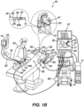
- Figures 1A and 1B are illustrations of an exemplary catheter-based electrophysiology mapping and ablation system 10 utilizing a modular catheter system 100.
- Figure 1A illustrates a diagnostic catheter insert 60a coupled to a guiding sheath 40 at a diagnostic step of a medical procedure
- Figure 1B illustrates a therapeutic catheter insert 60b (also referred to herein as an ablation catheter insert) coupled to the guiding sheath 40 at a treatment step of the medical procedure.
- the guiding sheath 40 can be percutaneously inserted by a physician 24 through the patient's vascular system into a chamber or vascular structure of a heart 12.
- a distal portion of the guiding sheath 40 can be positioned in the left or right atrium near a desired location in the heart 12.
- intravascular devices such as a dilator, transseptal needle, and/or guidewire can be inserted into the guiding sheath 40 to access a target treatment site.
- the sheath inserts 60a, 60b can be sequentially inserted into the guiding sheath 40 so that an electrode assembly 70, 80 coupled to a distal portion of a shaft of the respective catheter insert 60a, 60b can be brought into contact with tissue at or near the target treatment site.
- the catheter inserts 60a, 60b can be exchanged during the medical procedure as needed.
- the diagnostic catheter insert 60a illustrated in Figure 1A is configured to sense Intracardiac Electrogram (IEGM) signals.
- IEGM Intracardiac Electrogram
- the physician 24 brings the electrode assembly 80 of an end effector of the catheter insert 60a into contact with the heart wall for sensing a target site in the heart 12.
- the electrode assembly 80 includes one and preferably multiple electrodes 81 optionally distributed over a plurality of spines 82 and configured to sense the IEGM signals.
- the ablation catheter insert 60b illustrated in Figure 1B is configured to provide electrical signal to tissue to ablate tissue and interrupt aberrant electrical signals propagating through heart tissue.
- the electrode assembly 70 of the ablation catheter insert 60b includes at least one ablation electrode 71.
- the physician 24 bring the ablation electrode 71 into contact with tissue of the heart 12 so that ablation energy can be provided to the ablation electrode 71 to ablate the tissue.
- each catheter insert 60a, 60b includes a proximal hub 64 that can be electrically and mechanically coupled to a handle 41 of the guiding sheath 41.
- the guiding sheath 40 includes a system electrical port 45 configured to provide electrical communication to a patient interface unit (PIU) 30.
- the patient interface unit (PIU) 30 is an interface configured to establish electrical communication between catheters, electrophysiological equipment, power supply, and a workstation 14 for controlling operation of system 10.
- Electrophysiological equipment of the system 10 may include for example, the guiding sheath 40, additional catheter inserts, catheters, a location pad 25, body surface ECG electrodes 18, electrode patches 38, an ablation energy generator 13, and a recorder 11.
- the PIU 30 includes processing capability for implementing real-time computations of location of the modular catheter system 100, for performing ECG calculations, and/or for controlling electrical signals provided to perform ablation.
- the system 10 can further include an adapter 90 configured to provide electrical connection between the system electrical port 45 and the PIU 30.
- electrical signals sensed by electrodes 81 of the electrode assembly 80 can be transmitted through conductors in the shaft of the diagnostic catheter insert 60a, through the electrical connection between the proximal hub 64 and handle 41, through the system electrical port 45, through the adapter 90, and to the PIU 30.
- the system 10 can include an ablation energy generator 13 that is adapted to conduct ablative energy to one or more of electrodes at a distal tip of a catheter configured for ablating.
- Energy produced by the ablation energy generator 13 may include, but is not limited to, radiofrequency (RF) energy or pulsed-field ablation (PFA) energy, including monopolar or bipolar high-voltage DC pulses as may be used to effect irreversible electroporation (IRE), or combinations thereof.
- RF radiofrequency
- PFA pulsed-field ablation
- IRE irreversible electroporation
- electrical signals can be provided from the ablation energy generator 13, to the PIU 30, through the adapter 90, through the system electrical port 45, through the electrical connection between the proximal hub 64 and the handle 41, through conductors in the shaft of the ablation catheter insert 60b, to the electrode 71 of the electrode assembly 70, and to the target tissue.
- the guiding sheath 40 includes a navigation sensor 50 coupled to a distal portion of the sheath shaft 42.
- the navigation sensor 50 is configured for tracking position and orientation of distal portion of the catheter insert 60a, 60b including the respective electrode assembly 70, 80.
- the navigation sensor 50 is preferably a magnetic based position sensor including three magnetic coils for sensing three-dimensional (3D) position and orientation.
- a magnetic based position sensor 50 may be operated together with a location pad 25 including a plurality of magnetic coils 32 configured to generate magnetic fields in a predefined working volume.
- Real time position of the distal portion of the respective catheter insert 60a, 60b may be tracked based on magnetic fields generated with a location pad 25 and sensed by a magnetic based position sensor 50. Details of the magnetic based position sensing technology are described in U.S. PatentNos. 5,391,199; 5,443,489; 5,558,091; 6,172,499; 6,239,724; 6,332,089; 6,484,118; 6,618,612; 6,690,963; 6,788,967; 6,892,091 incorporated by reference herein.
- the distal portion of the shaft 42 of the guiding sheath 40 can optionally include electrodes 49 configured to sense electrical signals from the external environment such as fluids and/or tissue. As illustrated, the electrodes 49 may be configured as ring electrodes.
- the system 10 includes one or more electrode patches 38 positioned for skin contact on the patient 23 to establish location reference for location pad 25 as well as impedance-based tracking of electrodes 49. For impedance-based tracking, electrical current is directed toward electrodes 49 and sensed at electrode skin patches 38 so that the location of each electrode can be triangulated via the electrode patches 38. Details of the impedance-based location tracking technology are described in US Patent Nos. 7,536,218 ; 7,756,576 ; 7,848,787 ; 7,869,865 ; and 8,456,182 incorporated by reference herein.
- the catheter inserts 60a, 60b and guiding sheath 40 can be sized, shaped, and otherwise configured such that when the proximal hub 64 of the respective catheter insert 60a, 60b is coupled the handle 41 of the guiding sheath 40, the respective distal portion of the catheter insert 60a, 60b is at a predetermined position (or approximate predetermined position) in relation to the navigation sensor 50 (and optionally electrodes 49).
- the PIU 30 can be configured to determine the position of the distal portion of the catheter insert 60a, 60b (and thereby electrodes 71, 81 of the electrode assembly 70, 80 of the respective catheter insert 60a, 60b) based at least in part on the position of the distal portion of sheath shaft 42.
- the navigation sensor 50 of the sheath shaft is configured to provide an indication of a position of the distal portion of the catheter insert 60a, 60b.
- the electrodes 71, 81 of a respective catheter insert 60a, 60b may be utilized for impedance-based location tracking of the respective electrode assembly 70, 80.
- an electrode assembly can include flexible features, that may be configured to move, within a predefined space, in relation to the navigation sensor 50 (and optionally electrodes 49 on the sheath shaft 42), and impedance-based location tracking can be used to determine a location of electrodes within the predefined space.
- the electrode assembly 80 illustrated in Figure 1A includes electrodes 81 coupled to flexible spines 82 each joined to a distal end 66 of the shaft of the diagnostic catheter insert 60a.
- the flexible spines 82 are able to move within a predefined space near the distal end 66 of the shaft of the diagnostic catheter insert 60a.
- the distal end 66 of the shaft of the diagnostic catheter insert 60a is at a predetermined position in relation to the navigation sensor 50 (and optionally electrodes 49 on the sheath shaft 42), and therefore the predefined space in which the flexible spines 82 are able to move is at a predetermined position in relation to the navigation sensor 50 (and optionally electrodes 49 on the sheath shaft 42).
- the electrodes 81 on the spines 82 can be located with impedance-based tracking to provide a more precise location of each electrode 81 within the predefined space.
- the catheter inserts 60a, 60b need not include a navigation sensor.
- the distal portion of the catheter shaft insert 60a, 60b lacks an inductive navigation sensor.
- the catheter insert 60a, 60b may include an inductive navigation sensor.
- the distal end of the sheath shaft 42 may be determined based at least in part on the inductive navigation sensor of the catheter insert 60a, 60a, and the sheath shaft 42 need not include the illustrated guiding sensor 50.
- the catheter inserts 60a, 60b and guiding sheath 40 can be sized, shaped, and otherwise configured such that when the proximal hub 64 of the respective catheter insert 60a, 60b is coupled the handle 41 of the guiding sheath 40, the respective distal portion of the catheter insert 60a, 60b is at a predetermined position (or approximate predetermined position) in relation to the inductive navigation sensor of the catheter insert.
- both the guiding sheath shaft 42 and the catheter insert 60a, 60b can include a respective inductive navigation sensor.
- the workstation 14 includes memory, processor unit with memory or storage with appropriate operating software loaded therein, and user interface capability.
- the workstation 14 can be configured to provide multiple functions, optionally including (1) modeling the endocardial anatomy in three-dimensions (3D) and rendering the model or an anatomical map 20 for display on a display device 27; (2) displaying on the display device 27 activation sequences (or other data) compiled from recorded electrograms 21 in representative visual indicia or imagery superimposed on the rendered anatomical map 20; (3) displaying real-time location and orientation of the distal portion of catheter-based devices within the heart chamber; and (4) displaying on the display device 27 sites of interest such as places where ablation energy has been applied.
- the workstation 14 can be configured to provide an end effector visualization 17 that indicates real-time location and orientation of a respective electrode assembly 70, 80 and configured to provide a sheath visualization 16 that indicates real-time location and orientation of the distal portion of the sheath shaft 42.
- a recorder 11 displays electrograms 21 captured with body surface ECG electrodes 18 and intracardiac electrograms (IEGM) captured with electrodes 26 of the catheter 14.
- the recorder 11 may include pacing capability for pacing the heart rhythm and/or may be electrically connected to a standalone pacer.
- the system 10 may further include an irrigation system 15 configured to provide irrigation fluid to the guiding sheath 40 and/or catheter insert 60a, 60b.
- the handle 41 of the guiding sheath 40 can be connected to the irrigation system 15 by an irrigation line 19.
- the proximal hub 64 of the ablation catheter insert 60b can be connected to the irrigation system 15 by an irrigation line 22.
- the modular system 100 can be configured such that irrigation fluid can be provided to the lumen of the guiding sheath independent of irrigation provided to the ablation catheter insert 60b.
- the system 10 may further include an implant and implant delivery system (not illustrated).
- LAAO left atrial appendage occlusion
- the implant can be delivered with the implant delivery system through the guiding sheath 40 to a treatment site.
- the navigation sensor 50 can be utilized to determine a position of the sheath distal end 48.
- the implant can be inserted into the hemostasis valve 51 of the guiding sheath 40, manipulated by the implant delivery system to push the implant distally through the sheath shaft 42, and expelled from the distal end 48 of the guiding sheath 40 at the treatment site.
- the implant can then be deployed, and the delivery system can be retracted proximally from the guiding sheath 40.
- FIG 2 is an illustration of an exemplary modular catheter system 100 including a guiding sheath 40 and a catheter insert 60.
- the modular catheter system 100 is configured as described in relation to Figures 1A and 1B and is illustrated including an ablation catheter insert configured similarly to the ablation catheter insert 60b illustrated in Figure 1B .
- the guiding sheath 40 includes a handle 41, a sheath shaft 42 extending distally from the handle 41, a modular electrical port 46, a system electrical port 45, a navigation sensor 50, and ring electrodes 49 configured as disclosed in relation to Figures 1A and 1B .
- the catheter insert 60 includes a proximal hub 60 and an electrode assembly 70 configured as disclosed in relation to Figure 1B .
- the modular catheter system 100 can further include a diagnostic catheter insert 60 including an electrode assembly 80 configured as disclosed in relation to Figure 1A that can be exchanged for the illustrated catheter insert 60.
- the guiding sheath 40 includes a first modular electrical port 46
- the catheter insert 60 includes a second modular electrical port 61 configured to mate with the first modular electrical port 46 to pass electrical signals between the electrode assembly 70 and the system electrical port 45.
- the first and second modular electrical ports 46, 61 may further be configured to mechanically couple to each other to thereby fix a position of the proximal hub 64 in relation to the sheath handle 41.
- a distal end 72 of the sheath insert 60 is inserted into an opening in a hemostatic valve 51 at a proximal end of the sheath handle 41, the shaft 62 of the catheter insert 60 is pushed distally through the sheath shaft 47.
- the second modular electrical port 61 of the catheter insert 60 is inserted into the first modular electrical port 46 of the guiding sheath 40. Once coupled, a distal portion of the catheter insert 60, including the electrode assembly 70 extends a predetermined length from a distal end 48 of the sheath shaft 47.
- the sheath shaft 42 extends along a longitudinal axis A-A.
- the sheath shaft 42 may be configured to deflect from the longitudinal axis as illustrated.
- the sheath handle 41 may include a deflection knob 43 configured to be manipulated to deflect the distal portion of the sheath shaft 42 and a distal portion of the catheter shaft 62 from the longitudinal axis.
- the modular catheter system 100 can be configured such that the distal portion of the catheter shaft 62 is unable to deflect independently from the guiding sheath 40.
- the catheter insert 60 can lack a mechanism (e.g., puller wires) to deflect the distal portion of the catheter shaft from the longitudinal axis A-A, and the deflection of the sheath shaft 42 alone can be sufficient to position the electrode assembly 70 at desired locations during a medical procedure.
- a mechanism e.g., puller wires
- the guiding sheath 40 may further include an irrigation port 44 configured to couple to the irrigation system 15 ( Figures 1A and 1B ).
- the catheter insert 60 may further include an irrigation port 63 configured to couple to the irrigation system 15 ( Figures 1A and 1B ).
- the catheter insert 60 need not include a navigation sensor and associated electrical conductors through the catheter shaft 62, and the catheter insert 60 need not include deflection mechanism such as puller wires. Therefore, the catheter insert 60 can be made cheaper and/or with a smaller French size compared to a respective diagnostic or therapeutic catheter configured with independent navigation and/or deflection.
- the reduced French size of the catheter insert 60 may further result in the outer diameter of the guiding sheath 40 being smaller than comparable guiding sheaths known in the art, thereby resulting in easier intravenous translation and smaller incision size.
- the guiding sheath 40 and catheter insert 60 may be easier to be manipulated by the physician 23 than a comparable system including a guiding sheath and catheter that are independent of each other.
- the proximal hub 64 may essentially act as an extension of the guiding sheath handle 41 so that there is only one handle to manipulate rather than two used in existing procedures.
- the electrical connection between the guiding sheath 40 and catheter insert allows for a single electrical cable to provide electrical connection to the PIU 30, reducing potential tangle of electrical cables compared to system which have separate electrical cables for the guiding sheath and catheter.
- Figure 3A is an illustration of the proximal portion of the exemplary catheter insert 60 showing the proximal hub 64, second modular electrical port 61, and proximal portion of the catheter shaft 62.
- the catheter insert 60 as illustrated further includes the optional irrigation port 63.
- FIG 3B is an illustration of a distal portion of an exemplary ablation catheter insert including an electrode assembly 70 with an ablation electrode 71.
- the ablation electrode 71 is preferably configured to provide irrigation fluid to a treatment site, and therefore the ablation catheter insert preferably includes the irrigation port 63 ( Figure 3A ).
- the ablation catheter insert can include various end effector configurations including balloon, basket, ray, mesh, and other suitable electrode arrangements as understood by a person skilled in the pertinent art.
- Figure 3C is an illustration of a distal portion of an exemplary diagnostic catheter insert including an electrode assembly 80 with electrodes 81 configured to sense IEGM signals.
- the diagnostic catheter may not require irrigation and therefore may lack the irrigation port 63 ( Figure 3A ).
- the diagnostic catheter insert can include various end effector configurations including balloon, basket, ray, mesh, and other suitable electrode arrangement as understood by a person skilled in the pertinent art.
- the catheter insert 60 may be configured to perform visualization of a treatment area.
- a visualization catheter insert may include an ultrasound probe approximate a distal end of the visualization catheter. The distal portion of such a visualization catheter insert can be determined as generally described in relation to catheter insert 60.
- Figure 4 is an illustration of an isometric view of the modular catheter system 100.
- the shaft 62 of the catheter insert 60 has been inserted into the proximal end of the hemostasis valve 51 of the guiding sheath 40.
- the catheter insert 60 can be moved in the distal direction in relation to the guiding sheath 40 to mate the second modular electrical port 61 of the catheter insert 60 to the first modular electrical port 46 of the guiding sheath 40.
- FIG 5 is an illustration of components of an exemplary catheter-based electrophysiology mapping and ablation system configured similarly to the system 10 disclosed in relation to Figures 1A and 1B .
- the adapter 90 includes a sheath electrical connector 91, a splitter 92, a diagnostic electrode connector 93, a mapping connector 94, and an ablation generator connector 95.
- the sheath electrical connector 91 is configured to electrically couple to the system electrical port 45 of the guiding sheath 40.
- the diagnostic electrode connector 93 is configured to transmit electrical signals from an electrode assembly of a diagnostic catheter insert to the PIU 30.
- the mapping connector 94 is configured to electrically couple the navigation sensor 50 (and optionally the electrodes 49) to the PIU 30.
- the ablation generator connector 95 is configured to electrically couple the ablation electrode(s) 71 to the PIU 30.
- the splitter 92 is configured to route the electrical signals between the singular sheath electrical connector 91 and the three PIU electrical connectors 93, 94, 95.
- Figures 6A and 6B are illustrations of an exemplary assembly including a guiding sheath 40 and a catheter insert 60 with an adjustable shaft length.
- the proximal hub 64 of the catheter insert 60 includes an extension lever 65 configured to move the catheter shaft 62 proximally and distally by a length L1 so that the catheter shaft 62 can extend and retract by the length L1 from the distal end 48 of the guiding sheath 40.
- the proximal hub 64 may further be configured with an electrical sensor in electrical communication with the second modular electrical port 61, and the electrical sensor can be configured to provide an electrical signal indicative of length of extension of the distal portion of the catheter insert 60 from the distal end 48 of the guiding sheath 40.
- the electrical sensor may be electrically coupled to the second modular electrical port 61 ( Figure 4 ) so that it may be electrically coupled to a computational system, such as the workstation 13 or PIU 30 ( Figures 1A and 1B ) via the connection between the first modular electrical port 46 and the second modular electrical port 61.
- the computational system can be configured to determine a position of the electrode assembly 70 of the catheter insert 60 based at least in part on the length of extension of the distal portion of the catheter insert 60.
- the illustrated electrode assembly 70 can have an end effector design similar to existing ablation and/or diagnostic catheters, alternatives thereto, and variations thereof, including those not yet developed, as understood by a person skilled in the pertinent art.
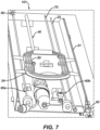
- Figure 7 is an illustration of an exemplary pulmonary vein diagnostic and treatment kit 101.
- the kit 101 includes a guiding sheath 40, a diagnostic catheter insert 60a, and a therapeutic catheter insert 60b configured as disclosed elsewhere herein.
- the treatment kit 101 can further include accessories such as a dilator 33 and a guide wire 34 (illustrated in a guidewire sheath 35).
- the distal portions of the illustrated catheter inserts 60, 60a, 60b can have various alternative end effector configurations including balloon, basket, ray, mesh, and other suitable electrode arrangement as understood by a person skilled in the pertinent art.
- the illustrated electrode assembly 70, 80 can have various alternative end effector designs that may be similar to existing ablation and/or diagnostic catheters, alternatives thereto, and variations thereof, including those not yet developed, as understood by a person skilled in the pertinent art.
Landscapes
- Health & Medical Sciences (AREA)
- Surgery (AREA)
- Life Sciences & Earth Sciences (AREA)
- Engineering & Computer Science (AREA)
- Heart & Thoracic Surgery (AREA)
- Animal Behavior & Ethology (AREA)
- Veterinary Medicine (AREA)
- Public Health (AREA)
- General Health & Medical Sciences (AREA)
- Biomedical Technology (AREA)
- Nuclear Medicine, Radiotherapy & Molecular Imaging (AREA)
- Medical Informatics (AREA)
- Molecular Biology (AREA)
- Cardiology (AREA)
- Physics & Mathematics (AREA)
- Plasma & Fusion (AREA)
- Otolaryngology (AREA)
- Robotics (AREA)
- Surgical Instruments (AREA)
- Measurement And Recording Of Electrical Phenomena And Electrical Characteristics Of The Living Body (AREA)
- Electrotherapy Devices (AREA)
- Media Introduction/Drainage Providing Device (AREA)
Applications Claiming Priority (1)
| Application Number | Priority Date | Filing Date | Title |
|---|---|---|---|
| US18/477,418 US12611263B2 (en) | 2023-09-28 | Modular steerable sheath and catheter |
Publications (1)
| Publication Number | Publication Date |
|---|---|
| EP4529875A1 true EP4529875A1 (de) | 2025-04-02 |
Family
ID=92926107
Family Applications (1)
| Application Number | Title | Priority Date | Filing Date |
|---|---|---|---|
| EP24203086.4A Pending EP4529875A1 (de) | 2023-09-28 | 2024-09-27 | Modulare lenkbare hülle und katheter |
Country Status (4)
| Country | Link |
|---|---|
| EP (1) | EP4529875A1 (de) |
| JP (1) | JP2025059104A (de) |
| CN (1) | CN119700271A (de) |
| IL (1) | IL315788A (de) |
Citations (30)
| Publication number | Priority date | Publication date | Assignee | Title |
|---|---|---|---|---|
| US5391199A (en) | 1993-07-20 | 1995-02-21 | Biosense, Inc. | Apparatus and method for treating cardiac arrhythmias |
| US5558091A (en) | 1993-10-06 | 1996-09-24 | Biosense, Inc. | Magnetic determination of position and orientation |
| US5738096A (en) | 1993-07-20 | 1998-04-14 | Biosense, Inc. | Cardiac electromechanics |
| US6172499B1 (en) | 1999-10-29 | 2001-01-09 | Ascension Technology Corporation | Eddy current error-reduced AC magnetic position measurement system |
| US6239724B1 (en) | 1997-12-30 | 2001-05-29 | Remon Medical Technologies, Ltd. | System and method for telemetrically providing intrabody spatial position |
| US6332089B1 (en) | 1996-02-15 | 2001-12-18 | Biosense, Inc. | Medical procedures and apparatus using intrabody probes |
| US20020133149A1 (en) * | 2001-03-17 | 2002-09-19 | Arthrocare Corporation | Electrosurgical systems and methods for hair transplantation and epilation |
| US6484118B1 (en) | 2000-07-20 | 2002-11-19 | Biosense, Inc. | Electromagnetic position single axis system |
| US6618612B1 (en) | 1996-02-15 | 2003-09-09 | Biosense, Inc. | Independently positionable transducers for location system |
| US6690963B2 (en) | 1995-01-24 | 2004-02-10 | Biosense, Inc. | System for determining the location and orientation of an invasive medical instrument |
| US6892091B1 (en) | 2000-02-18 | 2005-05-10 | Biosense, Inc. | Catheter, method and apparatus for generating an electrical map of a chamber of the heart |
| US7536218B2 (en) | 2005-07-15 | 2009-05-19 | Biosense Webster, Inc. | Hybrid magnetic-based and impedance-based position sensing |
| US7756576B2 (en) | 2005-08-26 | 2010-07-13 | Biosense Webster, Inc. | Position sensing and detection of skin impedance |
| US7848787B2 (en) | 2005-07-08 | 2010-12-07 | Biosense Webster, Inc. | Relative impedance measurement |
| US7869865B2 (en) | 2005-01-07 | 2011-01-11 | Biosense Webster, Inc. | Current-based position sensing |
| US8456182B2 (en) | 2008-09-30 | 2013-06-04 | Biosense Webster, Inc. | Current localization tracker |
| US20130282007A1 (en) * | 2010-12-27 | 2013-10-24 | Cathrx Ltd | Modular catheter |
| US20160095650A1 (en) * | 2013-04-22 | 2016-04-07 | Cathrx Ltd | An ablation catheter |
| US9480416B2 (en) | 2014-01-17 | 2016-11-01 | Biosense Webster (Israel) Ltd. | Signal transmission using catheter braid wires |
| US20180036078A1 (en) | 2014-11-20 | 2018-02-08 | Biosense Webster (Israel) Ltd. | Catheter with soft distal tip for mapping and ablating tubular region |
| US20180056038A1 (en) | 2016-08-24 | 2018-03-01 | Biosense Webster (Israel ) LTD. | Catheter with bipole electrode spacer and related methods |
| US9907480B2 (en) | 2016-02-08 | 2018-03-06 | Biosense Webster (Israel) Ltd. | Catheter spine assembly with closely-spaced bipole microelectrodes |
| US20190159855A1 (en) * | 2017-10-24 | 2019-05-30 | Karl Storz Se & Co. Kg | Handling device for a microinvasive medical instrument |
| US20210161592A1 (en) | 2019-12-03 | 2021-06-03 | Biosense Webster (Israel) Ltd. | Pulse Generator for Irreversible Electroporation |
| US20210169567A1 (en) | 2019-12-09 | 2021-06-10 | Biosense Webster (Israel) Ltd. | Irreversible-electroporation (ire) balloon catheter with membrane-insulated high-voltage balloon wires |
| US20210169550A1 (en) | 2019-12-05 | 2021-06-10 | Biosense Webster (Israel) Ltd. | Generating and interleaving of irreversible-electroporation and radiofrequnecy ablation (ire/rfa) waveforms |
| US20210169568A1 (en) | 2019-12-09 | 2021-06-10 | Biosense Webster (Israel) Ltd. | Oriented irreversible-electroporation (ire) pulses to compensate for cell size and orientation |
| US20210177503A1 (en) | 2019-12-11 | 2021-06-17 | Biosense Webster (Israel) Ltd. | Regulating delivery of irreversible electroporation pulses according to transferred energy |
| US20210186604A1 (en) | 2019-12-24 | 2021-06-24 | Biosense Webster (Israel) Ltd. | Irreversible electroporation (ire) based on field, contact force and time |
| US20210196372A1 (en) | 2019-12-31 | 2021-07-01 | Biosense Webster (Israel) Ltd. | Using irrigation on irreversible-electroporation (ire) electrodes to prevent arcing |
-
2024
- 2024-09-19 IL IL315788A patent/IL315788A/en unknown
- 2024-09-27 CN CN202411359035.4A patent/CN119700271A/zh active Pending
- 2024-09-27 EP EP24203086.4A patent/EP4529875A1/de active Pending
- 2024-09-27 JP JP2024168647A patent/JP2025059104A/ja active Pending
Patent Citations (32)
| Publication number | Priority date | Publication date | Assignee | Title |
|---|---|---|---|---|
| US5391199A (en) | 1993-07-20 | 1995-02-21 | Biosense, Inc. | Apparatus and method for treating cardiac arrhythmias |
| US5443489A (en) | 1993-07-20 | 1995-08-22 | Biosense, Inc. | Apparatus and method for ablation |
| US5738096A (en) | 1993-07-20 | 1998-04-14 | Biosense, Inc. | Cardiac electromechanics |
| US5558091A (en) | 1993-10-06 | 1996-09-24 | Biosense, Inc. | Magnetic determination of position and orientation |
| US6690963B2 (en) | 1995-01-24 | 2004-02-10 | Biosense, Inc. | System for determining the location and orientation of an invasive medical instrument |
| US6332089B1 (en) | 1996-02-15 | 2001-12-18 | Biosense, Inc. | Medical procedures and apparatus using intrabody probes |
| US6618612B1 (en) | 1996-02-15 | 2003-09-09 | Biosense, Inc. | Independently positionable transducers for location system |
| US6788967B2 (en) | 1997-05-14 | 2004-09-07 | Biosense, Inc. | Medical diagnosis, treatment and imaging systems |
| US6239724B1 (en) | 1997-12-30 | 2001-05-29 | Remon Medical Technologies, Ltd. | System and method for telemetrically providing intrabody spatial position |
| US6172499B1 (en) | 1999-10-29 | 2001-01-09 | Ascension Technology Corporation | Eddy current error-reduced AC magnetic position measurement system |
| US6892091B1 (en) | 2000-02-18 | 2005-05-10 | Biosense, Inc. | Catheter, method and apparatus for generating an electrical map of a chamber of the heart |
| US6484118B1 (en) | 2000-07-20 | 2002-11-19 | Biosense, Inc. | Electromagnetic position single axis system |
| US20020133149A1 (en) * | 2001-03-17 | 2002-09-19 | Arthrocare Corporation | Electrosurgical systems and methods for hair transplantation and epilation |
| US7869865B2 (en) | 2005-01-07 | 2011-01-11 | Biosense Webster, Inc. | Current-based position sensing |
| US7848787B2 (en) | 2005-07-08 | 2010-12-07 | Biosense Webster, Inc. | Relative impedance measurement |
| US7536218B2 (en) | 2005-07-15 | 2009-05-19 | Biosense Webster, Inc. | Hybrid magnetic-based and impedance-based position sensing |
| US7756576B2 (en) | 2005-08-26 | 2010-07-13 | Biosense Webster, Inc. | Position sensing and detection of skin impedance |
| US8456182B2 (en) | 2008-09-30 | 2013-06-04 | Biosense Webster, Inc. | Current localization tracker |
| US20130282007A1 (en) * | 2010-12-27 | 2013-10-24 | Cathrx Ltd | Modular catheter |
| US20160095650A1 (en) * | 2013-04-22 | 2016-04-07 | Cathrx Ltd | An ablation catheter |
| US9480416B2 (en) | 2014-01-17 | 2016-11-01 | Biosense Webster (Israel) Ltd. | Signal transmission using catheter braid wires |
| US20180036078A1 (en) | 2014-11-20 | 2018-02-08 | Biosense Webster (Israel) Ltd. | Catheter with soft distal tip for mapping and ablating tubular region |
| US9907480B2 (en) | 2016-02-08 | 2018-03-06 | Biosense Webster (Israel) Ltd. | Catheter spine assembly with closely-spaced bipole microelectrodes |
| US20180056038A1 (en) | 2016-08-24 | 2018-03-01 | Biosense Webster (Israel ) LTD. | Catheter with bipole electrode spacer and related methods |
| US20190159855A1 (en) * | 2017-10-24 | 2019-05-30 | Karl Storz Se & Co. Kg | Handling device for a microinvasive medical instrument |
| US20210161592A1 (en) | 2019-12-03 | 2021-06-03 | Biosense Webster (Israel) Ltd. | Pulse Generator for Irreversible Electroporation |
| US20210169550A1 (en) | 2019-12-05 | 2021-06-10 | Biosense Webster (Israel) Ltd. | Generating and interleaving of irreversible-electroporation and radiofrequnecy ablation (ire/rfa) waveforms |
| US20210169567A1 (en) | 2019-12-09 | 2021-06-10 | Biosense Webster (Israel) Ltd. | Irreversible-electroporation (ire) balloon catheter with membrane-insulated high-voltage balloon wires |
| US20210169568A1 (en) | 2019-12-09 | 2021-06-10 | Biosense Webster (Israel) Ltd. | Oriented irreversible-electroporation (ire) pulses to compensate for cell size and orientation |
| US20210177503A1 (en) | 2019-12-11 | 2021-06-17 | Biosense Webster (Israel) Ltd. | Regulating delivery of irreversible electroporation pulses according to transferred energy |
| US20210186604A1 (en) | 2019-12-24 | 2021-06-24 | Biosense Webster (Israel) Ltd. | Irreversible electroporation (ire) based on field, contact force and time |
| US20210196372A1 (en) | 2019-12-31 | 2021-07-01 | Biosense Webster (Israel) Ltd. | Using irrigation on irreversible-electroporation (ire) electrodes to prevent arcing |
Also Published As
| Publication number | Publication date |
|---|---|
| JP2025059104A (ja) | 2025-04-09 |
| IL315788A (en) | 2025-04-01 |
| US20250107853A1 (en) | 2025-04-03 |
| CN119700271A (zh) | 2025-03-28 |
Similar Documents
| Publication | Publication Date | Title |
|---|---|---|
| EP3915501B1 (de) | Intraluminale referenzelektrode für kardiovaskuläre behandlungsvorrichtung | |
| US20210369132A1 (en) | Intraluminal reference electrode for cardiovascular treatment apparatus | |
| US20240245359A1 (en) | Catheter with insert-molded microelectrode | |
| EP3944830B1 (de) | System mit einem fokalen katheter mit kontaktkraft und temperatursensoren | |
| EP3810004B1 (de) | Elektrische erdungsfunktion für den spülfluidweg in einer katheteranordnung | |
| US12611263B2 (en) | Modular steerable sheath and catheter | |
| US20240390056A1 (en) | End effector having elongated support member with curved electrode landing region | |
| EP4529875A1 (de) | Modulare lenkbare hülle und katheter | |
| US20240197392A1 (en) | Multi-electrode basket end effector of a catheter | |
| EP4385442A1 (de) | Katheter mit zugringkoppler | |
| US20250049345A1 (en) | Impedance-based navigation of sheath | |
| US20250213821A1 (en) | Devices for catheter articulation systems | |
| US20250213822A1 (en) | Devices for catheter articulation systems | |
| EP4393426A2 (de) | Multielektrodenkatheter mit verschachteltem substrat | |
| EP4342405B1 (de) | Katheterschaft mit mehrebenengelenk und rotation | |
| EP4393433A1 (de) | Korbkatheter mit kompatibler spülung und versetzten elektroden | |
| US20240335648A1 (en) | Hemostasis valve for expandable-type catheter | |
| US20250195131A1 (en) | Simplified basket catheters having multiple spines | |
| EP4578415A1 (de) | Strömungsumlenker für einen katheter | |
| EP4578413A1 (de) | Medizinische sonde zur navigation in blutgefässen mit kleinem durchmesser | |
| US20250025624A1 (en) | Flexible irrigation tube for a medical catheter | |
| CN120168087A (zh) | 标测和消融导管 |
Legal Events
| Date | Code | Title | Description |
|---|---|---|---|
| PUAI | Public reference made under article 153(3) epc to a published international application that has entered the european phase |
Free format text: ORIGINAL CODE: 0009012 |
|
| STAA | Information on the status of an ep patent application or granted ep patent |
Free format text: STATUS: THE APPLICATION HAS BEEN PUBLISHED |
|
| AK | Designated contracting states |
Kind code of ref document: A1 Designated state(s): AL AT BE BG CH CY CZ DE DK EE ES FI FR GB GR HR HU IE IS IT LI LT LU LV MC ME MK MT NL NO PL PT RO RS SE SI SK SM TR |
|
| STAA | Information on the status of an ep patent application or granted ep patent |
Free format text: STATUS: REQUEST FOR EXAMINATION WAS MADE |
|
| 17P | Request for examination filed |
Effective date: 20251001 |