EP4530003A1 - Matériau en poudre pour fabrication additive et procédé de fabrication de produit fabriqué de manière additive à l'aide d'un matériau en poudre - Google Patents
Matériau en poudre pour fabrication additive et procédé de fabrication de produit fabriqué de manière additive à l'aide d'un matériau en poudre Download PDFInfo
- Publication number
- EP4530003A1 EP4530003A1 EP24203281.1A EP24203281A EP4530003A1 EP 4530003 A1 EP4530003 A1 EP 4530003A1 EP 24203281 A EP24203281 A EP 24203281A EP 4530003 A1 EP4530003 A1 EP 4530003A1
- Authority
- EP
- European Patent Office
- Prior art keywords
- powder material
- additive
- powder
- metal
- mass
- Prior art date
- Legal status (The legal status is an assumption and is not a legal conclusion. Google has not performed a legal analysis and makes no representation as to the accuracy of the status listed.)
- Pending
Links
Images

Classifications
-
- B—PERFORMING OPERATIONS; TRANSPORTING
- B22—CASTING; POWDER METALLURGY
- B22F—WORKING METALLIC POWDER; MANUFACTURE OF ARTICLES FROM METALLIC POWDER; MAKING METALLIC POWDER; APPARATUS OR DEVICES SPECIALLY ADAPTED FOR METALLIC POWDER
- B22F1/00—Metallic powder; Treatment of metallic powder, e.g. to facilitate working or to improve properties
- B22F1/12—Metallic powder containing non-metallic particles
-
- B—PERFORMING OPERATIONS; TRANSPORTING
- B22—CASTING; POWDER METALLURGY
- B22F—WORKING METALLIC POWDER; MANUFACTURE OF ARTICLES FROM METALLIC POWDER; MAKING METALLIC POWDER; APPARATUS OR DEVICES SPECIALLY ADAPTED FOR METALLIC POWDER
- B22F10/00—Additive manufacturing of workpieces or articles from metallic powder
- B22F10/20—Direct sintering or melting
- B22F10/28—Powder bed fusion, e.g. selective laser melting [SLM] or electron beam melting [EBM]
-
- B—PERFORMING OPERATIONS; TRANSPORTING
- B33—ADDITIVE MANUFACTURING TECHNOLOGY
- B33Y—ADDITIVE MANUFACTURING, i.e. MANUFACTURING OF THREE-DIMENSIONAL [3D] OBJECTS BY ADDITIVE DEPOSITION, ADDITIVE AGGLOMERATION OR ADDITIVE LAYERING, e.g. BY 3D PRINTING, STEREOLITHOGRAPHY OR SELECTIVE LASER SINTERING
- B33Y70/00—Materials specially adapted for additive manufacturing
-
- C—CHEMISTRY; METALLURGY
- C22—METALLURGY; FERROUS OR NON-FERROUS ALLOYS; TREATMENT OF ALLOYS OR NON-FERROUS METALS
- C22C—ALLOYS
- C22C1/00—Making non-ferrous alloys
- C22C1/04—Making non-ferrous alloys by powder metallurgy
- C22C1/05—Mixtures of metal powder with non-metallic powder
- C22C1/051—Making hard metals based on borides, carbides, nitrides, oxides or silicides; Preparation of the powder mixture used as the starting material therefor
-
- C—CHEMISTRY; METALLURGY
- C22—METALLURGY; FERROUS OR NON-FERROUS ALLOYS; TREATMENT OF ALLOYS OR NON-FERROUS METALS
- C22C—ALLOYS
- C22C29/00—Alloys based on carbides, oxides, nitrides, borides, or silicides, e.g. cermets, or other metal compounds, e.g. oxynitrides, sulfides
- C22C29/02—Alloys based on carbides, oxides, nitrides, borides, or silicides, e.g. cermets, or other metal compounds, e.g. oxynitrides, sulfides based on carbides or carbonitrides
- C22C29/06—Alloys based on carbides, oxides, nitrides, borides, or silicides, e.g. cermets, or other metal compounds, e.g. oxynitrides, sulfides based on carbides or carbonitrides based on carbides, but not containing other metal compounds
-
- C—CHEMISTRY; METALLURGY
- C22—METALLURGY; FERROUS OR NON-FERROUS ALLOYS; TREATMENT OF ALLOYS OR NON-FERROUS METALS
- C22C—ALLOYS
- C22C29/00—Alloys based on carbides, oxides, nitrides, borides, or silicides, e.g. cermets, or other metal compounds, e.g. oxynitrides, sulfides
- C22C29/02—Alloys based on carbides, oxides, nitrides, borides, or silicides, e.g. cermets, or other metal compounds, e.g. oxynitrides, sulfides based on carbides or carbonitrides
- C22C29/06—Alloys based on carbides, oxides, nitrides, borides, or silicides, e.g. cermets, or other metal compounds, e.g. oxynitrides, sulfides based on carbides or carbonitrides based on carbides, but not containing other metal compounds
- C22C29/10—Alloys based on carbides, oxides, nitrides, borides, or silicides, e.g. cermets, or other metal compounds, e.g. oxynitrides, sulfides based on carbides or carbonitrides based on carbides, but not containing other metal compounds based on titanium carbide
-
- B—PERFORMING OPERATIONS; TRANSPORTING
- B22—CASTING; POWDER METALLURGY
- B22F—WORKING METALLIC POWDER; MANUFACTURE OF ARTICLES FROM METALLIC POWDER; MAKING METALLIC POWDER; APPARATUS OR DEVICES SPECIALLY ADAPTED FOR METALLIC POWDER
- B22F2301/00—Metallic composition of the powder or its coating
- B22F2301/15—Nickel or cobalt
-
- B—PERFORMING OPERATIONS; TRANSPORTING
- B22—CASTING; POWDER METALLURGY
- B22F—WORKING METALLIC POWDER; MANUFACTURE OF ARTICLES FROM METALLIC POWDER; MAKING METALLIC POWDER; APPARATUS OR DEVICES SPECIALLY ADAPTED FOR METALLIC POWDER
- B22F2301/00—Metallic composition of the powder or its coating
- B22F2301/35—Iron
-
- B—PERFORMING OPERATIONS; TRANSPORTING
- B22—CASTING; POWDER METALLURGY
- B22F—WORKING METALLIC POWDER; MANUFACTURE OF ARTICLES FROM METALLIC POWDER; MAKING METALLIC POWDER; APPARATUS OR DEVICES SPECIALLY ADAPTED FOR METALLIC POWDER
- B22F2302/00—Metal Compound, non-Metallic compound or non-metal composition of the powder or its coating
- B22F2302/10—Carbide
-
- B—PERFORMING OPERATIONS; TRANSPORTING
- B33—ADDITIVE MANUFACTURING TECHNOLOGY
- B33Y—ADDITIVE MANUFACTURING, i.e. MANUFACTURING OF THREE-DIMENSIONAL [3D] OBJECTS BY ADDITIVE DEPOSITION, ADDITIVE AGGLOMERATION OR ADDITIVE LAYERING, e.g. BY 3D PRINTING, STEREOLITHOGRAPHY OR SELECTIVE LASER SINTERING
- B33Y10/00—Processes of additive manufacturing
-
- B—PERFORMING OPERATIONS; TRANSPORTING
- B33—ADDITIVE MANUFACTURING TECHNOLOGY
- B33Y—ADDITIVE MANUFACTURING, i.e. MANUFACTURING OF THREE-DIMENSIONAL [3D] OBJECTS BY ADDITIVE DEPOSITION, ADDITIVE AGGLOMERATION OR ADDITIVE LAYERING, e.g. BY 3D PRINTING, STEREOLITHOGRAPHY OR SELECTIVE LASER SINTERING
- B33Y70/00—Materials specially adapted for additive manufacturing
- B33Y70/10—Composites of different types of material, e.g. mixtures of ceramics and polymers or mixtures of metals and biomaterials
-
- Y—GENERAL TAGGING OF NEW TECHNOLOGICAL DEVELOPMENTS; GENERAL TAGGING OF CROSS-SECTIONAL TECHNOLOGIES SPANNING OVER SEVERAL SECTIONS OF THE IPC; TECHNICAL SUBJECTS COVERED BY FORMER USPC CROSS-REFERENCE ART COLLECTIONS [XRACs] AND DIGESTS
- Y02—TECHNOLOGIES OR APPLICATIONS FOR MITIGATION OR ADAPTATION AGAINST CLIMATE CHANGE
- Y02P—CLIMATE CHANGE MITIGATION TECHNOLOGIES IN THE PRODUCTION OR PROCESSING OF GOODS
- Y02P10/00—Technologies related to metal processing
- Y02P10/25—Process efficiency
Definitions
- peaks other than those derived from the powder material before laser light irradiation are not included in the XRD spectrum of the additive-manufactured product obtained by additive manufacturing including laser light irradiation, and is not subjected to further heat treatment.
- peaks other than those derived from the powder material before laser light irradiation are not included in the XRD spectra of both the additive-manufactured product which is not subjected to heat treatment and the additive-manufactured product (sintered body) which is subjected to heat treatment.
- the "powder material” refers to a powdered material used for additive manufacturing.
- the powder material disclosed herein is a carbide ceramic/metal-containing powder material, that is, a powder material for additive manufacturing in which the carbide ceramic and the metal are the main constituent components (that is, the powder material for additive manufacturing in which the largest constituent components in the entire powder material on a mass basis are carbide ceramic + metal).
- the powder material for additive manufacturing of the present aspect more than 50 mass% of the entire powder material on a mass basis is composed of the carbide ceramic and the metal.
- raw material particles refers to particles constituting the powder at the raw material stage (raw material powder) used to form the powder material disclosed herein.
- average particle size concerning a powder material means an average particle size (50% volume average particle size, D 50 ) at an integrated value of 50% in a volume-based particle size distribution measured by a particle size distribution measuring device based on a laser scattering/diffraction method.
- the powder material disclosed herein is a carbide ceramic/metal-containing powder material containing a carbide ceramic and a metal.
- the carbide ceramic is not particularly limited as long as an additive-manufactured product obtained by additive manufacturing including laser light irradiation using a powder material for additive manufacturing containing the carbide ceramic exhibits a predetermined XRD spectrum, or the solid solubility of the carbide ceramic in the metal described later has a predetermined value.
- the carbide ceramic is not particularly limited, and examples thereof include vanadium carbide (VC), niobium carbide (NbC), tantalum carbide (TaC), titanium carbide (TiC), zirconium carbide (ZrC), hafnium carbide (HfC), silicon carbide (SiC), boron carbide (B 4 C), and the like.
- the carbide ceramic may be a composite carbide containing two or more kinds of metals. Any one of the carbide ceramic may be contained alone, or two or more thereof may be contained in combination.
- the carbide ceramic has a standard enthalpy of formation of -90 kJ/mol or less.
- a reaction between the carbide ceramic and the metal is less likely to occur in a rapid cooling solidification process including melting both the carbide ceramic and the metal, such as additive manufacturing. Therefore, it is possible to avoid the reaction product between the carbide ceramic and the metal from causing a decrease in the performance of the additive-manufactured product.
- the standard enthalpy of formation of the carbide ceramic is more preferably -95 kJ/mol or less, and still more preferably -100 kJ/mol or less.
- the lower limit value of the standard enthalpy of formation of the carbide ceramic is not particularly limited, but is, for example, - 250 kJ/mol or more.
- Examples of the carbide ceramic having a standard enthalpy of formation of -90 kJ/mol or less include TiC (-185 kJ/mol), VC (-102 kJ/mol), ZrC (-203 kJ/mol), NbC (-139 kJ/mol), TaC (-146 kJ/mol), and the like.
- the standard enthalpy of formation of at least one kind of carbide ceramic is preferably in the above range, and the standard enthalpies of formation of all the carbide ceramics are more preferably in the above range.
- the carbide ceramic has a melting point of 2700°C or higher.
- a reaction between the carbide ceramic and the metal is less likely to occur in a rapid cooling solidification process including melting both the carbide ceramic and the metal, such as additive manufacturing. Therefore, it is possible to avoid the reaction product between the carbide ceramic and the metal from causing a decrease in the performance of the additive-manufactured product.
- the melting point of the carbide ceramic is more preferably 2750°C or higher, and still more preferably 2800°C or higher.
- the upper limit value of the melting point of the carbide ceramic is not particularly limited, but is, for example, 4000°C or lower, preferably 3950°C or lower, and more preferably 3900°C or lower.
- the additive-manufactured product can be more efficiently manufactured by the additive manufacturing.
- the carbide ceramic having a melting point of 2700°C or higher include TiC (3250°C), VC (2830°C), ZrC (3180°C), NbC (3500°C), HfC (3900°C), TaC (3880°C), and the like.
- the melting point of at least one kind of carbide ceramic is preferably in the above range, and the melting points of all the carbide ceramics are more preferably in the above range.
- the melting point of the carbide ceramic As the value of the melting point of the carbide ceramic, a value described in Superhard Alloys and Sintered Hard Materials: Fundamentals and Applications, edited by Hisashi Suzuki, Maruzen Publishing Co., Ltd. (February 1986 ) can be used.
- the carbide ceramic contains one or more compounds selected from the group consisting of a carbide of a Group 4 element and a carbide of a Group 5 element.
- the carbide ceramic is one or more compounds selected from the group consisting of a carbide of a Group 4 element and a carbide of a Group 5 element.
- the Group 4 element include Ti, Zr, Hf, and the like, and examples of the carbide of the Group 4 element include TiC, ZrC, HfC, and the like.
- Examples of the Group 5 element include V, Nb, Ta, and the like, and examples of the carbide of the Group 5 element include VC, NbC, TaC, and the like.
- a ratio of a total amount of the carbide of the Group 4 element and the carbide of the Group 5 element to a total amount of the carbide ceramic is, for example, 40 mass% or more, preferably 50 mass% or more, more preferably more than 50 mass%, still more preferably 55 mass% or more, still more preferably 60 mass% or more, still more preferably 65 mass% or more, still more preferably 70 mass% or more, still more preferably 75 mass% or more, still more preferably 80 mass% or more, still more preferably 85 mass% or more, still more preferably 90 mass% or more, still more preferably 95 mass% or more, still more preferably 97 mass% or more, still more preferably 99 mass% or more, and still more preferably 100 mass%.
- the carbide ceramic consists only of one or more compounds selected from the group consisting of the carbide of the Group 4 element and the carbides of the Group 5 element.
- carbide ceramic powder made of raw material particles of the carbide ceramic which can serve as the raw material of the powder material of the present aspect
- various commercially available carbide ceramic powder materials for cemented carbide formation are used.
- raw material particles of carbide ceramic having an average particle size (D 50 ) of 0.05 to 10 um, preferably 0.1 to 8 ⁇ m, and more preferably 0.2 to 5 um can be used.
- the metal is not particularly limited as long as the additive-manufactured product using the metal exhibits a predetermined XRD spectrum or the solid solubility of carbide ceramic has a predetermined value.
- the metal include magnesium (Mg), aluminum (Al), titanium (Ti), chromium (Cr), manganese (Mn), iron (Fe), cobalt (Co), nickel (Ni), copper (Cu), zinc (Zn), zirconium (Zr), gold (Au), silver (Ag), platinum (Pt), iridium (Ir), bismuth (Bi), niobium (Ni), molybdenum (Mo), tin (Sn), tungsten (W), lead (Pb), alloys thereof, and the like.
- the metal is preferably one or more selected from the group consisting of Co, Ni, and Fe, and more preferably Co or Ni. That is, in a preferred embodiment, the metal contains one or more selected from the group consisting of cobalt, nickel, and iron. In a preferred embodiment, the metal is one or more selected from the group consisting of cobalt, nickel, and iron.
- the XRD spectrum of an additive-manufactured product obtained by additive manufacturing including laser light irradiation using the powder material does not include peaks other than those derived from the powder material before the laser light irradiation, or the solid solubility of the carbide ceramic in the metal at 1250°C is 8 mass% or less.
- the solid solubility value is a value of a percentage of a mass of the carbide ceramic that can be solid-solved in a unit mass of the metal.
- the means for obtaining the powder material in which the additive-manufactured product exhibits a predetermined XRD spectrum is not particularly limited, but can be achieved, for example, by selecting the carbide ceramic and the metal such that the solid solubility of the carbide ceramic in the metal at 1250°C is 8 mass% or less. As a result, the reaction between the carbide ceramic and the metal is less likely to occur during the additive manufacturing, and thus peaks other than the peaks derived from the raw material of the powder material are less likely to appear in the XRD spectrum of the additive-manufactured product.
- the solid solubility of the carbide ceramic in the metal at 1250°C exceeds 8 mass%, the reaction product between the carbide ceramic and the metal is generated in additive manufacturing, and thus the performance of the additive-manufactured product may deteriorate.
- the solid solubility of the carbide ceramic in the metal at 1250°C is preferably 7 mass% or less, more preferably less than 7 mass%, and still more preferably 6 mass% or less.
- the lower limit value of the solid solubility of the carbide ceramic in the metal at 1250°C is not particularly limited, but is, for example, 0.1 mass% or more, preferably 0.5 mass% or more, and more preferably 1 mass% or more.
- Examples of such combinations of the carbide ceramic and the metal include TiC/Co (1 mass%), TiC/Ni (5 mass%), TiC/Fe (0.5 mass%), VC/Co (6 mass%), VC/Ni (7 mass%), VC/Fe (3 mass%), NbC/Co (5 mass%), NbC/Ni (3 mass%), NbC/Fe (1 mass%), TaC/Co (3 mass%), TaC/Ni (5 mass%), TaC/Fe (0.5 mass%), and the like.
- solid solubility of the carbide ceramic in the metal a solid solubility value of a single carbide ceramic (however, materials that share common constituent elements, such as VC and V 4 C 3 , are considered to be a single carbide ceramic) in a single metal is used.
- the solid solubility value of the carbide ceramic in the metal at 1250°C the value described in F. W. Glaser: Met. Progr., 67 (1955) 77-82 is used. Note that compounds that share common constituent elements, such as VC and V 4 C 3 , can be considered to have the same solid solubility value.
- the component constituting more than 50 mass% of the total carbide ceramics may have a solid solubility value at 1250°C of 8 mass% or less with respect to the component constituting more than 50 mass% of the total metals.
- the mass ratio of the carbide ceramic having the highest mass ratio is 50 mass% or less of the total carbide ceramics, all carbide ceramics may have the above-described solid solubility values.
- the mass ratio of the metal having the highest mass ratio is 50 mass% or less of the total metals, all metals may have the above-described solid solubility value.
- the solid solubility value of the carbide ceramic in the metal at 1250°C is 8 mass% or less.
- the powder material for additive manufacturing contains cobalt and a carbide ceramic having a solid solubility in cobalt at 1250°C of 8 mass% or less. In one embodiment, the powder material for additive manufacturing contains nickel and a carbide ceramic having a solid solubility in nickel at 1250°C of 8 mass% or less.
- metal powders used for powder metallurgy and manufacturing of a cemented carbide material can be used without particular limitation.
- a metal powder having an average particle size (D 50 ) of 1 um or more (for example, 2 um or more) and about 10 um or less (for example, 5 um or less) can be preferably used.
- a content of the metal is 8 to 43 volume% with respect to a total amount of the carbide ceramic and the metal.
- the content of the metal is less than 8 volume%, the melted metal cannot be sufficiently wet-spread on the surfaces of the particles of the carbide ceramic at the time of additive manufacturing, and a dense additive-manufactured product cannot be manufactured. As a result, an additive-manufactured product having high hardness cannot be obtained.
- the content of the metal exceeds 43 volume%, the content of the carbide ceramic becomes relatively small, and thus an additive-manufactured product having high hardness cannot be obtained.
- the content of the metal is preferably 10 to 40 volume%, more preferably 15 to 35 volume%, still more preferably 15 to 30 volume%, still more preferably 18 to 29 volume%, and still more preferably 19 to 27 volume% with respect to the total amount of the carbide ceramic and the metal.
- the content of the metal in the powder material of the present embodiment does not vary from that at the stage of preparation, during the process of sintering granulation, in both mass-based and volume-based values.
- the content of the metal may be 8 to 43 volume%, preferably 10 to 40 volume%, more preferably 15 to 35 volume%, and still more preferably 20 to 30 volume% with respect to the total amount of the powder material.
- the content of the metal is preferably 5 to 45 mass%, more preferably 10 to 45 mass%, still more preferably 15 to 40 mass%, and still more preferably 18 to 39 mass% with respect to the total amount of the carbide ceramic and the metal. In one embodiment, the content of the metal is preferably 5 to 45 mass%, more preferably 10 to 45 mass%, still more preferably 15 to 40 mass%, and still more preferably 18 to 39 mass% with respect to the total amount of the powder material.
- the powder material of the present aspect may contain optional components other than the carbide ceramic and the metal.
- the optional component include a carbon material (for example, a particulate solid carbon material).
- the solid carbon material include graphite, carbon black (acetylene black, Ketjen black, and the like), activated carbon, carbon fiber (PAN-based carbon fiber, pitch-based carbon fiber, graphite fiber, and the like), and nanocarbons (carbon nanotubes, fullerenes, graphene, diamond fine particles, and the like).
- a binder, a dispersant, a surfactant, an inorganic pigment, an organic pigment, and the like may be contained as optional components.
- the binder, dispersant, surfactant, inorganic pigment, and organic pigment are not particularly limited, and known materials can be appropriately selected.
- the content (mass basis) of the carbide ceramic in the entire powder material is not particularly limited, but the content of the carbide ceramic is preferably more than 50 mass%, more preferably 55 mass% or more, still more preferably 60 mass% or more, and still more preferably 61 mass% or more, in the entire powder material. In addition, the content of the carbide ceramic is preferably 95 mass% or less, and more preferably 90 mass% or less, still more preferably 85 mass% or less, and still more preferably 82 mass% or less, with respect to the entire powder material.
- a content of one or more compounds selected from the group consisting of a carbide of a Group 4 element and a carbide of a Group 5 element is preferably more than 50 mass%, and more preferably 60 mass% or more with respect to the entire powder material.
- the content of the carbides (WC, W 2 C, Co 3 W 3 C, Cr 3 W 3 , Cr 7 C 3 , Cr 3 C 2 , Mo 2 C, and the like) containing a Group 6 element is preferably 5 mass% or less, more preferably 3 mass% or less, still more preferably 1 mass% or less, and most preferably 0 mass% with respect to the entire powder material.
- the total amount of the carbide ceramic and the metal is preferably 90 mass% or more, more preferably 95 mass% or more, still more preferably 97 mass% or more, still more preferably 98 mass% or more, and still more preferably 99 mass% or more (upper limit: 100 mass%) with respect to the entire powder material.
- the average particle size (50% volume average particle size, D 50 ) of the powder material (for example, granulated sintered particles described later) according to the present embodiment is not particularly limited, and can have a size suitable for the standard of the additive manufacturing apparatus to be used.
- the average particle size of the powder material may be a size suitable for supplying the powder material in additive manufacturing.
- the upper limit of the average particle size of the powder material may be, for example, more than 200 um in a case where the average particle size is larger, but is typically 200 um or less.
- the upper limit of the average particle size of the powder material is preferably 150 um or less, more preferably 100 um or less, and still more preferably 40 um or less.
- the filling ratio of the powder material may improve, for example, in the manufacturing area.
- the denseness of the three-dimensional additive-manufactured product to be manufactured can be suitably increased.
- the surface roughness (Ra) of the three-dimensional additive-manufactured product to be manufactured can be reduced, and the effect of improving the dimensional accuracy can be obtained.
- the lower limit of the average particle size of the powder material is not particularly limited as long as there is no influence on the fluidity of the powder material. However, in consideration of handling at the time of forming the powder material and fluidity of the powder material, the lower limit of the average particle size can be 1 um or more, and is preferably 5 um or more, more preferably 10 um or more.
- the fluidity of the powder material is improved.
- the powder material can be favorably supplied to the manufacturing apparatus, and the finishing of the three-dimensional additive-manufactured product to be prepared becomes favorable, which is preferable.
- a volume-based cumulative 97% particle size (D 97 ) and a volume-based cumulative 3% particle size (D 3 ) of the powder material are not particularly limited, but from the viewpoint of finishing of the three-dimensional additive-manufactured product of the powder material according to the present embodiment, a value obtained by dividing the cumulative 97% particle size (D 97 ) by the cumulative 3% particle size (D 3 ) may be 2 or more and 6 or less, and preferably 3 or more and 5 or less.
- the average particle size (50% volume average particle size, D 50 ) of the powder material (for example, the granulated sintered particles described later), the cumulative 97% particle size and the cumulative 3% particle size can be determined by the method described in Examples described later.
- the strength of the powder material (hereinafter, referred to as "granule strength") in the powder material (for example, granulated sintered particles described later) according to the present embodiment is not particularly limited, but is preferably 1kgf/mm 2 or more, more preferably 5kgf/mm 2 or more, and particularly preferably 10kgf/mm 2 or more (for example, 20kgf/mm 2 or more).
- granule strength is not particularly limited, but is preferably 1kgf/mm 2 or more, more preferably 5kgf/mm 2 or more, and particularly preferably 10kgf/mm 2 or more (for example, 20kgf/mm 2 or more).
- the granule strength is preferably less than 500kgf/mm 2 , more preferably 300kgf/mm 2 or less, still more preferably 200kgf/mm 2 or less, and particularly preferably 100kgf/mm 2 or less (for example, 50kgf/mm 2 or less).
- the granule strength of the powder material (for example, the granulated sintered particles described later) can be determined by the method described in Examples described later.
- the bulk density of the powder material (for example, granulated sintered particles described later) according to the present embodiment is not particularly limited, and is, for example, 0.5 to 5 g/cm 3 . Within the above range, the filling ratio of the powder material can be improved in the manufacturing area. As a result, the denseness of the three-dimensional additive-manufactured product to be manufactured can be suitably increased. In addition, handling at the time of forming a powder material and fluidity of the powder material are excellent.
- the bulk density of the powder material (for example, the granulated sintered particles described later) can be determined by the method described in Examples described later.
- the powder material (for example, granulated sintered particles described later) according to the present embodiment is not particularly limited, but preferably has a repose angle of less than 39°.
- the repose angle can be one of indices that have been widely adopted to indicate a fluidity of a powder in the related art. Then, for example, it can be an index that can practically reflect a spontaneous fluidity when the powder material is conveyed in a supply apparatus and a manufacturing apparatus. Therefore, it is possible to realize a powder material having a high fluidity by defining the repose angle to be small. As a result, a powder material capable of preparing a homogeneous three-dimensional additive-manufactured product with higher productivity can be obtained.
- the lower limit of the repose angle is not particularly limited, but the repose angle is preferably 20° or more from the viewpoint of making the powder material less likely to scatter or facilitating control of a supply amount of the powder material.
- the repose angle of the powder material (for example, the granulated sintered particles described later) can be determined by the method described in Examples described later.
- the powder material disclosed herein can be prepared, for example, by mixing raw material particles made of a carbide ceramic and raw material particles made of a metal together with optional components as necessary.
- the material formed of such a mixed powder is a typical example of the carbide ceramic/metal-containing powder material disclosed herein.
- a more suitable powder material is a powder material formed of granulated sintered particles in which the carbide ceramic and the metal are mixed.
- the powder material is a powder material formed of granulated sintered particles as secondary particles formed by mixing and granulating raw material particles (primary particles) of the respective components and then sintering the granulated particles, and in the secondary particles, the respective primary particles are three-dimensionally bonded with gaps.
- the term "primarily" indicates that the granulated sintered particles account for preferably 90 mass% or more, more preferably 95 mass% or more, still more preferably 98 mass% or more (upper limit: 100 mass%) of the powder material.
- a granulation sintering method for suitably manufacturing such granulated sintered particles will be described, but the method is not limited thereto.
- the granulation sintering method is a method in which raw material particles are granulated into the form of secondary particles and then sintered to bond (sinter) the raw material particles.
- granulation can be performed using, for example, a granulation method such as dry granulation or wet granulation.
- a granulation method such as dry granulation or wet granulation.
- the granulation method include a tumbling granulation method, a fluidized bed granulation method, a mixing granulation method, a crushing granulation method, a melt granulation method, a spray granulation method, a microemulsion granulation method, and the like.
- a spray granulation method is exemplified as a suitable granulation method.
- a powder material can be manufactured by the following procedure. That is, first, raw material particles of respective kinds corresponding to the carbide ceramic and the metal are prepared, and the surfaces thereof are stabilized with a protective agent or the like as necessary. Then, the raw material particles are dispersed in an appropriate solvent together with, for example, a binder as an optional component and/or spacer particles, made of an organic material, or the like to prepare a spray liquid.
- the dispersion of the raw material particles in the solvent can be performed using, for example, a mixer such as a homogenizer or a blade type stirrer, a disperser, or the like.
- droplets are formed from the sprayed liquid using an ultrasonic sprayer or the like, and the droplets are placed on an air flow and passed through a spray drying device (spray dryer), whereby granulated particles can be formed.
- the obtained granulated particles are introduced into a predetermined firing furnace and sintered to obtain a powder material including granulated sintered particles in the form of secondary particles in which primary particles are bonded with gaps.
- the primary particles may have substantially the same size and shape as the raw material particles, or the raw material particles may be grown and bonded by firing.
- the raw material particles and the binder are in a uniform mixed state, and the raw material particles are bound by the binder to constitute mixed particles.
- the raw material particles and the spacer particles are bound by a binder in a uniform mixed state to form mixed particles. Then, by firing the mixed particles, the binder (and spacer particles) disappears (burns out), and the raw material particles are sintered to form secondary particles in a form in which the primary particles are bonded with gaps being present therebetween.
- the average particle size of the primary particles may be larger than that of the raw material particles of the starting material.
- the average particle size of the secondary particles and the primary particles and the size and ratio of the gaps formed between the primary particles can be designed according to the desired form of the secondary particles.
- the granule strength, the bulk density, and the repose angle of the secondary particles can also be designed according to the desired form of the secondary particles.
- a concentration of the raw material particles of the spray liquid to be prepared is preferably 10 to 40 mass%.
- the binder to be added include carboxymethyl cellulose (CMC), polyvinylpyrrolidone (PVP), and the like.
- the binder to be added is preferably adjusted at a ratio of 0.05 to 10 mass% (for example, 1 to 5 mass%) with respect to the mass of the raw material particles.
- the environment for firing is not particularly limited, but may be in the air, vacuum, or an inert gas atmosphere, and sintering is preferably performed at a temperature of 600°C or more and 1600°C or less.
- spacer particles made of an organic material or the like, a binder or the like when spacer particles made of an organic material or the like, a binder or the like is used, sintering may be performed in an atmosphere in which oxygen exists for the purpose of removing the organic material in the granulated particles. If necessary, the manufactured secondary particles may be crushed and classified.
- peaks other than those derived from the powder material before the laser light irradiation are not included.
- a specific form of additive manufacturing including laser light irradiation is as described later.
- the peaks other than those derived from the powder material before laser light irradiation include peaks, caused by decomposition products of the carbide ceramic accompanying melting and rapid cooling and solidification of the carbide ceramic and the metal, reaction products of the carbide ceramic and the metal, free carbon, generation of brittle phases caused by these, etc., and the like.
- an additive-manufactured product that is dense and excellent in mechanical strength can be obtained.
- the means for obtaining such a powder material for example, it is possible to select a combination of the carbide ceramic and the metal in which such a reaction hardly occurs.
- the combination of the carbide ceramic and the metal may be selected such that the solid solubility of the carbide ceramic in the metal at 1250°C is 8 mass% or less.
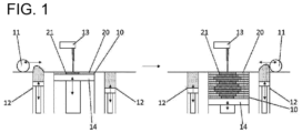
- the additive manufacturing includes melting and solidifying the powder material by laser light irradiation.
- additive manufacturing is performed by a powder bed fusion method using laser light as irradiation energy.
- the additive manufacturing is performed by the SLM method.
- a titanium carbide (TiC) powder having an average particle size (D 50 ) of about 1 um and a cobalt (Co) powder having an average particle size (D 50 ) of about 3 um were prepared.
- Carboxymethyl cellulose (CMC) was prepared as a binder.
- a TiC powder and a Co powder were mixed such that the Co powder accounted for 39 mass% (26.4 volume%) of the total amount of the TiC powder and the Co powder.
- 99 parts by mass of a mixture of the TiC powder and the Co powder and 1 part by mass of CMC were blended, and the resulting blended powder was wet-mixed, and then granulated with a spray dryer.
- the obtained granulated particles were sintered to manufacture a powder material formed of the granulated sintered particles (secondary particles) according to the present Example.
- the melting point of TiC is 3250°C, the standard enthalpy of formation of TiC is -185 kJ/mol, and the solid solubility of TiC in Co at 1250°C is 1 mass%.
- the melting point of the carbide ceramic a value described in Superhard Alloys and Sintered Hard Materials: Fundamentals and Applications, edited by Hisashi Suzuki, Maruzen Publishing Co., Ltd. (February 1986 ) can be used.
- the standard enthalpy of formation of the carbide ceramic a value described in Kagaku Binran, Kiso Hen, 5th edition, edited by The Chemical Society of Japan, Maruzen Publishing Co., Ltd. (February 2004 ) can be used.
- the solid solubility value of the carbide ceramic in the metal at 1250°C the value described in F. W. Glaser: Met. Progr., 67 (1955) 77-82 is used.
- a vanadium carbide (VC) powder having an average particle size (D 50 ) of about 0.2 um and a cobalt (Co) powder having an average particle size (D 50 ) of about 3 um were prepared.
- CMC was prepared as a binder.
- a VC powder and a Co powder were mixed such that the Co powder accounted for 36 mass% (26.4 volume%) of the total amount of the VC powder and the Co powder. Then, 99 parts by mass of a mixture of the VC powder and the Co powder and 1 part by mass of CMC were blended.
- the powder material according to the present Example was manufactured by the same process as in Example 1 except for the above.
- the melting point of VC is 2830°C
- the standard enthalpy of formation of VC is -102 kJ/mol
- the solid solubility of VC in Co at 1250°C is 6 mass%.
- a zirconium carbide (ZrC) powder having an average particle size (D 50 ) of about 5 um and a cobalt (Co) powder having an average particle size (D 50 ) of about 3 um were prepared.
- CMC was prepared as a binder.
- a ZrC powder and a Co powder were mixed such that the Co powder accounted for 32 mass% (26.4 volume%) of the total amount of the ZrC powder and the Co powder.
- 99 parts by mass of a mixture of ZrC powder and Co powder and 1 part by mass of CMC were blended.
- the powder material according to the present Example was manufactured by the same process as in Example 1 except for the above.
- the melting point of ZrC is 3180°C, and the standard enthalpy of formation of ZrC is -203 kJ/mol.
- a niobium carbide (NbC) powder having an average particle size (D 50 ) of about 2 um and a cobalt (Co) powder having an average particle size (D 50 ) of about 3 um were prepared.
- CMC was prepared as a binder.
- a NbC powder and a Co powder were mixed such that the Co powder accounted for 29 mass% (26.4 volume%) of the total amount of the NbC powder and the Co powder. Then, 99 parts by mass of a mixture of the NbC powder and the Co powder and 1 part by mass of CMC were blended.
- the powder material according to the present Example was manufactured by the same process as in Example 1 except for the above.
- the melting point of NbC is 3500°C, the standard enthalpy of formation of NbC is -139 kJ/mol, and the solid solubility of NbC in Co at 1250°C is 5 mass%.
- a tantalum carbide (TaC) powder having an average particle size (D 50 ) of about 1.5 um and a cobalt (Co) powder having an average particle size (D 50 ) of about 3 um were prepared.
- CMC was prepared as a binder.
- a TaC powder and a Co powder were mixed such that the Co powder accounted for 18 mass% (26.4 volume%) of the total amount of the TaC powder and the Co powder. Then, 99 parts by mass of a mixture of the TaC powder and the Co powder and 1 part by mass of CMC were blended.
- the powder material according to the present Example was manufactured by the same process as in Example 1 except for the above.
- the melting point of TaC is 3880°C
- the standard enthalpy of formation of TaC is -146 kJ/mol
- the solid solubility of TaC in Co at 1250°C is 3 mass%.
- a titanium carbide (TiC) powder having an average particle size (D 50 ) of about 1 um and a nickel (Ni) powder having an average particle size (D 50 ) of about 3 um were prepared.
- CMC was prepared as a binder.
- a TiC powder and a Ni powder were mixed such that the Ni powder accounted for 30 mass% (19.2 volume%) of the total amount of the TiC powder and the Ni powder.
- 99 parts by mass of a mixture of the TiC powder and the Ni powder and 1 part by mass of CMC were blended, and the resulting blended powder was wet-mixed, and then granulated with a spray dryer.
- the obtained granulated particles were sintered to manufacture a powder material formed of the granulated sintered particles (secondary particles) according to the present Example.
- the solid solubility of TiC in Ni at 1250°C is 5 mass%.
- a chromium carbide (Cr 3 C 2 ) powder having an average particle size (D 50 ) of about 2 um and a cobalt (Co) powder having an average particle size (D 50 ) of about 3 um were prepared.
- CMC was prepared as a binder.
- a Cr 3 C 2 powder and a Co powder were mixed such that the Co powder accounted for 32 mass% (26.4 volume%) of the total amount of the Cr 3 C 2 powder and the Co powder. Then, 99 parts by mass of a mixture of the Cr 3 C 2 powder and the Co powder and 1 part by mass of CMC were blended.
- the powder material according to the present Comparative Example was manufactured by the same process as in Example 1 except for the above.
- the melting point of Cr 3 C 2 is 1895°C
- the standard enthalpy of formation of Cr 3 C 2 is -81 kJ/mol
- the solid solubility of Cr 3 C 2 in Co at 1250°C is 12 mass%.
- a molybdenum carbide (Mo 2 C) powder having an average particle size (D 50 ) of about 2 um and a cobalt (Co) powder having an average particle size (D 50 ) of about 3 um were prepared.
- CMC was prepared as a binder.
- a Mo 2 C powder and a Co powder were mixed such that the Co powder accounted for 26 mass% (26.4 volume%) of the total amount of the Mo 2 C powder and the Co powder. Then, 99 parts by mass of a mixture of the Mo 2 C powder and the Co powder and 1 part by mass of CMC were blended.
- the powder material according to the present Comparative Example was manufactured by the same process as in Example 1 except for the above.
- the melting point of Mo 2 C is 2690°C
- the standard enthalpy of formation of Mo 2 C is -25 kJ/mol
- the solid solubility of Mo 2 C in Co at 1250°C is 13 mass%.
- a tungsten carbide (WC) powder having an average particle size (D 50 ) of about 2 um and a cobalt (Co) powder having an average particle size (D 50 ) of about 3 um were prepared.
- CMC was prepared as a binder.
- a WC powder and a Co powder were mixed such that the Co powder accounted for 17 mass% (26.4 volume%) of the e total amount of the WC powder and the Co powder. Then, 99 parts by mass of a mixture of the WC powder and the Co powder and 1 part by mass of CMC were blended.
- the powder material according to the present Comparative Example was manufactured by the same process as in Example 1 except for the above.
- the melting point of WC is 2600°C
- the standard enthalpy of formation of WC is -41 kJ/mol
- the solid solubility of WC in Co at 1250°C is 22 mass%.
- the average particle size (average particle size of primary particles) of the raw material powder the particle size at 50% of the integrated value in the volume-based particle size distribution measured by a particle size distribution measuring device based on the laser diffraction/scattering method (50% volume average particle size, D 50 ) was adopted.
- a value calculated as the diameter of spherical particles (sphere equivalent diameter) calculated from the specific surface area was adopted.
- the specific surface area can be, for example, a value calculated by the BET method from the gas adsorption amount of N 2 or the like measured by the continuous flow method using a specific surface area measuring device (FlowSorbII 2300 manufactured by Micromeritics Instrument Corporation).
- the specific surface area can be measured according to "Method for measuring specific surface area of powder (solid) by gas adsorption" defined in JIS Z8830:2013 (ISO9277:2010).
- a volume-based particle size distribution was measured by a commercially available particle size distribution measuring device based on a laser diffraction/scattering method.
- D 3 , D 50 , and D 97 in the corresponding columns in Table 1 values of a cumulative 3% particle size, a cumulative 50% particle size (average particle size), and a cumulative 97% particle size from the small particle size side based on the obtained particle size distribution are shown, respectively.
- the average particle size (D 50 ) of the powder materials prepared in each of Examples and Comparative Examples was in the range of 25 to 30 um, and it was found that most of the particles were present in the range of 10 to 60 ⁇ m.
- the granule strength of the powder material (granulated sintered particles) prepared in each of Examples and Comparative Examples was measured using an electromagnetic force loading type compression testing machine. Specifically, 10 or more granulated sintered particles constituting the powder material of each of Examples and Comparative Examples were randomly sampled, and the arithmetic average value of the fracture strength measured using a commercially available micro compression testing device (MCT-500: manufactured by Shimadzu Corporation) was taken as the granule strength (kgf/mm 2 ).
- the granule strengths (kgf/mm 2 ) of the powder materials of each of Examples and Comparative Examples are shown in corresponding columns of Table 1.
- the bulk density of the powder material (granulated sintered particles) prepared in each of Examples and Comparative Examples was measured.
- a value measured in accordance with a metal powder-apparent density measurement method defined in JIS Z2504:2012 was adopted. Specifically, the bulk density was calculated by measuring the mass of the powder when a container having a predetermined volume was filled in a naturally filled state with the powder naturally flowing out from an orifice having a diameter of 2.5 mm.
- a value measured using a JIS cassette densitometer for metal powders manufactured by Tsutsui Scientific Instruments Co., Ltd.
- the repose angle of the powder material (granulated sintered particles) prepared in each of Examples and Comparative Examples was measured.
- the repose angle means a bottom angle calculated from a diameter and a height of a conical deposit generated by dropping a powder material from a funnel having a certain height onto a horizontal substrate.
- the repose angle was measured according to the provision of JIS R 9301-2-2:1999 "Alumina powder physical property measurement method-2: repose angle". The results are shown in Table 1 below.
- a simple cube-shaped additive-manufactured product was prepared using a commercially available additive manufacturing apparatus (product name: ProX DMP200, manufactured by 3D Systems Corporation) using the powder material (granulated sintered particles) prepared in each of Examples and Comparative Examples. That is, the powder material laid flat was irradiated with laser light and melted layer by layer, and this process was repeated to prepare a cube-shaped additive-manufactured product (30 mm long ⁇ 10 mm wide ⁇ 10 mm thick).
- the laser light had an output of 300 W, a scanning speed of 300 mm/s, a pitch width of 0.1 mm, a layering thickness per layer of 30 um, and the number of layers was 334.
- the obtained additive-manufactured product was subjected to heat treatment. That is, the firing treatment was performed in a reduced-pressure atmosphere (10 Pa) at 1320°C for 4 hours (continuous).
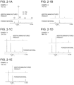
- the powder materials obtained in each of Examples and Comparative Examples were subjected to X-ray diffraction (XRD) measurement using CuK ⁇ rays before and after being irradiated with laser light. That is, XRD measurement was performed on a powder material (granulated sintered particles) before being irradiated with laser light and an additive-manufactured product after being irradiated with laser light (specifically, after additive manufacturing including laser light irradiation) and before being subjected to heat treatment.
- XRD X-ray diffraction
- 2-2F to 2-2H show XRD spectra of the powder materials obtained in Examples 1 to 5 and Comparative Examples 1 to 3 before and after being irradiated with laser light.
- "powder material” represents an XRD spectrum of a powder material prepared in each of Examples and Comparative Examples
- additive-manufactured product represents an XRD spectrum of an additive-manufactured product prepared by additive manufacturing including laser light irradiation using the powder material.
- the peaks of the XRD spectrum after laser light irradiation when the corresponding peaks were observed in the spectrum before laser light irradiation, the peaks were determined to be peaks derived from the powder material.
- the peaks of the XRD spectrum after laser light irradiation when corresponding peaks were not observed in the spectrum before laser light irradiation, the peaks were determined to be peaks other than peaks derived from the powder material.
- the strength of the peaks other than the peaks derived from the powder material was less than 1% of the strength of the peak having the highest intensity in the XRD spectrum after laser light irradiation, the peaks other than the peaks derived from the powder material were evaluated as "absent", and when the strength was 1% or more, the peaks were evaluated as "present".
- the XRD spectrum of the sintered body after being subjected to the heat treatment was measured in the same manner, and no peaks other than the peaks derived from the powder material were observed in any sintered body.
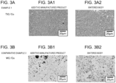
- the additive-manufactured product obtained in Example 1 and the sintered body obtained by heat-treating the additive-manufactured product were each cut in a direction orthogonal to the layering direction, and the cross section was observed at a magnification of 1000 using a scanning electron microscope (SEM, S-3000N manufactured by Hitachi High-Technologies Corporation).
- SEM scanning electron microscope
- the observation of the cross section of the additive-manufactured product in the present specification was performed by embedding a sample for evaluation of the additive-manufactured product in a resin and exposing the cross-section according to a standard method.
- FIGS. 3A1, and 3A2 are SEM photographs of cross sections of an additive-manufactured product obtained in Example 1 and a sintered body obtained by heat-treating the additive-manufactured product, respectively.
- a black region is a region where TiC exists
- a white region is a region where Co exists.
- FIGS. 3B1, and 3B2 are SEM photographs of cross sections of an additive-manufactured product obtained in Comparative Example 3 and a sintered body obtained by heat-treating the additive-manufactured product, respectively.
- a black region is a region where Co exists
- a white region is a region where WC exists.
- a cross section of the sintered body after heat treatment of the additive-manufactured product prepared in each of Examples and Comparative Examples was mirror-polished, and the Vickers hardness in such a cross section was measured in accordance with JIS Z2244:2009.
- the Vickers hardness was calculated from an indentation obtained when a diamond indenter having a facing angle of 136° was pressed under a test force of 0.2 kgf (1.96 N) and a retention time of 10 seconds using a hard microhardness testing device (HMV-1 manufactured by Shimadzu Corporation).
- the Vickers hardness was measured at six points, and the arithmetic average value thereof was taken as the hardness (Vickers hardness (HV)) of the additive-manufactured product (sintered body) after the heat treatment.
- HV the hardness of the additive-manufactured product
- the additive-manufactured product prepared in Example 6 did not show any peaks other than the peaks derived from the powder material before laser light irradiation in the XRD spectrum (not shown). Further, in the powder materials of Examples 1, 2, and 4 to 6, the solid solubility of carbide ceramic in the metal at 1250°C was 8 mass% or less. In the additive-manufactured product using such a powder material, for example, as shown in FIG. 3A1 , a homogeneous and dense additive-manufactured product in which cracks and chips were not recognized even when heat treatment was not performed was obtained. Furthermore, no noticeable particle growth was observed even when the heat treatment was performed as in FIG. 3A2 . As shown in Table 1, it was found that the additive-manufactured product (sintered body) after the heat treatment exhibited excellent hardness.
- the additive-manufactured products prepared in Comparative Examples 1 to 3 show peaks other than the peaks derived from the powder material before the laser light irradiation in the XRD spectrum as shown by the arrows in FIGS. 2-2F to 2-2H . This is considered to indicate that a brittle phase is formed in the alloy structure of the carbide ceramic and the metal.
- peaks derived from Co 3 W 3 C which is a reaction product of WC and Co
- peaks derived from W 2 C which is a product in which carbon in WC is reduced, are observed.
- peaks are not observed the XRD spectrum of the powder material, and can be said to be peaks other than peaks derived from the powder material.
- a brittle phase such as an ⁇ phase is generated by the above-described reaction product and product.
- peaks considered to be derived from a product in which carbon in Cr 3 C 2 is reduced is observed at a position indicated by the arrows.
- a peak considered to be derived from a reaction product of Mo 2 C and Co is observed at a position indicated by an arrow.
- the solid solubility of the carbide ceramic in the metal at 1250°C was more than 8 mass%.
- a dense additive-manufactured product was not obtained as in FIG. 3B1 .
- the hardness was insufficient in the additive-manufactured product (sintered body) after the heat treatment.
Landscapes
- Chemical & Material Sciences (AREA)
- Engineering & Computer Science (AREA)
- Materials Engineering (AREA)
- Manufacturing & Machinery (AREA)
- Mechanical Engineering (AREA)
- Metallurgy (AREA)
- Organic Chemistry (AREA)
- Physics & Mathematics (AREA)
- Plasma & Fusion (AREA)
- Carbon And Carbon Compounds (AREA)
- Powder Metallurgy (AREA)
Applications Claiming Priority (1)
| Application Number | Priority Date | Filing Date | Title |
|---|---|---|---|
| JP2023170499A JP2025060020A (ja) | 2023-09-29 | 2023-09-29 | 積層造形用粉末材料および該粉末材料を用いた造形物の製造方法 |
Publications (1)
| Publication Number | Publication Date |
|---|---|
| EP4530003A1 true EP4530003A1 (fr) | 2025-04-02 |
Family
ID=92926284
Family Applications (1)
| Application Number | Title | Priority Date | Filing Date |
|---|---|---|---|
| EP24203281.1A Pending EP4530003A1 (fr) | 2023-09-29 | 2024-09-27 | Matériau en poudre pour fabrication additive et procédé de fabrication de produit fabriqué de manière additive à l'aide d'un matériau en poudre |
Country Status (3)
| Country | Link |
|---|---|
| US (1) | US20250108435A1 (fr) |
| EP (1) | EP4530003A1 (fr) |
| JP (1) | JP2025060020A (fr) |
Citations (9)
| Publication number | Priority date | Publication date | Assignee | Title |
|---|---|---|---|---|
| WO2015194678A1 (fr) | 2014-06-20 | 2015-12-23 | 株式会社フジミインコーポレーテッド | Matériau en poudre destiné à être utilisé en modelage de poudre en strates et procédé de modelage de poudre en strates l'utilisant |
| JP2017113952A (ja) | 2015-12-22 | 2017-06-29 | 株式会社フジミインコーポレーテッド | 粉末積層造形に用いるための造形用材料 |
| JP2017115194A (ja) | 2015-12-22 | 2017-06-29 | 株式会社フジミインコーポレーテッド | 粉末積層造形に用いるための造形用材料 |
| JP2017114716A (ja) | 2015-12-22 | 2017-06-29 | 株式会社フジミインコーポレーテッド | 粉末積層造形に用いるための造形用材料 |
| US20200392607A1 (en) * | 2019-06-12 | 2020-12-17 | C4 Carbides Limited | Carbide material for cutting devices and associated method of manufacture |
| CN114433837A (zh) * | 2022-01-27 | 2022-05-06 | 恒普(宁波)激光科技有限公司 | 一种异质相界面强化方法及产品 |
| CN114959396B (zh) * | 2022-04-22 | 2023-07-04 | 哈尔滨工程大学 | 一种点阵晶格结构的TiC/Mo合金及其选区激光熔化制备方法 |
| US20230226612A1 (en) * | 2020-03-12 | 2023-07-20 | Kabushiki Kaisha Kobe Seiko Sho (Kobe Steel, Ltd.) | Method for manufacturing additively manufactured article, and additively manufactured article |
| JP2023170499A (ja) | 2022-05-19 | 2023-12-01 | 三菱鉛筆株式会社 | 筆記具用インク収容部材 |
-
2023
- 2023-09-29 JP JP2023170499A patent/JP2025060020A/ja active Pending
-
2024
- 2024-09-24 US US18/894,619 patent/US20250108435A1/en active Pending
- 2024-09-27 EP EP24203281.1A patent/EP4530003A1/fr active Pending
Patent Citations (9)
| Publication number | Priority date | Publication date | Assignee | Title |
|---|---|---|---|---|
| WO2015194678A1 (fr) | 2014-06-20 | 2015-12-23 | 株式会社フジミインコーポレーテッド | Matériau en poudre destiné à être utilisé en modelage de poudre en strates et procédé de modelage de poudre en strates l'utilisant |
| JP2017113952A (ja) | 2015-12-22 | 2017-06-29 | 株式会社フジミインコーポレーテッド | 粉末積層造形に用いるための造形用材料 |
| JP2017115194A (ja) | 2015-12-22 | 2017-06-29 | 株式会社フジミインコーポレーテッド | 粉末積層造形に用いるための造形用材料 |
| JP2017114716A (ja) | 2015-12-22 | 2017-06-29 | 株式会社フジミインコーポレーテッド | 粉末積層造形に用いるための造形用材料 |
| US20200392607A1 (en) * | 2019-06-12 | 2020-12-17 | C4 Carbides Limited | Carbide material for cutting devices and associated method of manufacture |
| US20230226612A1 (en) * | 2020-03-12 | 2023-07-20 | Kabushiki Kaisha Kobe Seiko Sho (Kobe Steel, Ltd.) | Method for manufacturing additively manufactured article, and additively manufactured article |
| CN114433837A (zh) * | 2022-01-27 | 2022-05-06 | 恒普(宁波)激光科技有限公司 | 一种异质相界面强化方法及产品 |
| CN114959396B (zh) * | 2022-04-22 | 2023-07-04 | 哈尔滨工程大学 | 一种点阵晶格结构的TiC/Mo合金及其选区激光熔化制备方法 |
| JP2023170499A (ja) | 2022-05-19 | 2023-12-01 | 三菱鉛筆株式会社 | 筆記具用インク収容部材 |
Non-Patent Citations (4)
| Title |
|---|
| F. W. GLASER, MET. PROGR, vol. 67, 1955, pages 77 - 82 |
| F. W. GLASER, MET. PROGR., vol. 67, 1955, pages 77 - 82 |
| KAGAKU BINRANKISO HEN: "The Chemical Society of Japan", February 2004, MARUZEN PUBLISHING CO., LTD. |
| SUPERHARD ALLOYSSINTERED: "Superhard Alloys and Sintered Hard Materials: Fundamentals and Applications", February 1986, MARUZEN PUBLISHING CO., LTD. |
Also Published As
| Publication number | Publication date |
|---|---|
| JP2025060020A (ja) | 2025-04-10 |
| US20250108435A1 (en) | 2025-04-03 |
Similar Documents
| Publication | Publication Date | Title |
|---|---|---|
| US20230127550A1 (en) | Additive manufacturing of metal alloys and metal alloy matrix composites | |
| JP7731810B2 (ja) | 反応性付加製造 | |
| EP3395479B1 (fr) | Matériel de fabrication additive pour la fabrication de prototypage rapide de poudre | |
| EP3395782B1 (fr) | Fabrication de prototypage rapide de poudre | |
| EP3159141B1 (fr) | Matériau en poudre | |
| EP3395781B1 (fr) | Matériel de fabrication additive pour la fabrication de prototypage rapide de poudre | |
| US10946445B2 (en) | Method of manufacturing a cemented carbide material | |
| JP7730682B2 (ja) | 銅基粉、その製造方法、および銅基粉を用いた光造形物の製造方法 | |
| US11739396B2 (en) | Powder material and method for manufacturing molded article | |
| EP4530003A1 (fr) | Matériau en poudre pour fabrication additive et procédé de fabrication de produit fabriqué de manière additive à l'aide d'un matériau en poudre | |
| Song et al. | Sintering properties of in situ Ti-TiB microlattices created by 3D extrusion printing of TiH2+ TiB2 inks | |
| JP7336944B2 (ja) | 造形物の製造方法 | |
| Xiong et al. | (Ti, W) C–Ni cermets by laser engineered net shaping | |
| RU2184644C2 (ru) | Алмазосодержащий слоистый композит и способ его получения | |
| EP4317502A1 (fr) | Matériau en poudre pour formage en couche par couche et procédé de fabrication d'un produit formé à l'aide d'un matériau en poudre | |
| Shearwood et al. | Spark plasma sintering of wire exploded tungsten nano-powder | |
| Verduzco et al. | Synthesis of Copper Based Composites Reinforced with (Ni, Cu) 3Al Intermetallic via Low Energy Ball Milling | |
| WO2004096469A1 (fr) | Composition de poudres metalliques | |
| EP4596734A1 (fr) | Matériau en poudre pour fabrication additive et procédé de production dudit matériau en poudre | |
| JP2020012149A (ja) | 三次元造形物の製造方法と三次元造形システム | |
| Kumar et al. | Effect of process parameters and VC content on structural and mechanical properties of WC-20Co nano composites. | |
| Ajjarapu | Sintering Behavior of Ni/TiC Cermet Scaffolds Fabricated via Particle-Based Ink Extrusion 3D Printing | |
| CA3268333A1 (fr) | Mélange granulaire pour fabrication additive | |
| IL320026A (en) | Granular mixture for additive manufacturing |
Legal Events
| Date | Code | Title | Description |
|---|---|---|---|
| PUAI | Public reference made under article 153(3) epc to a published international application that has entered the european phase |
Free format text: ORIGINAL CODE: 0009012 |
|
| STAA | Information on the status of an ep patent application or granted ep patent |
Free format text: STATUS: THE APPLICATION HAS BEEN PUBLISHED |
|
| AK | Designated contracting states |
Kind code of ref document: A1 Designated state(s): AL AT BE BG CH CY CZ DE DK EE ES FI FR GB GR HR HU IE IS IT LI LT LU LV MC ME MK MT NL NO PL PT RO RS SE SI SK SM TR |
|
| STAA | Information on the status of an ep patent application or granted ep patent |
Free format text: STATUS: REQUEST FOR EXAMINATION WAS MADE |
|
| 17P | Request for examination filed |
Effective date: 20251002 |