EP4530123A1 - Dispositif de charge pour véhicule électrique et procédé de charge de véhicule électrique - Google Patents
Dispositif de charge pour véhicule électrique et procédé de charge de véhicule électrique Download PDFInfo
- Publication number
- EP4530123A1 EP4530123A1 EP24199233.8A EP24199233A EP4530123A1 EP 4530123 A1 EP4530123 A1 EP 4530123A1 EP 24199233 A EP24199233 A EP 24199233A EP 4530123 A1 EP4530123 A1 EP 4530123A1
- Authority
- EP
- European Patent Office
- Prior art keywords
- current
- charging
- charging device
- series
- current measurement
- Prior art date
- Legal status (The legal status is an assumption and is not a legal conclusion. Google has not performed a legal analysis and makes no representation as to the accuracy of the status listed.)
- Pending
Links
Images


Classifications
-
- B—PERFORMING OPERATIONS; TRANSPORTING
- B60—VEHICLES IN GENERAL
- B60L—PROPULSION OF ELECTRICALLY-PROPELLED VEHICLES; SUPPLYING ELECTRIC POWER FOR AUXILIARY EQUIPMENT OF ELECTRICALLY-PROPELLED VEHICLES; ELECTRODYNAMIC BRAKE SYSTEMS FOR VEHICLES IN GENERAL; MAGNETIC SUSPENSION OR LEVITATION FOR VEHICLES; MONITORING OPERATING VARIABLES OF ELECTRICALLY-PROPELLED VEHICLES; ELECTRIC SAFETY DEVICES FOR ELECTRICALLY-PROPELLED VEHICLES
- B60L53/00—Methods of charging batteries, specially adapted for electric vehicles; Charging stations or on-board charging equipment therefor; Exchange of energy storage elements in electric vehicles
- B60L53/60—Monitoring or controlling charging stations
- B60L53/62—Monitoring or controlling charging stations in response to charging parameters, e.g. current, voltage or electrical charge
-
- B—PERFORMING OPERATIONS; TRANSPORTING
- B60—VEHICLES IN GENERAL
- B60L—PROPULSION OF ELECTRICALLY-PROPELLED VEHICLES; SUPPLYING ELECTRIC POWER FOR AUXILIARY EQUIPMENT OF ELECTRICALLY-PROPELLED VEHICLES; ELECTRODYNAMIC BRAKE SYSTEMS FOR VEHICLES IN GENERAL; MAGNETIC SUSPENSION OR LEVITATION FOR VEHICLES; MONITORING OPERATING VARIABLES OF ELECTRICALLY-PROPELLED VEHICLES; ELECTRIC SAFETY DEVICES FOR ELECTRICALLY-PROPELLED VEHICLES
- B60L53/00—Methods of charging batteries, specially adapted for electric vehicles; Charging stations or on-board charging equipment therefor; Exchange of energy storage elements in electric vehicles
- B60L53/10—Methods of charging batteries, specially adapted for electric vehicles; Charging stations or on-board charging equipment therefor; Exchange of energy storage elements in electric vehicles characterised by the energy transfer between the charging station and the vehicle
- B60L53/14—Conductive energy transfer
- B60L53/16—Connectors, e.g. plugs or sockets, specially adapted for charging electric vehicles
-
- B—PERFORMING OPERATIONS; TRANSPORTING
- B60—VEHICLES IN GENERAL
- B60L—PROPULSION OF ELECTRICALLY-PROPELLED VEHICLES; SUPPLYING ELECTRIC POWER FOR AUXILIARY EQUIPMENT OF ELECTRICALLY-PROPELLED VEHICLES; ELECTRODYNAMIC BRAKE SYSTEMS FOR VEHICLES IN GENERAL; MAGNETIC SUSPENSION OR LEVITATION FOR VEHICLES; MONITORING OPERATING VARIABLES OF ELECTRICALLY-PROPELLED VEHICLES; ELECTRIC SAFETY DEVICES FOR ELECTRICALLY-PROPELLED VEHICLES
- B60L53/00—Methods of charging batteries, specially adapted for electric vehicles; Charging stations or on-board charging equipment therefor; Exchange of energy storage elements in electric vehicles
- B60L53/20—Methods of charging batteries, specially adapted for electric vehicles; Charging stations or on-board charging equipment therefor; Exchange of energy storage elements in electric vehicles characterised by converters located in the vehicle
- B60L53/22—Constructional details or arrangements of charging converters specially adapted for charging electric vehicles
-
- G—PHYSICS
- G01—MEASURING; TESTING
- G01R—MEASURING ELECTRIC VARIABLES; MEASURING MAGNETIC VARIABLES
- G01R31/00—Arrangements for testing electric properties; Arrangements for locating electric faults; Arrangements for electrical testing characterised by what is being tested not provided for elsewhere
- G01R31/12—Testing dielectric strength or breakdown voltage ; Testing or monitoring effectiveness or level of insulation, e.g. of a cable or of an apparatus, for example using partial discharge measurements; Electrostatic testing
- G01R31/1227—Testing dielectric strength or breakdown voltage ; Testing or monitoring effectiveness or level of insulation, e.g. of a cable or of an apparatus, for example using partial discharge measurements; Electrostatic testing of components, parts or materials
-
- H—ELECTRICITY
- H02—GENERATION; CONVERSION OR DISTRIBUTION OF ELECTRIC POWER
- H02H—EMERGENCY PROTECTIVE CIRCUIT ARRANGEMENTS
- H02H1/00—Details of emergency protective circuit arrangements
- H02H1/0007—Details of emergency protective circuit arrangements concerning the detecting means
- H02H1/0015—Using arc detectors
-
- H—ELECTRICITY
- H02—GENERATION; CONVERSION OR DISTRIBUTION OF ELECTRIC POWER
- H02J—ELECTRIC POWER NETWORKS; CIRCUIT ARRANGEMENTS OR SYSTEMS FOR SUPPLYING OR DISTRIBUTING ELECTRIC POWER; SYSTEMS FOR STORING ELECTRIC ENERGY
- H02J7/00—Circuit arrangements for charging or discharging batteries or for supplying loads from batteries
- H02J7/70—Circuit arrangements for charging or discharging batteries or for supplying loads from batteries characterised by the mechanical construction
-
- H—ELECTRICITY
- H02—GENERATION; CONVERSION OR DISTRIBUTION OF ELECTRIC POWER
- H02J—ELECTRIC POWER NETWORKS; CIRCUIT ARRANGEMENTS OR SYSTEMS FOR SUPPLYING OR DISTRIBUTING ELECTRIC POWER; SYSTEMS FOR STORING ELECTRIC ENERGY
- H02J7/00—Circuit arrangements for charging or discharging batteries or for supplying loads from batteries
- H02J7/90—Regulation of charging or discharging current or voltage
- H02J7/933—Regulation of charging or discharging current or voltage the cycle being controlled or terminated in response to electric parameters
-
- G—PHYSICS
- G01—MEASURING; TESTING
- G01R—MEASURING ELECTRIC VARIABLES; MEASURING MAGNETIC VARIABLES
- G01R19/00—Arrangements for measuring currents or voltages or for indicating presence or sign thereof
- G01R19/165—Indicating that current or voltage is either above or below a predetermined value or within or outside a predetermined range of values
-
- G—PHYSICS
- G01—MEASURING; TESTING
- G01R—MEASURING ELECTRIC VARIABLES; MEASURING MAGNETIC VARIABLES
- G01R31/00—Arrangements for testing electric properties; Arrangements for locating electric faults; Arrangements for electrical testing characterised by what is being tested not provided for elsewhere
- G01R31/50—Testing of electric apparatus, lines, cables or components for short-circuits, continuity, leakage current or incorrect line connections
- G01R31/66—Testing of connections, e.g. of plugs or non-disconnectable joints
- G01R31/68—Testing of releasable connections, e.g. of terminals mounted on a printed circuit board
- G01R31/69—Testing of releasable connections, e.g. of terminals mounted on a printed circuit board of terminals at the end of a cable or a wire harness; of plugs; of sockets, e.g. wall sockets or power sockets in appliances
-
- H—ELECTRICITY
- H02—GENERATION; CONVERSION OR DISTRIBUTION OF ELECTRIC POWER
- H02H—EMERGENCY PROTECTIVE CIRCUIT ARRANGEMENTS
- H02H7/00—Emergency protective circuit arrangements specially adapted for specific types of electric machines or apparatus or for sectionalised protection of cable or line systems, and effecting automatic switching in the event of an undesired change from normal working conditions
- H02H7/26—Sectionalised protection of cable or line systems, e.g. for disconnecting a section on which a short-circuit, earth fault, or arc discharge has occured
-
- H—ELECTRICITY
- H02—GENERATION; CONVERSION OR DISTRIBUTION OF ELECTRIC POWER
- H02J—ELECTRIC POWER NETWORKS; CIRCUIT ARRANGEMENTS OR SYSTEMS FOR SUPPLYING OR DISTRIBUTING ELECTRIC POWER; SYSTEMS FOR STORING ELECTRIC ENERGY
- H02J2207/00—Details of circuit arrangements for charging or discharging batteries or supplying loads from batteries
- H02J2207/20—Charging or discharging characterised by the power electronics converter
-
- Y—GENERAL TAGGING OF NEW TECHNOLOGICAL DEVELOPMENTS; GENERAL TAGGING OF CROSS-SECTIONAL TECHNOLOGIES SPANNING OVER SEVERAL SECTIONS OF THE IPC; TECHNICAL SUBJECTS COVERED BY FORMER USPC CROSS-REFERENCE ART COLLECTIONS [XRACs] AND DIGESTS
- Y02—TECHNOLOGIES OR APPLICATIONS FOR MITIGATION OR ADAPTATION AGAINST CLIMATE CHANGE
- Y02T—CLIMATE CHANGE MITIGATION TECHNOLOGIES RELATED TO TRANSPORTATION
- Y02T10/00—Road transport of goods or passengers
- Y02T10/60—Other road transportation technologies with climate change mitigation effect
- Y02T10/70—Energy storage systems for electromobility, e.g. batteries
-
- Y—GENERAL TAGGING OF NEW TECHNOLOGICAL DEVELOPMENTS; GENERAL TAGGING OF CROSS-SECTIONAL TECHNOLOGIES SPANNING OVER SEVERAL SECTIONS OF THE IPC; TECHNICAL SUBJECTS COVERED BY FORMER USPC CROSS-REFERENCE ART COLLECTIONS [XRACs] AND DIGESTS
- Y02—TECHNOLOGIES OR APPLICATIONS FOR MITIGATION OR ADAPTATION AGAINST CLIMATE CHANGE
- Y02T—CLIMATE CHANGE MITIGATION TECHNOLOGIES RELATED TO TRANSPORTATION
- Y02T10/00—Road transport of goods or passengers
- Y02T10/60—Other road transportation technologies with climate change mitigation effect
- Y02T10/7072—Electromobility specific charging systems or methods for batteries, ultracapacitors, supercapacitors or double-layer capacitors
-
- Y—GENERAL TAGGING OF NEW TECHNOLOGICAL DEVELOPMENTS; GENERAL TAGGING OF CROSS-SECTIONAL TECHNOLOGIES SPANNING OVER SEVERAL SECTIONS OF THE IPC; TECHNICAL SUBJECTS COVERED BY FORMER USPC CROSS-REFERENCE ART COLLECTIONS [XRACs] AND DIGESTS
- Y02—TECHNOLOGIES OR APPLICATIONS FOR MITIGATION OR ADAPTATION AGAINST CLIMATE CHANGE
- Y02T—CLIMATE CHANGE MITIGATION TECHNOLOGIES RELATED TO TRANSPORTATION
- Y02T90/00—Enabling technologies or technologies with a potential or indirect contribution to GHG emissions mitigation
- Y02T90/10—Technologies relating to charging of electric vehicles
- Y02T90/14—Plug-in electric vehicles
Definitions
- the invention relates to a charging device for an electric vehicle and a method for charging an electric vehicle.
- motor vehicles are becoming increasingly electrified.
- Such electric vehicles require regular charging via charging devices.
- the electric vehicle is typically connected to the charging device via a plug connection.
- a charging socket is located on the electric vehicle, which is designed to accept a charging plug from the charging device.
- the charging device is a high-power electrical device. Personal injury and property damage during and as a result of the operation of the charging device should be avoided.
- the invention solves this problem by the charging device of claim 1 and the method of claim 11. Preferred embodiments of the invention are specified in the subclaims.
- a first aspect of the invention relates to a charging device for an electric vehicle.
- the charging device comprises at least one charging plug, a power converter connected to the charging plug and a supply connection of the charging device, a current sensor connected between the power converter and the charging plug, a switch, and a control unit.
- the charging plug is designed to be connected to the electric vehicle.
- the power converter is connected to the charging plug and a supply connection of the charging device and is designed to receive electrical energy from the supply connection and to output it to the charging plug in accordance with a request from the electric vehicle.
- the current sensor is connected between the power converter and the charging plug and is designed to measure a current flowing between the power converter and the charging plug and to output it as a measured current value.
- the switch is designed to switch off the current flowing from the power converter to the charging plug.
- the control unit is connected to the current sensor and the switch. According to the invention, the control unit is designed to detect an arcing event based on a series of current measurement values and, upon detection of the arcing event, to control the switch to switch off the current flowing from the power converter to the charging plug.
- the invention is based on and incorporates the finding that an arcing event at the connector between the charging plug and the electric vehicle can be detected using a series of current measurements.
- Such an arcing event can be caused by a loose connection between the charging plug and the charging socket, which in turn can be due to deformation of the charging plug due to improper handling.
- the arcing event leads to local heating, and the resulting temperatures can lead to oxidation of the conductor surface at the location of the arc and, due to the heat conduction of the metal of the conductor also on surrounding insulators such as the cable sheath.
- the electrical resistance increases, which in turn causes an increase in the heat input due to a flowing current.
- the charging device of the invention can detect an arcing event and, if such an arcing event occurs, cause the charging current to be switched off.
- the charging device can emit a maintenance signal so that a control center or the like can initiate maintenance of the charging device, during which, for example, a damaged or undesirably heavily oxidized charging plug can be replaced or repaired.
- the control unit is configured to compare the current measured values of the series of current measured values with a current threshold and to detect the arcing event based on the rate at which the current threshold is exceeded and/or undershot.
- the current threshold can be set depending on the power requirement of the electric vehicle. Particularly during a DC charging process, the charging device and the electric vehicle negotiate the electrical parameters of the charging process, so that a current threshold can be derived from this, for example, by setting the current threshold to 90 percent of the expected charging current or another proportional value.
- the current threshold should be selected so far below the expected charging current that a typical ripple in the charging current due to internal switching operations of the power converter or the electric vehicle does not lead to false detection.
- the current threshold can also be adaptively derived from a moving average of the charging current or selected according to previously known charging profiles.
- Overshoots and undershoots here are understood in particular to mean intersections of the charging current and the current threshold.
- An overshoot of the current threshold is then an event in which the charging current increases from below the current threshold to above the current threshold; a undershoot accordingly is an event in which the charging current falls from above the current threshold to below the current threshold.
- Such events can occasionally occur due to switching operations and the like.
- the flowing current shows constant, random fluctuations with a large fluctuation range, which often occur several times per second. Accordingly, a high rate of overshoots and/or undershoots of the current threshold can be used as an identifying feature of an arcing event.
- the rate of exceedances and/or undershoots of the current threshold is an easy-to-determine criterion that is more meaningful than, for example, determining the periods or time periods in which the charging current is below or above the current threshold.
- the current sensor is preferably designed to measure the charging current at least once per second, preferably at least ten times per second or more.
- An exceedance can be detected by the control unit in particular when a preceding current measurement value in the series of current measurements is less than or equal to the current threshold and a current measurement value immediately following the preceding current measurement value in the series of current measurements is greater than the current threshold. Accordingly, an undershoot can occur in particular when a preceding current measurement value in the series of current measurements is greater than or equal to the current threshold and a current measurement value immediately following the preceding current measurement value in the series of current measurements The subsequent current measurement value is smaller than the current threshold.
- This detection can be implemented particularly easily in a microcontroller or similar program.
- the control unit is preferably configured to detect the arcing event under a first condition, wherein the first condition is met when the series of current measurements exhibits a first number of exceedances and/or undershoots of the current threshold within a first time period.
- the first number can be selected between 20 and 80 exceedances and/or undershoots
- the first time period can be selected between 5 and 20 seconds.
- the control unit can also be configured to detect the arcing event under a second condition, wherein the second condition is met if the series of current measured values exhibits a second number of exceedances and/or undershoots of the current threshold that is different from the first number within a second time period that is different from the first time period.
- the second number could, for example, be selected between 100 and 250 exceedances and/or undershoots, and the second time period could be selected between 20 and 100 seconds.
- the fulfillment of only one of the two conditions causes the control unit to detect the arcing event. This results in particularly fast detection of the arcing event.
- the control unit can only detect the arcing event if both the first condition and the second condition are met. In this case, false detections can be largely avoided.
- the control unit can be configured to increment a counter when the current threshold is exceeded and/or undershot, and to decrement the counter after a predetermined time period has elapsed.
- the control unit is configured to detect the arcing event when the counter reaches a counter threshold. This is a particularly easy-to-implement implementation of the invention.
- the counter threshold is only reached and the arcing event detected if the rate of exceeding and/or undershooting the current threshold over a longer period of time is higher than the rate of counter decrements due to the repeated elapse of the predetermined time period. This procedure creates a "soft" criterion for detecting an arcing event.
- the counter can be decremented by a value of 5 once per second, and the counter threshold can be selected as 300. An arc event is then detected if there are 350 over- and/or under-currents within 10 seconds or 550 over- and/or under-currents within 50 seconds, etc.
- the charging device can be equipped with a filter connected between the current sensor and the control unit.
- the filter is configured to receive current measurements from the current sensor, filter the received current measurements, and output the filtered current measurements to the control unit.
- the filter can, for example, be a high-pass or band-pass filter that is permeable within a frequency band typical for arc events. It is also conceivable to implement the filter as a Schmitt trigger with a switching hysteresis.
- an overshoot can be detected if a preceding current measurement value of the series of current measurements is less than or equal to the current threshold and a current measurement value immediately following the preceding current measurement value of the series of current measurements is greater than the current threshold.
- An undershoot can be detected if a preceding current measurement value of the series of current measurements is greater than or equal to the current threshold and a current measurement value immediately following the preceding current measurement value of the series of current measurements is less than the current threshold.
- the arc event can be detected under a first condition, which can be fulfilled when the series of current measurements exceeds a first number of and/or have undershoots of the current threshold within a first period of time.
- a second condition for detecting the arc event may be provided, which is fulfilled when the series of current measurement values has a second number of exceedances and/or undershoots of the current threshold value that is different from the first number within a second time period that is different from the first time period.
- the first condition and the second condition must be fulfilled.
- a step of incrementing a counter when the current threshold is exceeded and/or undershot, as well as a step of decrementing the counter after a predetermined period of time has elapsed are provided.
- the arcing event is detected when the counter reaches a counter threshold.
- the current sensor may be provided to subject the current measured values by the current sensor to a filtering step and use the filtered current measured values for the arc event detection steps described above.
- a filtering step for example, a switching hysteresis may be applied to the measured current measured values.
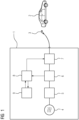
- Fig. 1 shows an embodiment of a charging device 1 according to the invention, wherein the charging device 1 is illustrated in the form of a block diagram.
- the charging device 1 can be connected to an electric vehicle 2 via a charging plug 3 and is itself supplied with power from a supply connection 4, which can be, for example, a three-phase low-voltage mains connection.
- the charging device 1 has a power converter 5, which is supplied with electrical energy via the supply connection 4 and generates a charging current suitable for charging the electric vehicle 2.
- the charging device is preferably designed as a DC charging device to charge the electric vehicle 2 with a direct voltage or a direct current.
- a current sensor 6 and a switch 7 are connected in series between the power converter 5 and the charging plug 3, with the switch 7 being connected downstream of the current sensor 6.
- the current sensor 6 is connected to a control unit 8, which can receive and process current measurements measured by the current sensor 6 and output to the control unit 8.
- the switch 7 can be controlled by the control unit 8. and opened or closed. It serves to disconnect the charging plug 3 when an arcing event is detected by the control unit 8 and, as a result of the detection, the control unit 8 outputs a corresponding control signal to open the switch 7.
- the switch 7 can also be used during normal operation outside of charging processes to electrically disconnect the charging plug 3.
- the control unit 8 is shown connected to a counter 9. However, in most embodiments of the charging device 1 according to the invention, the counter 9 will be implemented as part of the control unit 8 or as a variable of a control program.
- the counter 9 can be incremented or decremented by the control unit 8 during operation. In embodiments of the invention with counter 9, its counter value is compared with a counter threshold to determine whether or not an arcing event has occurred.
- Fig. 2 shows an embodiment of a method according to the invention for charging an electric vehicle 2, which begins with a start step S0 when a charging process for an electric vehicle 2 is started.
- a charging current dimensioned according to a request of the electric vehicle 2 is output.
- the charging current output to the electric vehicle 2 is measured in order to obtain a series of current measurements.
- the series of current measurements is filtered in the subsequent step S3, wherein various filter characteristics, optionally in combination with one another, can be used.
- the filtering serves to increase the reliability of detecting an arc event, but is optional.
- the filtering can be provided to suppress harmonics and fluctuations in the charging current caused by switching operations of the power converter 5.
- step S4 it is checked whether the series of current measurements exceeds and/or falls below a specified current threshold. For example, a current threshold exceedance occurs when the measured current values increase from below the current threshold to above it. A current threshold exceedance occurs when the measured current values decrease from above the current threshold to below it.
- the method can consider both exceedances and undershoots, or just one of the two criteria mentioned.
- step S4 If it is determined in step S4 that an overflow or underflow has occurred, the program branches to step S5, where a counter is incremented. If, however, there was no overflow or underflow, the program continues with step S6, where it checks whether a predetermined period of time has elapsed, in particular whether it has elapsed without an overflow or underflow being detected. If the test in step S6 is positive, the counter is decremented in step S7. Preferably, an underflow of the counter is avoided if the counter has a counter value of zero.
- step S8 After incrementing (step S5) or decrementing (step S7) the counter, a check is made in step S8 to determine whether the counter value has reached a predetermined counter threshold. If this is the case, the charging current has fluctuated in an unexpected and impermissible manner, so that the presence of an arcing event is concluded. Subsequently, in step S9, the charging current is interrupted, which achieves the protective function of the charging plug 3, the charging socket of the electric vehicle 2, generally of the charging device 1, and the surrounding area desired according to the invention. In step S9, an error signal can additionally be output or sent to a remote device such as a remote maintenance center to indicate the need for maintenance. The method according to the invention then ends in step S10. If, however, the check in step S8 has shown that the counter threshold has not been reached, the charging process is continued and branches back to step S2 until the charging process is properly terminated after the desired amount of energy has been released.
- Fig. 3 shows an example transient diagram of the charging current I delivered to an electric vehicle 2.
- the charging current I is plotted against time t, which is measured in seconds, and its magnitude is standardized. Due to the presence of an arcing event, the charging current I exhibits strong fluctuations and temporarily drops to zero, indicating an interim collapse of the arc between charging plug 3 and electric vehicle 2. Not shown, but equally possible, are phases in which the charging current flows undisturbed to the electric vehicle 2 because there is temporarily sufficiently good contact between charging plug 3 and electric vehicle 2.
- the charging current shown is normalized to the current threshold, so that if the value exceeds and/or falls below 1 in the diagram, the counter value is incremented as described above.
- Fig. 4 shows an exemplary transient diagram of a counter value N, as it occurs when executing the method of Fig. 2 and occurrence of a charging current as in Fig. 3
Landscapes
- Engineering & Computer Science (AREA)
- Power Engineering (AREA)
- Transportation (AREA)
- Mechanical Engineering (AREA)
- Physics & Mathematics (AREA)
- General Physics & Mathematics (AREA)
- Charge And Discharge Circuits For Batteries Or The Like (AREA)
Applications Claiming Priority (1)
| Application Number | Priority Date | Filing Date | Title |
|---|---|---|---|
| DE102023209506.8A DE102023209506A1 (de) | 2023-09-28 | 2023-09-28 | Ladevorrichtung für ein Elektrofahrzeug und Verfahren zum Laden eines Elektrofahrzeugs |
Publications (1)
| Publication Number | Publication Date |
|---|---|
| EP4530123A1 true EP4530123A1 (fr) | 2025-04-02 |
Family
ID=92712321
Family Applications (1)
| Application Number | Title | Priority Date | Filing Date |
|---|---|---|---|
| EP24199233.8A Pending EP4530123A1 (fr) | 2023-09-28 | 2024-09-09 | Dispositif de charge pour véhicule électrique et procédé de charge de véhicule électrique |
Country Status (3)
| Country | Link |
|---|---|
| US (1) | US20250108718A1 (fr) |
| EP (1) | EP4530123A1 (fr) |
| DE (1) | DE102023209506A1 (fr) |
Citations (4)
| Publication number | Priority date | Publication date | Assignee | Title |
|---|---|---|---|---|
| EP0506319A2 (fr) * | 1991-03-28 | 1992-09-30 | Eaton Corporation | Arc détecteur capteur de chaos |
| DE102004056436A1 (de) * | 2004-11-19 | 2006-06-01 | Esw-Extel Systems Wedel Gesellschaft Für Ausrüstung Mbh | Verfahren und Vorrichtung zur Erkennung von Fehlerstrom-Lichtbögen in elektrischen Stromkreisen |
| WO2023171880A1 (fr) * | 2022-03-08 | 2023-09-14 | 주식회사 케이에너지시스템 | Appareil de détection d'arc ayant une fonction d'identification de bande multi-fréquence |
| DE102022126466A1 (de) * | 2022-03-14 | 2023-09-14 | GM Global Technology Operations LLC | Systeme zur erfassung von gleichstrom-störlichtbögen in batteriesystem-ladegeräten für elektrofahrzeuge |
Family Cites Families (1)
| Publication number | Priority date | Publication date | Assignee | Title |
|---|---|---|---|---|
| DE102010028626B4 (de) * | 2010-05-05 | 2021-09-16 | Bender Gmbh & Co. Kg | Stromaufladevorrichtung für ein Elektrofahrzeug |
-
2023
- 2023-09-28 DE DE102023209506.8A patent/DE102023209506A1/de active Pending
-
2024
- 2024-09-09 EP EP24199233.8A patent/EP4530123A1/fr active Pending
- 2024-09-30 US US18/901,205 patent/US20250108718A1/en active Pending
Patent Citations (4)
| Publication number | Priority date | Publication date | Assignee | Title |
|---|---|---|---|---|
| EP0506319A2 (fr) * | 1991-03-28 | 1992-09-30 | Eaton Corporation | Arc détecteur capteur de chaos |
| DE102004056436A1 (de) * | 2004-11-19 | 2006-06-01 | Esw-Extel Systems Wedel Gesellschaft Für Ausrüstung Mbh | Verfahren und Vorrichtung zur Erkennung von Fehlerstrom-Lichtbögen in elektrischen Stromkreisen |
| WO2023171880A1 (fr) * | 2022-03-08 | 2023-09-14 | 주식회사 케이에너지시스템 | Appareil de détection d'arc ayant une fonction d'identification de bande multi-fréquence |
| DE102022126466A1 (de) * | 2022-03-14 | 2023-09-14 | GM Global Technology Operations LLC | Systeme zur erfassung von gleichstrom-störlichtbögen in batteriesystem-ladegeräten für elektrofahrzeuge |
Also Published As
| Publication number | Publication date |
|---|---|
| US20250108718A1 (en) | 2025-04-03 |
| DE102023209506A1 (de) | 2025-04-03 |
Similar Documents
| Publication | Publication Date | Title |
|---|---|---|
| DE60015421T2 (de) | Überwachungsanordnung für das Stromversorgungsystem eines Fahrzeugs | |
| DE102016218960B4 (de) | Schalter | |
| DE69414328T2 (de) | Lichtbogenerfassung über die Stromänderung | |
| DE102004056436B4 (de) | Verfahren und Vorrichtung zur Erkennung von Fehlerstrom-Lichtbögen in elektrischen Stromkreisen | |
| EP1915806B1 (fr) | Procédé et dispositif de détection de surcharge pour des outils à main | |
| DE102014005524B4 (de) | Unterbrechung eines Stromes | |
| DE1463453A1 (de) | Elektrisches Steuersystem | |
| EP0993695A1 (fr) | Procede et systeme pour la detection de courts-circuits dans des reseaux basse tension | |
| EP3774434B1 (fr) | Procédé et dispositif pour faire fonctionner un véhicule à moteur | |
| DE102016216401A1 (de) | Verfahren zum Laden eines elektrisch betriebenen Fahrzeuges mit Hilfe eines Ladekabels, Ladekabel und Fehlerstrom-Schutzschaltung zur Detektion eines Gleichstroms | |
| DE4447145B4 (de) | Verfahren und Einrichtung zur Temperaturüberwachung bei Universalmotoren | |
| WO2015078685A1 (fr) | Protection contre les surtensions pour réseau de bord de véhicule automobile en cas de délestage | |
| DE102013223316A1 (de) | Überspannungsschutz für Kraftfahrzeugbordnetz bei Lastabwurf | |
| WO1997020219A2 (fr) | Procede de production de signaux caracterisant des boucles defectueuses dans un reseau d'alimentation electrique polyphase | |
| DE102015201899A1 (de) | Verfahren zur Absicherung eines Hochvolt-Bordnetzes eines Kraftfahrzeugs mit einer ersten und einer zweiten Energiequelle, Computerprogrammprodukt und Kraftfahrzeug | |
| DE3321814C2 (de) | Batterieanzeigevorrichtung | |
| DE102023209506A1 (de) | Ladevorrichtung für ein Elektrofahrzeug und Verfahren zum Laden eines Elektrofahrzeugs | |
| WO2016139263A1 (fr) | Procédé et dispositif de détermination d'un courant de charge | |
| DE69830268T2 (de) | Elektrische Überlastschutzanordnung mit kalten und warmen vorbestimmten Auslösezeiten | |
| EP3750221B1 (fr) | Ensemble circuit et procédé de protection contre les surcharges d'un moteur à commutation électronique (ec) | |
| EP3068039B1 (fr) | Procede de protection de moteurs electroniques contre les etats de fonctionnement critiques | |
| EP3147677B1 (fr) | Dispositif de mesure de courant | |
| DE102020108493B4 (de) | Diagnosegerät und Verfahren zur Diagnose | |
| WO2019081123A1 (fr) | Agencement de surveillance de la température limite d'enroulements | |
| AT389961B (de) | Kombination eines motors mit einer waermeschutzeinrichtung mit zwei zeitkonstantenschaltungen |
Legal Events
| Date | Code | Title | Description |
|---|---|---|---|
| PUAI | Public reference made under article 153(3) epc to a published international application that has entered the european phase |
Free format text: ORIGINAL CODE: 0009012 |
|
| STAA | Information on the status of an ep patent application or granted ep patent |
Free format text: STATUS: THE APPLICATION HAS BEEN PUBLISHED |
|
| AK | Designated contracting states |
Kind code of ref document: A1 Designated state(s): AL AT BE BG CH CY CZ DE DK EE ES FI FR GB GR HR HU IE IS IT LI LT LU LV MC ME MK MT NL NO PL PT RO RS SE SI SK SM TR |
|
| STAA | Information on the status of an ep patent application or granted ep patent |
Free format text: STATUS: REQUEST FOR EXAMINATION WAS MADE |
|
| 17P | Request for examination filed |
Effective date: 20250919 |