EP4530128A1 - Verbesserte adaptive fernlichtsteuerung unter berücksichtigung von strassenabschnitten mit strassenbeleuchtungen - Google Patents
Verbesserte adaptive fernlichtsteuerung unter berücksichtigung von strassenabschnitten mit strassenbeleuchtungen Download PDFInfo
- Publication number
- EP4530128A1 EP4530128A1 EP23200208.9A EP23200208A EP4530128A1 EP 4530128 A1 EP4530128 A1 EP 4530128A1 EP 23200208 A EP23200208 A EP 23200208A EP 4530128 A1 EP4530128 A1 EP 4530128A1
- Authority
- EP
- European Patent Office
- Prior art keywords
- vehicle
- streetlight
- illumination
- road segment
- streetlights
- Prior art date
- Legal status (The legal status is an assumption and is not a legal conclusion. Google has not performed a legal analysis and makes no representation as to the accuracy of the status listed.)
- Pending
Links
Images


Classifications
-
- B—PERFORMING OPERATIONS; TRANSPORTING
- B60—VEHICLES IN GENERAL
- B60Q—ARRANGEMENT OF SIGNALLING OR LIGHTING DEVICES, THE MOUNTING OR SUPPORTING THEREOF OR CIRCUITS THEREFOR, FOR VEHICLES IN GENERAL
- B60Q1/00—Arrangement of optical signalling or lighting devices, the mounting or supporting thereof or circuits therefor
- B60Q1/02—Arrangement of optical signalling or lighting devices, the mounting or supporting thereof or circuits therefor the devices being primarily intended to illuminate the way ahead or to illuminate other areas of way or environments
- B60Q1/04—Arrangement of optical signalling or lighting devices, the mounting or supporting thereof or circuits therefor the devices being primarily intended to illuminate the way ahead or to illuminate other areas of way or environments the devices being headlights
- B60Q1/14—Arrangement of optical signalling or lighting devices, the mounting or supporting thereof or circuits therefor the devices being primarily intended to illuminate the way ahead or to illuminate other areas of way or environments the devices being headlights having dimming means
- B60Q1/1415—Dimming circuits
- B60Q1/1423—Automatic dimming circuits, i.e. switching between high beam and low beam due to change of ambient light or light level in road traffic
- B60Q1/143—Automatic dimming circuits, i.e. switching between high beam and low beam due to change of ambient light or light level in road traffic combined with another condition, e.g. using vehicle recognition from camera images or activation of wipers
-
- B—PERFORMING OPERATIONS; TRANSPORTING
- B60—VEHICLES IN GENERAL
- B60Q—ARRANGEMENT OF SIGNALLING OR LIGHTING DEVICES, THE MOUNTING OR SUPPORTING THEREOF OR CIRCUITS THEREFOR, FOR VEHICLES IN GENERAL
- B60Q2300/00—Indexing codes for automatically adjustable headlamps or automatically dimmable headlamps
- B60Q2300/10—Indexing codes relating to particular vehicle conditions
- B60Q2300/11—Linear movements of the vehicle
- B60Q2300/112—Vehicle speed
-
- B—PERFORMING OPERATIONS; TRANSPORTING
- B60—VEHICLES IN GENERAL
- B60Q—ARRANGEMENT OF SIGNALLING OR LIGHTING DEVICES, THE MOUNTING OR SUPPORTING THEREOF OR CIRCUITS THEREFOR, FOR VEHICLES IN GENERAL
- B60Q2300/00—Indexing codes for automatically adjustable headlamps or automatically dimmable headlamps
- B60Q2300/30—Indexing codes relating to the vehicle environment
- B60Q2300/31—Atmospheric conditions
- B60Q2300/314—Ambient light
-
- B—PERFORMING OPERATIONS; TRANSPORTING
- B60—VEHICLES IN GENERAL
- B60Q—ARRANGEMENT OF SIGNALLING OR LIGHTING DEVICES, THE MOUNTING OR SUPPORTING THEREOF OR CIRCUITS THEREFOR, FOR VEHICLES IN GENERAL
- B60Q2300/00—Indexing codes for automatically adjustable headlamps or automatically dimmable headlamps
- B60Q2300/30—Indexing codes relating to the vehicle environment
- B60Q2300/32—Road surface or travel path
-
- B—PERFORMING OPERATIONS; TRANSPORTING
- B60—VEHICLES IN GENERAL
- B60Q—ARRANGEMENT OF SIGNALLING OR LIGHTING DEVICES, THE MOUNTING OR SUPPORTING THEREOF OR CIRCUITS THEREFOR, FOR VEHICLES IN GENERAL
- B60Q2300/00—Indexing codes for automatically adjustable headlamps or automatically dimmable headlamps
- B60Q2300/30—Indexing codes relating to the vehicle environment
- B60Q2300/33—Driving situation
- B60Q2300/332—Driving situation on city roads
- B60Q2300/3321—Detection of streetlights
Definitions
- the disclosed technology relates to methods, systems, and other related aspects for Adaptive High Beam Control (AHBC) for a vehicle.
- AHBC Adaptive High Beam Control
- ADAS driver-assistance systems
- AD Autonomous Driving
- An ADS may be construed as a complex combination of various components that can be defined as systems where perception, decision making, and operation of the vehicle are performed by electronics and machinery instead of a human driver, and as introduction of automation into road traffic. This includes handling of the vehicle, destination, as well as awareness of surroundings. While the automated system has control over the vehicle, it allows the human operator to leave all or at least some responsibilities to the system.
- An ADS commonly combines a variety of sensors to perceive the vehicle's surroundings, such as e.g. radar, LIDAR, sonar, camera, navigation system e.g. GPS, odometer and/or inertial measurement units (IMUs), upon which advanced control systems may interpret sensory information to identify appropriate navigation paths, as well as obstacles and/or relevant signage.
- AHBC Adaptive High Beam Control
- AHBC heavily relies on accurate sensor data, such as information from cameras, light sensors, and radar systems. Any inaccuracies or limitations in these sensors can lead to improper adjustments of the headlights, affecting both safety and user experience.
- a further challenge is that adverse weather conditions such as heavy rain, fog, or snow can impact sensor performance and affect the system's ability to accurately detect and respond to other vehicles. These conditions can pose challenges for AHBC systems to function effectively.
- AHBC Adaptive High Beam Control
- a first aspect of the disclosed technology comprises a computer-implemented method for Adaptive High Beam Control (AHBC) for a vehicle.
- the method comprises obtaining information about an existence of streetlighting for an upcoming road segment ahead of the vehicle from a digital map layer based on a current position of the vehicle, and wherein the digital map layer is formed from probe sourced data from a fleet of vehicles.
- the digital map layer comprises a plurality of streetlight blocks. Each streetlight block comprises a start and an end along a road, and each streetlight block defines a road segment having one or more streetlights.
- the method further comprises controlling an illumination of a space in front of the vehicle based on the obtained information about the existence of streetlighting for the upcoming road segment so to avoid casting high beam illumination towards road areas associated with streetlights.
- the herein disclosed technology enables controlling the illumination for the upcoming road segment ahead of the vehicle based on streetlighting information.
- the information on streetlighting for the upcoming road segment ahead of the vehicle is obtained from a digital map layer.
- the digital map layer comprises a plurality of streetlight blocks each of which defines one or more streetlight(s).
- Each of the streetlight blocks comprises a start location and an end location along a road.
- the digital map layer comprising streetlight blocks may be used to guide the AHBC function/unit such that casting of high beams ahead of the vehicle may be controlled efficiently and accurately and in accordance with applicable regulations.
- the illumination ahead of the vehicle is efficiently and accurately controlled so to avoid casting high beam illumination towards areas that are illuminated by street lights in accordance with applicable regulation. Moreover, the risk of erroneously classifying a distant streetlight as an oncoming vehicle is reduced.
- a second aspect of the disclosed technology comprises a computer program product comprising instructions which, when the program is executed by a computing device of a vehicle, causes the computing device to carry out the method according to any one of the embodiments disclosed herein.
- a third aspect of the disclosed technology comprises a (non-transitory) computer-readable storage medium comprising instructions which, when executed by a computing device of a vehicle, causes the computing device to carry out the method according to any one of the embodiments disclosed herein.
- non-transitory is intended to describe a computer-readable storage medium (or “memory”) excluding propagating electromagnetic signals, but are not intended to otherwise limit the type of physical computer-readable storage device that is encompassed by the phrase computer-readable medium or memory.
- the terms “non-transitory computer readable medium” or “tangible memory” are intended to encompass types of storage devices that do not necessarily store information permanently, including for example, random access memory (RAM).
- Program instructions and data stored on a tangible computer-accessible storage medium in non-transitory form may further be transmitted by transmission media or signals such as electrical, electromagnetic, or digital signals, which may be conveyed via a communication medium such as a network and/or a wireless link.
- the term “non-transitory”, as used herein is a limitation of the medium itself (i.e., tangible, not a signal) as opposed to a limitation on data storage persistency (e.g., RAM vs. ROM).
- a fourth aspect of the disclosed technology comprises a system for Adaptive High Beam Control (AHBC) for a vehicle.
- the system comprises one or more memory storage areas comprising program code, the one or more memory storage areas and the program code being configured to, with the one or more processors, cause the system to at least obtain information about an existence of streetlighting for an upcoming road segment ahead of the vehicle from a digital map layer based on a current position of the vehicle, wherein the digital map layer is formed from probe sourced data from a fleet of vehicles, and wherein the digital map layer comprises a plurality of streetlight blocks, each streetlight block comprising a start and an end along a road, and each streetlight block defining a road segment having one or more streetlights.
- AHBC Adaptive High Beam Control
- the one or more memory storage areas and the program code are configured to, with the one or more processors, cause the system to control an illumination of a space in front of the vehicle based on the obtained information about the existence of streetlighting for the upcoming road segment so to avoid casting high beam illumination towards road areas associated with streetlights.
- a fifth aspect of the disclosed technology comprises a vehicle comprising a system according to any one of the embodiments disclosed herein. With this aspect of the disclosed technology, similar advantages and preferred features are present as in the previously discussed aspects.
- the present disclosure when the present disclosure is described in terms of a method, it may also be embodied in apparatus comprising one or more processors, one or more memories coupled to the one or more processors, where computer code is loaded to implement the method.
- the one or more memories may store one or more computer programs that causes the apparatus to perform the steps, services and functions disclosed herein when executed by the one or more processors in some embodiments.
- first, second, etc. may be used herein to describe various elements or features, these elements should not be limited by these terms. These terms are only used to distinguish one element from another.
- a first signal could be termed a second signal, and, similarly, a second signal could be termed a first signal, without departing from the scope of the embodiments.
- the first signal and the second signal are both signals, but they are not the same signal.
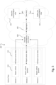
- Fig. 1 illustrates a schematic flow chart of a method 100 for Adaptive High Beam Control (AHBC) for a vehicle in accordance with some embodiments.
- the method 100 is preferably a computer-implemented method 100, performed by a processing system of the vehicle.
- the processing system may for example comprise one or more processors and one or more memories coupled to the one or more processors, wherein the one or more memories store one or more programs that perform the steps, services and functions of the method 100 disclosed herein when executed by the one or more processors.
- the method 100 comprises obtaining 101 information about an existence of streetlighting for an upcoming road segment ahead of the vehicle from a digital map layer based on a current position of the vehicle.
- the term "obtaining” is herein to be interpreted broadly and encompasses receiving, retrieving, collecting, acquiring, and so forth directly and/or indirectly between two entities configured to be in communication with each other or further with other external entities.
- the digital map layer is formed from probe sourced data from a fleet of vehicles and comprises a plurality of street light blocks.
- the digital map layer may be a layer of a standard definition map (SD-map) or a high definition map (HD-map), where the SD-map or HD-map accordingly comprises a streetlight layer having a plurality of the streetlight blocks where each streetlight block has a start and an end along a road and each streetlight block defines a road segment having one or more streetlights.
- the streetlight blocks may be construed as indications in the digital map representative of road segments that have streetlights associated thereto.
- a limited and continuous series of streetlights placed along one or both sides of a road segment forms a streetlight block.
- each streetlight block comprises a plurality of streetlights, where neighbouring streetlights, along the same road, whose distance from each other is below a distance value are comprised within the same streetlight block.
- the method 100 may further comprise obtaining 103 the position of the vehicle.
- the position of the vehicle may be construed as the vehicle's geographical position, such as a map position (may also be referred to as in-map position) of the vehicle.
- a geographical position or map position can be understood as a set (two or more) of coordinates in a global coordinate system.
- the method 100 comprises controlling 102 an illumination of a space in front of the vehicle based on the obtained information about the existence of streetlighting for the upcoming road segment so to avoid casting high beam illumination towards road areas associated with streetlights.
- an AHBC unit/function of a vehicle may be configured to use the digital map layer as an input for controlling the illumination of the space in front of the vehicle. Accordingly, the illumination may be controlled before the vehicle enters to an urban area (indicated by the upcoming streetlight block), thereby safety for both the driver and other road users may be improved.
- the method 100 further comprises obtaining 104 speed data of the vehicle, and the controlling 102 the illumination of the space in front of the vehicle is further based on the obtained speed data.
- Speed data of the vehicle may also be an indication of an upcoming urban environment, i.e., the driving speed of the vehicle may be assumed to be low when entering or traveling within an urban area. Accordingly, in response to the driving speed of the vehicle being less than a speed value (e.g., 60 km/h, 50 km/h, 40 km/h, etc.), the method 100 may comprise controlling 102 an illumination of a space in front of the vehicle based on the obtained speed data of the vehicle so to avoid casting high beam illumination, as this may be used as a proxy indicator of the vehicle being in or approaching an urban area.
- a speed value e.g. 60 km/h, 50 km/h, 40 km/h, etc.
- the method 100 comprises obtaining 105 sensor data indicative of a presence of one or more streetlight poles in a surrounding environment of the vehicle from one or more sensors configured to monitor the surrounding environment of the vehicle and the controlling 102 the illumination of the space in front of the vehicle may be further based on the presence of one or more streetlight poles as indicated by the obtained 105 sensor data.
- the surrounding environment of the ego-vehicle can be understood as a general area around the ego-vehicle in which objects (such as other vehicles, landmarks, obstacles, etc.) can be detected and identified by vehicle sensors (radar, LIDAR, cameras, etc.), i.e. within a sensor range of the ego-vehicle.
- the method 100 may comprise detecting one or more streetlight poles based on sensor data.
- the sensor data may be obtained from on-board sensors, such as cameras, LIDARs and RADARs etc.
- the obtained sensor data indicative of a presence of one or more streetlight poles may be used as a proxy indicator of an urban area, i.e., in order to assess whether the vehicle is approaching an urban area or traveling in an urban area.
- the obtained 105 sensor data may be assessed based on a time-series fluctuation, e.g., an indicated streetlight pole number of a detection frame unit may be compared with an indicated streetlight pole number of a previous detection frame unit. An increasing number of the street light poles may be an indication of an upcoming urban area.
- the number streetlight poles may be counted and evaluated as a total number or as a number per unit of distance. Above a certain number, it may be assumed that an urban environment is ahead or entered. Thus, in response to the obtained 105 sensor data indicates an upcoming urban area, such as in response to the number of streetlight poles being more than a certain number or more than a certain number per unit of distance, the method 100 may comprise controlling 102 an illumination of a space in front of the vehicle so to avoid casting high beam illumination.
- the method 100 may comprise obtaining 106 sensor data comprising ambient lighting information of a surrounding environment of the vehicle from one or more sensors configured to monitor the surrounding environment of the vehicle.
- the controlling 102 the illumination of the space in front of the vehicle may be further based on the obtained 106 ambient lighting information of the surrounding environment.
- the method 100 may comprise obtaining 106 ambient lighting information based on sensor data.
- the sensor may be a daylight sensor, a camera or any other sensor configured for sensing brightness within the field of view of the sensor. If the obtained 106 sensor data indicates day-light conditions the method 100 may comprise controlling 102 an illumination of a space in front of the vehicle so to avoid casting high beam illumination.
- the method 100 may comprise controlling 102 an illumination of the space in front of the vehicle so to cast high-beam illumination towards an area in front of the vehicle, unless other conditions are satisfied, such as that the vehicle is approaching, traveling within, or traveling along a streetlight block, the speed being below a speed value, sensor data indicating presence of streetlight poles, and/or sensor data indicating of a presence of another vehicle in front of the ego-vehicle.
- the term “if” may be construed to mean “when” or “upon” or “in response to determining” or “in response to detecting” depending on the context.
- the term “if the obtained sensor data indicates ambient lighting information” may be construed to "upon detecting and identifying night-time or day-time” or “in response to detecting night-time or day-time”.
- the phrase “if it is determined' or “when it is determined” or “in an instance of” may be construed to mean “upon determining or “in response to determining” or “upon detecting and identifying occurrence of an event” or “in response to detecting occurrence of an event” depending on the context.
- the method 100 comprises obtaining 107 information about a speed limit for the upcoming road segment ahead of the vehicle from the digital map based on the current position of the vehicle and/or from one or more sensors configured to monitor a surrounding environment of the vehicle.
- the speed limit of the upcoming road segment may be obtained from a digital map comprising speed limit information for specific road segments, based on the current position of the vehicle.
- speed limit signs along the road may be monitored continuously by sensors, such as forward-facing cameras of the vehicle, and the associated speed limit for an upcoming road segment may be derived from the sensor data.
- the obtained information of the speed limit may be an indication of a probable speed, such as driving speed of the vehicle.
- the speed limit may therefore be a proxy indicator for the driving speed.
- obtained information of the speed limit indicates the speed limit as X km/h, it may be assumed that the vehicle speed is X km/h or lower.
- obtained 107 information about a speed limit for the upcoming road segment may compose basis for detecting whether the vehicle is approaching an urban area. Accordingly, in some embodiments, the method 100 comprises controlling 102 the illumination of the space in front of the vehicle based on the obtained information about the speed limit for the upcoming road segment.
- the method 100 further comprises controlling 102 an illumination of a space in front of the vehicle further based on a combination one or more of the following: data indicative of a presence of one or more streetlight poles in a surrounding environment of the vehicle, speed data of the vehicle, or ambient lighting information of the surrounding environment of the vehicle.
- Executable instructions for performing these functions are, optionally, included in a non-transitory computer-readable storage medium or other computer program product configured for execution by one or more processors.
- FIG. 2 is a schematic illustration of a pair of streetlight blocks in accordance with some embodiments.
- Each streetlight block 21, 22 comprise one or more streetlights 211a-d, 222a-c and defines a road segment having the streetlights 211a-d, 222a-c. It should be noted that the illustrations herein are not necessarily to-scale and primarily serve the purpose to facilitate the understanding of the described embodiments.
- a streetlight block 21, 22 may be defined by a plurality of streetlights or streetlight poles 211a-d, 222a-c, where a distance 28 between neighbouring streetlights is below a set distance value 29.
- a first streetlight block 21 in Fig. 2 comprises four streetlights 211a-d where the distance 28 between neighbouring/adjacent streetlights is below the set distance value 29. The distance between neighbouring streetlights may be the same or it may differ.
- a second streetlight block 22 of Fig. 2 comprises three streetlights 222a-c, where the distance 28 between neighbouring streetlights is below the set distance value 29.
- the distance 28 between neighbouring streetlights may be the same or may differ.
- the streetlights 222a-c are comprised within the same streetlight block 22.
- the set distance value 29 may for example be in the range of 50m to 500m, such as e.g., 100m, 200m, 250m, or 300m.
- each streetlight block 21, 22 comprises a start and an end (may also be referred to as starting location and ending location) along the road 30.
- the digital map layer indicates starting and ending location of each streetlight blocks 21, 22.
- the starting and ending locations of a streetlight block may be based on the location of a first streetlight 211a, 222a and the location a last streetlight 211d, 222c within the respective streetlight block 21, 22.
- the starting location of the first streetlight block 21 may be based on the localization of the streetlight 211a that appears first along the driving direction (indicated with an arrow in Fig. 2 ).
- the ending location of the first streetlight block 21 may be the last streetlight 211d that appears the last along the driving direction.
- each street light block 21, 22 may be aligned with the location of the first streetlight 211a, 222a and last streetlight 211d, 222c in each block 21, 22 respectively.
- the start of each streetlight block 21, 22 may be set some distance (e.g., 10m, 20m, 50m, 100m, 200m, etc.) before the first streetlight 211a, 222a and the end of each streetlight block 21, 22 may be set some distance after the last streetlight 211d, 222c.
- the terms "before” and “after” in this context could be understood as “in front of” and “behind” from the perspective of the traveling direction of the vehicle.
- the streetlight blocks 21, 22 may be defined as geofenced areas within the digital map layer as indicated in Fig. 2 .
- the geofenced areas may accordingly enclose the streetlights 211a-d, 222a-c of the respective block 21, 22 and the associated road portion/segment.
- the illumination space in front of the vehicle may be controlled based on the vehicle's position relative to the geofenced area defining the streetlight blocks so to avoid casting high beam illumination towards road areas associated with streetlights.
- FIG. 3 Yet another schematic top-view illustration of a pair of streetlight blocks 23, 24 defining a respective road segment of a road 31, 32 having one or more streetlights associated thereto.in accordance with some embodiments is shown in Fig. 3 .
- Each streetlight block 23, 24, 25 defines a road segment having one or more streetlights 233a-c, 234a-c, 244a-d, 245a-d, 255a-b.
- a first streetlight block 23 comprises three streetlights 233a-c, 234a-c on each side of a common associated road segment of a road 31.
- Fig. 3 also depicts a road segment 33 without any associated streetlights and therefore no streetlight blocks.
- Fig. 3 further illustrates two alternative geofencing solutions in each respective streetlight block 23.
- the first streetlight block 23 is defined as geofenced area enclosing both the streetlights 233a-c, 234a-c and the associated road segment of the road 31.
- the second streetlight block 24 is defined as geofenced area enclosing the road segment of the road 32 without enclosing the streetlights 244a-d, 245a-d associated thereto.
- Using a geofencing solution that encloses the road segment having one or more streetlights facilitates the implementation of the AHBC as discussed herein, and provides for a simple and robust means for the AHBC to be controlled so to avoid casting high beam illumination towards road areas associated with streetlights.
- each streetlight block 21-24 may only encompass a single continuous road.
- a single continuous road is to be understood a stretch of road absent of road splits or road crossings.
- the set distance value 29 e.g., streetlight 233c and 244a in Fig. 3
- any type of road split or road crossing would result in a new streetlight block starting for the diverging road segment, assuming that there are streetlights along the road segment after the road split or road crossing.
- Fig. 4 is a schematic illustration of a vehicle 1 comprising a system 10 for Adaptive High Beam Control (AHBC) for the vehicle in accordance with some embodiments.
- a vehicle is any form of motorized transport.
- the vehicle 1 may be any road vehicle such as a car (as illustrated herein), a motorcycle, a (cargo) truck, a bus, etc.
- the system 10 comprises control circuitry 11 and a memory 12.
- the control circuitry 11 may physically comprise one single circuitry device. Alternatively, the control circuitry 11 may be distributed over several circuitry devices. As an example, the apparatus 10 may share its control circuitry 11 with other parts of the vehicle 1 (e.g. the Automated Driving System (ADS) 310). Moreover, the system 10 may form a part of the ADS 310, i.e. the system 10 may be implemented as a module or feature of the ADS.
- ADS as used herein is to be understood as an Advanced Driver Assistance System (ADAS) or an Autonomous Driving (AD) system.
- ADS as used herein may comprise one or more features or functions of any level 0-5 according to SAE J3016 levels of driving automation for on-road vehicles.
- the apparatus 10 forms a part of the AHBC unit 340.
- the control circuitry 11 may comprise one or more processors, such as a central processing unit (CPU), microcontroller, or microprocessor.
- the one or more processors may be configured to execute program code stored in the memory 12, in order to carry out various functions and operations of the vehicle 1 in addition to the methods disclosed herein.
- the processor(s) may be or include any number of hardware components for conducting data or signal processing or for executing computer code stored in the memory 12.
- the memory 12 optionally includes high-speed random-access memory, such as DRAM, SRAM, DDR RAM, or other random-access solid-state memory devices; and optionally includes non-volatile memory, such as one or more magnetic disk storage devices, optical disk storage devices, flash memory devices, or other non-volatile solid-state storage devices.
- the memory 12 may include database components, object code components, script components, or any other type of information structure for supporting the various activities of the present description.
- the memory 12 further stores map data 308.
- the map data 308 may for instance be used by the ADS 310 of the vehicle 1 in order to perform autonomous functions of the vehicle 1.
- the map data 308 may comprise standard-definition (SD) map data and/or high-definition (HD) map data.
- the map data 308 may comprise the digital map layer comprising streetlighting information as described in the foregoing. It is contemplated that the memory 12, even though illustrated as a separate element from the ADS 310, may be provided as an integral element of the ADS 310.
- the map data 308 may be stored in a remote server (e.g., a cloud server) whereupon the map data is streamed or otherwise provided to the vehicle from the remote server.
- a remote server e.g., a cloud server
- the vehicle may request specific portions of the map data based on a current position and estimated route of the vehicle, thereby avoiding using up memory storage space in the vehicle for irrelevant map data.
- any distributed or local memory device may be utilized in the realization of the present inventive concept.
- the control circuitry 11 may be distributed e.g. such that one or more processors of the control circuitry 11 is provided as integral elements of the ADS 310 or any other system of the vehicle 1.
- any distributed or local control circuitry device may be utilized in the realization of the present inventive concept.
- the ADS 310 is configured carry out the functions and operations of the autonomous or semi-autonomous functions of the vehicle 1.
- the ADS 310 can comprise a number of modules, where each module is tasked with different functions of the ADS 310.
- the vehicle 1 comprises a number of elements which can be commonly found in autonomous or semi-autonomous vehicles. It will be understood that the vehicle 1 can have any combination of the various elements shown in Fig. 4 . Moreover, the vehicle 1 may comprise further elements than those shown in Fig. 4 . While the various elements are herein shown as located inside the vehicle 1, one or more of the elements can be located externally to the vehicle 1. For example, the map data may be stored in a remote server and accessed by the various components of the vehicle 1 via the communication system 326. Further, even though the various elements are herein depicted in a certain arrangement, the various elements may also be implemented in different arrangements, as readily understood by the skilled person. It should be further noted that the various elements may be communicatively connected to each other in any suitable way. The vehicle 1 of Fig. 5 should be seen merely as an illustrative example, as the elements of the vehicle 1 can be realized in several different ways.
- the vehicle 1 further comprises a sensor system 320.
- the sensor system 320 is configured to acquire sensory data about the vehicle itself, or of its surroundings.
- the sensor system 320 may for example comprise a Global Navigation Satellite System (GNSS) module 322 (such as a GPS) configured to collect geographical position data of the vehicle 1.
- GNSS Global Navigation Satellite System
- the sensor system 320 may further comprise one or more sensors 324.
- the sensor(s) 324 may be any type of on-board sensors, such as cameras, LIDARs and RADARs, ultrasonic sensors, gyroscopes, accelerometers, odometers etc. It should be appreciated that the sensor system 320 may also provide the possibility to acquire sensory data directly or via dedicated sensor control circuitry in the vehicle 1.
- the vehicle 1 further comprises a communication system 326.
- the communication system 326 is configured to communicate with external units, such as other vehicles (i.e. via vehicle-to-vehicle (V2V) communication protocols), remote servers (e.g. cloud servers), databases or other external devices, i.e. vehicle-to-infrastructure (V2I) or vehicle-to-everything (V2X) communication protocols.
- the communication system 318 may communicate using one or more communication technologies.
- the communication system 318 may comprise one or more antennas (not shown).
- Cellular communication technologies may be used for long range communication such as to remote servers or cloud computing systems.
- the cellular communication technology used may also be used for V2V, V2l or V2X communication.
- Examples of cellular radio technologies are GSM, GPRS, EDGE, LTE, 5G, 5G NR, and so on, also including future cellular solutions.
- GSM Global System for Mobile communications
- GPRS Global System for Mobile communications
- EDGE Evolved Universal Terrestrial Radio Access
- LTE Long Term Evolution
- 5G 5G NR
- future cellular solutions such as Wireless Local Area (LAN), e.g. IEEE 802.11 based solutions, for communicating with other vehicles in the vicinity of the vehicle 1 or with local infrastructure elements.
- LAN Wireless Local Area
- ETSI is working on cellular standards for vehicle communication and for instance 5G is considered as a suitable solution due to the low latency and efficient handling of high bandwidths and communication channels.
- the communication system 326 may accordingly provide the possibility to send output to a remote location (e.g. remote operator or control center) and/or to receive input from a remote location by means of the one or more antennas. Moreover, the communication system 326 may be further configured to allow the various elements of the vehicle 1 to communicate with each other. As an example, the communication system may provide a local network setup, such as CAN bus, 12C, Ethernet, optical fibers, and so on. Local communication within the vehicle may also be of a wireless type with protocols such as WiFi, LoRa, Zigbee, Bluetooth, or similar mid/short range technologies.
- the vehicle 1 further comprises a maneuvering system 320.
- the maneuvering system 328 is configured to control the maneuvering of the vehicle 1.
- the maneuvering system 328 comprises a steering module 330 configured to control the heading of the vehicle 1.
- the maneuvering system 328 further comprises a throttle module 332 configured to control actuation of the throttle of the vehicle 1.
- the maneuvering system 328 further comprises a braking module 334 configured to control actuation of the brakes of the vehicle 1.
- the various modules of the maneuvering system 328 may also receive manual input from a driver of the vehicle 1 (i.e. from a steering wheel, a gas pedal and a brake pedal respectively).
- the maneuvering system 328 may be communicatively connected to the ADS 310 of the vehicle, to receive instructions on how the various modules of the maneuvering system 328 should act.
- the ADS 310 can control the maneuvering of the vehicle 1, for example via the decision and control module 318.
- the vehicle 1 further comprises a lighting system (not shown) for controlling the external lights of the vehicle 1.
- the lighting system may for example be operatively connected to the AHBC unit 340 so to receive input signals from the AHBC unit 340.
- the AHBC unit 340 may be configured to output signals to the lighting system in order to control the headlights of the vehicle 1 and in particular the high beams of the vehicle.
- the lighting system may further control activation/deactivation of various external lights of the vehicle 1 such as turn indicators, brake lights, reverse lights, and so forth based on an input from various control systems of the vehicle 1.
- the ADS 310 may comprise a localization module 312 or localization block/system.
- the localization module 312 is configured to determine and/or monitor a geographical position and heading of the vehicle 1, and may utilize data from the sensor system 320, such as data from the GNSS module 322. Alternatively, or in combination, the localization module 312 may utilize data from the one or more sensors 324.
- the localization system may alternatively be realized as a Real Time Kinematics (RTK) GPS in order to improve accuracy.
- RTK Real Time Kinematics
- the ADS 310 may further comprise a perception module 314 or perception block/system 314.
- the perception module 314 may refer to any commonly known module and/or functionality, e.g. comprised in one or more electronic control modules and/or nodes of the vehicle 1, adapted and/or configured to interpret sensory data - relevant for driving of the vehicle 1 - to identify e.g. obstacles, vehicle lanes, relevant signage, appropriate navigation paths etc.
- the perception module 314 may thus be adapted to rely on and obtain inputs from multiple data sources, such as automotive imaging, image processing, computer vision, and/or in-car networking, etc., in combination with sensory data e.g. from the sensor system 320.
- the localization module 312 and/or the perception module 314 may be communicatively connected to the sensor system 320 in order to receive sensory data from the sensor system 320.
- the localization module 312 and/or the perception module 314 may further transmit control instructions to the sensor system 320.
- the system 10 for Adaptive High Beam Control comprises one or more memory storage areas 12 comprising program code, the one or more memory storage areas 12 and the program code being configured to, with the one or more processors 11, cause the system 10 to at least obtain information about an existence of streetlighting for an upcoming road segment ahead of the vehicle from a digital map layer based on a current position of the vehicle.
- the digital map layer is formed from probe sourced data from a fleet of vehicles.
- the digital map layer comprises a plurality of streetlight blocks, where each streetlight block comprises a start and an end along a road, and each streetlight block defines a road segment having one or more streetlights.
- the program code is configured to cause the system 10 to control an illumination of a space in front of the vehicle based on the obtained information about the existence of streetlighting for the upcoming road segment so to avoid casting high beam illumination towards road areas associated with streetlights.
- the one or more memory storage areas 12 and the program code may be configured to, with the one or more processors 11, cause the system 10 to at least obtain speed data of the vehicle 1. Accordingly, the control of the illumination of the space in front of the vehicle may be further based on the obtained speed data.
- the one or more memory storage areas 12 and the program code may be configured to, with the one or more processors 11, cause the system 10 to at least obtain sensor data indicative of a presence of one or more streetlight poles in a surrounding environment of the vehicle 1 from one or more sensors 324 configured to monitor the surrounding environment of the vehicle 1. Accordingly, the control of the illumination of the space in front of the vehicle 1 may be further based on the presence of one or more streetlight poles.
- the one or more memory storage areas 12 and the program code is configured to, with the one or more processors 11, cause the system 10 to at least obtain sensor data comprising ambient lighting information of a surrounding environment of the vehicle from one or more sensors 324 configured to monitor the surrounding environment of the vehicle. Accordingly, the control of the illumination of the space in front of the vehicle 1 may be further based on the obtained ambient lighting information of the surrounding environment.
- the one or more memory storage areas 12 and the program code is configured to, with the one or more processors 11, cause the system 10 to at least obtain information about a speed limit for the upcoming road segment ahead of the vehicle 1 from the digital map 308 based on the current position of the vehicle and/or from one or more sensors 324 configured to monitor a surrounding environment of the vehicle 1. Accordingly, the control of the illumination of the space in front of the vehicle may be further based on the obtained information about the speed limit for the upcoming road segment.
- FIG. 5 is a schematic flow chart of a method 400 for building a streetlight map layer within a digital map in accordance with some embodiments.
- the method 400 comprises storing 420 streetlighting information sourced from a fleet of vehicles.
- each vehicle may be configured to transmit 510 its map position (i.e., geographical position, e.g., GNSS position) and to transmit 515 sensor data to a central server (e.g., a fleet management system) via a communications network (e.g., WLAN or cellular network).
- the transmitted 515 sensor data comprises information about a presence of streetlighting along a road segment upon which the vehicle is traveling or has travelled.
- the sensor data may comprise a position of one or more streetlight poles relative to the vehicle.
- the stored 420 streetlighting information may accordingly comprise an indication of a presence of streetlighting along one or more road segments and the location of these road segments.
- the stored 420 streetlighting information is then aggregated 425 over time based on the reported data from each vehicle in the vehicle fleet.
- the method 400 may further comprise checking if the aggregated 425 information indicates a presence of a new street light block or if it is already encompassed by an existing street light block.
- the digital map is updated 430.
- the streetlight map layer is updated 430 in response to the aggregated 425 information indicating a presence of a new street light block.
- no update is performed.
- the method 400 comprises transmitting the updated 430 digital map to the fleet of vehicles.
- a non-transitory computer-readable storage medium storing one or more programs configured to be executed by one or more processors of a vehicle control system, the one or more programs comprising instructions for performing the method according to any one of the above-discussed embodiments.
- a cloud computing system may be configured to perform any of the methods presented herein.
- the cloud computing system may comprise distributed cloud computing resources that jointly perform the methods presented herein under control of one or more computer program products.
Landscapes
- Engineering & Computer Science (AREA)
- Mechanical Engineering (AREA)
- Lighting Device Outwards From Vehicle And Optical Signal (AREA)
Priority Applications (3)
| Application Number | Priority Date | Filing Date | Title |
|---|---|---|---|
| EP23200208.9A EP4530128A1 (de) | 2023-09-27 | 2023-09-27 | Verbesserte adaptive fernlichtsteuerung unter berücksichtigung von strassenabschnitten mit strassenbeleuchtungen |
| US18/897,429 US20250100441A1 (en) | 2023-09-27 | 2024-09-26 | Streetlight blocks enhanced adaptive high beam control |
| CN202411357592.2A CN119705266A (zh) | 2023-09-27 | 2024-09-27 | 路灯区块增强的自适应远光控制 |
Applications Claiming Priority (1)
| Application Number | Priority Date | Filing Date | Title |
|---|---|---|---|
| EP23200208.9A EP4530128A1 (de) | 2023-09-27 | 2023-09-27 | Verbesserte adaptive fernlichtsteuerung unter berücksichtigung von strassenabschnitten mit strassenbeleuchtungen |
Publications (1)
| Publication Number | Publication Date |
|---|---|
| EP4530128A1 true EP4530128A1 (de) | 2025-04-02 |
Family
ID=88207134
Family Applications (1)
| Application Number | Title | Priority Date | Filing Date |
|---|---|---|---|
| EP23200208.9A Pending EP4530128A1 (de) | 2023-09-27 | 2023-09-27 | Verbesserte adaptive fernlichtsteuerung unter berücksichtigung von strassenabschnitten mit strassenbeleuchtungen |
Country Status (3)
| Country | Link |
|---|---|
| US (1) | US20250100441A1 (de) |
| EP (1) | EP4530128A1 (de) |
| CN (1) | CN119705266A (de) |
Citations (9)
| Publication number | Priority date | Publication date | Assignee | Title |
|---|---|---|---|---|
| JP4163413B2 (ja) * | 2000-12-27 | 2008-10-08 | アイシン・エィ・ダブリュ株式会社 | 車両用灯具の配光制御システム |
| DE102016012701A1 (de) * | 2016-10-25 | 2017-06-08 | Daimler Ag | Verfahren zur Steuerung einer Lichtverteilung |
| CN107613618A (zh) * | 2017-09-16 | 2018-01-19 | 刘洪文 | 汽车远近光灯控制系统及方法 |
| EP1599905B1 (de) * | 2003-02-21 | 2018-07-25 | Gentex Corporation | Automatische fahrzeugaussenlichtsteuersysteme |
| US20200055442A1 (en) * | 2018-05-04 | 2020-02-20 | International Business Machines Corporation | Adaptive headlights for the trajectory of a vehicle |
| CN111241972A (zh) * | 2020-01-06 | 2020-06-05 | 广州小鹏汽车科技有限公司 | 一种车辆控制方法、装置、车辆及计算机可读存储介质 |
| EP3211372B1 (de) * | 2016-02-25 | 2020-09-30 | HERE Global B.V. | Kartierung von strassenbeleuchtung |
| CN115837876A (zh) * | 2023-02-17 | 2023-03-24 | 徐州昊德照明有限公司 | 一种车辆灯具控制系统 |
| CN116801461A (zh) * | 2023-07-18 | 2023-09-22 | 合众新能源汽车股份有限公司 | 车辆远光灯控制系统、路灯控制系统、方法及相关设备 |
Family Cites Families (12)
| Publication number | Priority date | Publication date | Assignee | Title |
|---|---|---|---|---|
| US5796094A (en) * | 1993-02-26 | 1998-08-18 | Donnelly Corporation | Vehicle headlight control using imaging sensor |
| US7655894B2 (en) * | 1996-03-25 | 2010-02-02 | Donnelly Corporation | Vehicular image sensing system |
| US6587573B1 (en) * | 2000-03-20 | 2003-07-01 | Gentex Corporation | System for controlling exterior vehicle lights |
| US6611610B1 (en) * | 1997-04-02 | 2003-08-26 | Gentex Corporation | Vehicle lamp control |
| AU2003298558A1 (en) * | 2002-08-21 | 2004-05-04 | Gentex Corporation | Image acquisition and processing methods for automatic vehicular exterior lighting control |
| US7804980B2 (en) * | 2005-08-24 | 2010-09-28 | Denso Corporation | Environment recognition device |
| EP1837803A3 (de) * | 2006-03-24 | 2008-05-14 | MobilEye Technologies, Ltd. | Vorderlicht-, Schlusslicht- und Straßenbeleuchtungsdetektion |
| WO2011106578A2 (en) * | 2010-02-26 | 2011-09-01 | Gentex Corporation | Automatic vehicle equipment monitoring, warning, and control system |
| EP3236212B1 (de) * | 2016-04-22 | 2023-01-25 | Volvo Car Corporation | Verfahren zur erzeugung von navigationsdaten und navigationsvorrichtung zur durchführung des verfahrens |
| US11676403B2 (en) * | 2021-01-21 | 2023-06-13 | Hitachi Astemo, Ltd. | Combining visible light camera and thermal camera information |
| US20230169860A1 (en) * | 2021-11-29 | 2023-06-01 | Avinash Vijai Singh | System and method for tracking vehicles |
| JP7567772B2 (ja) * | 2021-12-27 | 2024-10-16 | トヨタ自動車株式会社 | 車両灯火制御装置 |
-
2023
- 2023-09-27 EP EP23200208.9A patent/EP4530128A1/de active Pending
-
2024
- 2024-09-26 US US18/897,429 patent/US20250100441A1/en active Pending
- 2024-09-27 CN CN202411357592.2A patent/CN119705266A/zh active Pending
Patent Citations (9)
| Publication number | Priority date | Publication date | Assignee | Title |
|---|---|---|---|---|
| JP4163413B2 (ja) * | 2000-12-27 | 2008-10-08 | アイシン・エィ・ダブリュ株式会社 | 車両用灯具の配光制御システム |
| EP1599905B1 (de) * | 2003-02-21 | 2018-07-25 | Gentex Corporation | Automatische fahrzeugaussenlichtsteuersysteme |
| EP3211372B1 (de) * | 2016-02-25 | 2020-09-30 | HERE Global B.V. | Kartierung von strassenbeleuchtung |
| DE102016012701A1 (de) * | 2016-10-25 | 2017-06-08 | Daimler Ag | Verfahren zur Steuerung einer Lichtverteilung |
| CN107613618A (zh) * | 2017-09-16 | 2018-01-19 | 刘洪文 | 汽车远近光灯控制系统及方法 |
| US20200055442A1 (en) * | 2018-05-04 | 2020-02-20 | International Business Machines Corporation | Adaptive headlights for the trajectory of a vehicle |
| CN111241972A (zh) * | 2020-01-06 | 2020-06-05 | 广州小鹏汽车科技有限公司 | 一种车辆控制方法、装置、车辆及计算机可读存储介质 |
| CN115837876A (zh) * | 2023-02-17 | 2023-03-24 | 徐州昊德照明有限公司 | 一种车辆灯具控制系统 |
| CN116801461A (zh) * | 2023-07-18 | 2023-09-22 | 合众新能源汽车股份有限公司 | 车辆远光灯控制系统、路灯控制系统、方法及相关设备 |
Also Published As
| Publication number | Publication date |
|---|---|
| CN119705266A (zh) | 2025-03-28 |
| US20250100441A1 (en) | 2025-03-27 |
Similar Documents
| Publication | Publication Date | Title |
|---|---|---|
| US12005904B2 (en) | Autonomous driving system | |
| US10198944B2 (en) | Automatic driving device | |
| US10787172B2 (en) | Driving assistance device and driving assistance method | |
| JP6219312B2 (ja) | 道路の車線の車線交通路内の車両の位置を決定する方法、並びに2つの車両間の整列及び衝突リスクを検知する方法 | |
| EP3358545B1 (de) | Fahrwegsteuerungsverfahren und fahrwegsteuerungsvorrichtung | |
| JP5802659B2 (ja) | 車両の構成要素を制御する方法 | |
| JP7620440B2 (ja) | 自動運転支援システム | |
| US11214258B2 (en) | Driving assistance system and driving assistance device | |
| CN111508276B (zh) | 基于高精地图的v2x逆向超车预警方法、系统和介质 | |
| KR20210030975A (ko) | 주행 지원 방법 및 주행 지원 장치 | |
| WO2017010209A1 (ja) | 周辺環境認識装置、及びコンピュータプログラム製品 | |
| CN105608927A (zh) | 警告装置 | |
| JP7043765B2 (ja) | 車両走行制御方法及び装置 | |
| US12325422B2 (en) | Vehicle drive assist apparatus | |
| US20180329421A1 (en) | Road link information updating device and vehicle control system | |
| US12612066B2 (en) | Drive assist apparatus for tracking moving objects temporarily obscured by nearby stationary objects | |
| JP2023054084A (ja) | 車両用ステレオカメラ装置 | |
| JP2021068315A (ja) | 車線状態の推定方法及び推定システム | |
| JP2020160878A (ja) | 運転支援方法及び運転支援装置 | |
| US12522245B2 (en) | Computer-implemented method for managing an operational design domain's expansion for an automated driving system | |
| JP2023012649A (ja) | 車両制御装置 | |
| US20240232715A9 (en) | Lane-assignment for traffic objects on a road | |
| US20250100441A1 (en) | Streetlight blocks enhanced adaptive high beam control | |
| EP4361967A1 (de) | Situationsspezifische wahrnehmungsfähigkeit für autonome und halbautonome fahrzeuge | |
| JP7202120B2 (ja) | 運転支援装置 |
Legal Events
| Date | Code | Title | Description |
|---|---|---|---|
| PUAI | Public reference made under article 153(3) epc to a published international application that has entered the european phase |
Free format text: ORIGINAL CODE: 0009012 |
|
| STAA | Information on the status of an ep patent application or granted ep patent |
Free format text: STATUS: THE APPLICATION HAS BEEN PUBLISHED |
|
| AK | Designated contracting states |
Kind code of ref document: A1 Designated state(s): AL AT BE BG CH CY CZ DE DK EE ES FI FR GB GR HR HU IE IS IT LI LT LU LV MC ME MK MT NL NO PL PT RO RS SE SI SK SM TR |
|
| STAA | Information on the status of an ep patent application or granted ep patent |
Free format text: STATUS: REQUEST FOR EXAMINATION WAS MADE |
|
| 17P | Request for examination filed |
Effective date: 20250923 |
|
| STAA | Information on the status of an ep patent application or granted ep patent |
Free format text: STATUS: EXAMINATION IS IN PROGRESS |
|
| 17Q | First examination report despatched |
Effective date: 20251212 |