EP4530144A1 - Procédé et système de détection de collision de véhicule, et véhicule - Google Patents
Procédé et système de détection de collision de véhicule, et véhicule Download PDFInfo
- Publication number
- EP4530144A1 EP4530144A1 EP23938311.0A EP23938311A EP4530144A1 EP 4530144 A1 EP4530144 A1 EP 4530144A1 EP 23938311 A EP23938311 A EP 23938311A EP 4530144 A1 EP4530144 A1 EP 4530144A1
- Authority
- EP
- European Patent Office
- Prior art keywords
- obstacle
- vehicle
- collision detection
- preset
- distance
- Prior art date
- Legal status (The legal status is an assumption and is not a legal conclusion. Google has not performed a legal analysis and makes no representation as to the accuracy of the status listed.)
- Pending
Links
Images

Classifications
-
- B—PERFORMING OPERATIONS; TRANSPORTING
- B60—VEHICLES IN GENERAL
- B60W—CONJOINT CONTROL OF VEHICLE SUB-UNITS OF DIFFERENT TYPE OR DIFFERENT FUNCTION; CONTROL SYSTEMS SPECIALLY ADAPTED FOR HYBRID VEHICLES; ROAD VEHICLE DRIVE CONTROL SYSTEMS FOR PURPOSES NOT RELATED TO THE CONTROL OF A PARTICULAR SUB-UNIT
- B60W60/00—Drive control systems specially adapted for autonomous road vehicles
- B60W60/001—Planning or execution of driving tasks
- B60W60/0015—Planning or execution of driving tasks specially adapted for safety
- B60W60/0016—Planning or execution of driving tasks specially adapted for safety of the vehicle or its occupants
-
- B—PERFORMING OPERATIONS; TRANSPORTING
- B60—VEHICLES IN GENERAL
- B60W—CONJOINT CONTROL OF VEHICLE SUB-UNITS OF DIFFERENT TYPE OR DIFFERENT FUNCTION; CONTROL SYSTEMS SPECIALLY ADAPTED FOR HYBRID VEHICLES; ROAD VEHICLE DRIVE CONTROL SYSTEMS FOR PURPOSES NOT RELATED TO THE CONTROL OF A PARTICULAR SUB-UNIT
- B60W30/00—Purposes of road vehicle drive control systems not related to the control of a particular sub-unit, e.g. of systems using conjoint control of vehicle sub-units
- B60W30/08—Active safety systems predicting or avoiding probable or impending collision or attempting to minimise its consequences
- B60W30/095—Predicting travel path or likelihood of collision
- B60W30/0956—Predicting travel path or likelihood of collision the prediction being responsive to traffic or environmental parameters
-
- B—PERFORMING OPERATIONS; TRANSPORTING
- B60—VEHICLES IN GENERAL
- B60W—CONJOINT CONTROL OF VEHICLE SUB-UNITS OF DIFFERENT TYPE OR DIFFERENT FUNCTION; CONTROL SYSTEMS SPECIALLY ADAPTED FOR HYBRID VEHICLES; ROAD VEHICLE DRIVE CONTROL SYSTEMS FOR PURPOSES NOT RELATED TO THE CONTROL OF A PARTICULAR SUB-UNIT
- B60W40/00—Estimation or calculation of non-directly measurable driving parameters for road vehicle drive control systems not related to the control of a particular sub unit, e.g. by using mathematical models
- B60W40/02—Estimation or calculation of non-directly measurable driving parameters for road vehicle drive control systems not related to the control of a particular sub unit, e.g. by using mathematical models related to ambient conditions
- B60W40/04—Traffic conditions
-
- G—PHYSICS
- G01—MEASURING; TESTING
- G01S—RADIO DIRECTION-FINDING; RADIO NAVIGATION; DETERMINING DISTANCE OR VELOCITY BY USE OF RADIO WAVES; LOCATING OR PRESENCE-DETECTING BY USE OF THE REFLECTION OR RERADIATION OF RADIO WAVES; ANALOGOUS ARRANGEMENTS USING OTHER WAVES
- G01S17/00—Systems using the reflection or reradiation of electromagnetic waves other than radio waves, e.g. lidar systems
- G01S17/86—Combinations of lidar systems with systems other than lidar, radar or sonar, e.g. with direction finders
-
- G—PHYSICS
- G01—MEASURING; TESTING
- G01S—RADIO DIRECTION-FINDING; RADIO NAVIGATION; DETERMINING DISTANCE OR VELOCITY BY USE OF RADIO WAVES; LOCATING OR PRESENCE-DETECTING BY USE OF THE REFLECTION OR RERADIATION OF RADIO WAVES; ANALOGOUS ARRANGEMENTS USING OTHER WAVES
- G01S17/00—Systems using the reflection or reradiation of electromagnetic waves other than radio waves, e.g. lidar systems
- G01S17/88—Lidar systems specially adapted for specific applications
- G01S17/89—Lidar systems specially adapted for specific applications for mapping or imaging
-
- G—PHYSICS
- G01—MEASURING; TESTING
- G01S—RADIO DIRECTION-FINDING; RADIO NAVIGATION; DETERMINING DISTANCE OR VELOCITY BY USE OF RADIO WAVES; LOCATING OR PRESENCE-DETECTING BY USE OF THE REFLECTION OR RERADIATION OF RADIO WAVES; ANALOGOUS ARRANGEMENTS USING OTHER WAVES
- G01S17/00—Systems using the reflection or reradiation of electromagnetic waves other than radio waves, e.g. lidar systems
- G01S17/88—Lidar systems specially adapted for specific applications
- G01S17/93—Lidar systems specially adapted for specific applications for anti-collision purposes
- G01S17/931—Lidar systems specially adapted for specific applications for anti-collision purposes of land vehicles
-
- G—PHYSICS
- G08—SIGNALLING
- G08G—TRAFFIC CONTROL SYSTEMS
- G08G1/00—Traffic control systems for road vehicles
- G08G1/16—Anti-collision systems
- G08G1/165—Anti-collision systems for passive traffic, e.g. including static obstacles, trees
-
- G—PHYSICS
- G08—SIGNALLING
- G08G—TRAFFIC CONTROL SYSTEMS
- G08G1/00—Traffic control systems for road vehicles
- G08G1/16—Anti-collision systems
- G08G1/166—Anti-collision systems for active traffic, e.g. moving vehicles, pedestrians, bikes
-
- G—PHYSICS
- G08—SIGNALLING
- G08G—TRAFFIC CONTROL SYSTEMS
- G08G1/00—Traffic control systems for road vehicles
- G08G1/16—Anti-collision systems
- G08G1/168—Driving aids for parking, e.g. acoustic or visual feedback on parking space
-
- B—PERFORMING OPERATIONS; TRANSPORTING
- B60—VEHICLES IN GENERAL
- B60W—CONJOINT CONTROL OF VEHICLE SUB-UNITS OF DIFFERENT TYPE OR DIFFERENT FUNCTION; CONTROL SYSTEMS SPECIALLY ADAPTED FOR HYBRID VEHICLES; ROAD VEHICLE DRIVE CONTROL SYSTEMS FOR PURPOSES NOT RELATED TO THE CONTROL OF A PARTICULAR SUB-UNIT
- B60W2520/00—Input parameters relating to overall vehicle dynamics
- B60W2520/06—Direction of travel
-
- B—PERFORMING OPERATIONS; TRANSPORTING
- B60—VEHICLES IN GENERAL
- B60W—CONJOINT CONTROL OF VEHICLE SUB-UNITS OF DIFFERENT TYPE OR DIFFERENT FUNCTION; CONTROL SYSTEMS SPECIALLY ADAPTED FOR HYBRID VEHICLES; ROAD VEHICLE DRIVE CONTROL SYSTEMS FOR PURPOSES NOT RELATED TO THE CONTROL OF A PARTICULAR SUB-UNIT
- B60W2554/00—Input parameters relating to objects
-
- G—PHYSICS
- G08—SIGNALLING
- G08G—TRAFFIC CONTROL SYSTEMS
- G08G1/00—Traffic control systems for road vehicles
- G08G1/16—Anti-collision systems
-
- Y—GENERAL TAGGING OF NEW TECHNOLOGICAL DEVELOPMENTS; GENERAL TAGGING OF CROSS-SECTIONAL TECHNOLOGIES SPANNING OVER SEVERAL SECTIONS OF THE IPC; TECHNICAL SUBJECTS COVERED BY FORMER USPC CROSS-REFERENCE ART COLLECTIONS [XRACs] AND DIGESTS
- Y02—TECHNOLOGIES OR APPLICATIONS FOR MITIGATION OR ADAPTATION AGAINST CLIMATE CHANGE
- Y02T—CLIMATE CHANGE MITIGATION TECHNOLOGIES RELATED TO TRANSPORTATION
- Y02T10/00—Road transport of goods or passengers
- Y02T10/10—Internal combustion engine [ICE] based vehicles
- Y02T10/40—Engine management systems
Definitions
- the present application relates to the technical field of intelligent driving, in particular to a vehicle collision detection method and system, and a vehicle.
- the distance between a current vehicle and an obstacle can be acquired based on sensor data, and then collision detection analysis and warning are carried out.
- data transmitted by sensors has inaccuracies and delays, so that collision detection fails to be carried out in time.
- sensors cannot conduct corresponding collision detection for different vehicles according to the height of an obstacle, resulting in the collision between the current vehicle and the obstacle in the driving process, which may cause casualties in serious cases.
- the present application provides a method and system capable of carrying out vehicle collision detection based on height of obstacles.
- the present application provides a vehicle collision detection method.
- the method includes the following steps:
- the obstacle maps are divided according to the height of an obstacle, then the corresponding collision detection models are built, and the distance relationship between the current vehicle and the obstacle is determined through the collision detection models to obtain the collision risk.
- the collision risk may be analyzed accurately in real time for different types of obstacle heights, the accuracy and efficiency of collision detection are improved, and the driving safety of the vehicle and the personal safety of occupants are further guaranteed.
- step S100 dividing the collection of obstacle information into a first obstacle map and a second obstacle map based on a preset obstacle height in step S100 includes:
- step S200 includes: Modeling the current vehicle to obtain a first vehicle model including a front overhang and a rear overhang of the vehicle, and a second vehicle model with the front overhang and the rear overhang of the vehicle removed.
- the vehicle models are obtained and fused into the corresponding obstacle maps to obtain the corresponding collision detection models for use in subsequent analysis of collision detection.
- the maximum lengths of the front and rear wheels of the current vehicle are calibrated, so that models corresponding to various vehicles and the collision detection models correspond and are unique, making the collision detection more personalized and intelligent.
- the method includes: Building a first rectangular coordinate system with a geometric center of the current vehicle as a first origin, a width direction of the current as an x-axis, and a length direction of the vehicle as a y-axis; and building a second rectangular coordinate system with a midpoint of a rear axle of the current vehicle as a second origin, the width direction of the vehicle as an X-axis, and the length direction of the vehicle as a Y-axis.
- step S300 includes:
- step S303 If the distance between at least one of the obstacles and the first origin is smaller than a first preset distance, performing step S303, otherwise performing step S305.
- step S303 Acquiring transformed obstacle coordinates of obstacles in a first preset circular region under the second rectangular coordinate system, and proceeding to step S304.
- the transformed obstacle coordinates under the second rectangular coordinate system are used here to reduce the influence of the vehicle heading angle on the obstacle coordinates, so that obtained results of the distance between the obstacle and the current vehicle are more accurate, and the accuracy of collision detection is further improved.
- S304 Calculating a distance between each obstacle in the first preset circular region and the second origin based on the transformed obstacle coordinates and coordinates of the second origin.
- step S305 If the distance between at least one of the obstacles in the first preset circular region and the second origin is smaller than a second preset distance, determining that the current vehicle is in collision, otherwise performing step S305.
- the second preset distance is typically preferably half the width of the vehicle, or the length of the rear overhang of the vehicle, or the distance between the rear axle and the front overhang of the vehicle; herein, obstacles that may collide with the vehicle are further limited, so as to determine whether the current vehicle has a risk of collision.
- the first preset circle region takes the first origin as a center of the circle and the first preset distance as a radius.
- step S300 further includes:
- step S313 If the distance between at least one of the obstacles and the first origin is smaller than a third preset distance, performing step S313, otherwise performing step S315.
- step S313 acquiring transformed obstacle coordinates of obstacles in a second preset circular region under the second rectangular coordinate system, and proceeding to step S314.
- S314 calculating a distance between each obstacle in the second preset circular region and the second origin based on the transformed obstacle coordinates and coordinates of the second origin.
- the second preset circle region takes the first origin as a center of the circle and the third preset distance as a radius.
- step S303 or S313 specifically includes: Acquiring a vehicle heading angle, corresponding initial obstacle coordinates of the obstacles in the first preset circular region or the second preset circular region under the first rectangular coordinate system, and coordinates of the midpoint of the rear axle of the vehicle under the first rectangular coordinate system.
- the transformed obstacle coordinates remove the influence of the vehicle heading angle thereon, which further helps to improve the accuracy of subsequent collision detection.
- step S304 or S314 further includes: issuing a collision warning message.
- the present application further provides a vehicle collision detection system.
- the system includes:
- a first acquisition module configured to acquire a collection of obstacle information within a preset range of a current vehicle.
- a dividing module configured to divide the collection of obstacle information into a first obstacle map and a second obstacle map based on a preset obstacle height.
- a second acquisition module configured to model the current vehicle configured based on the first obstacle map and the second obstacle map, and fuse vehicle models with the corresponding obstacle maps to obtain a first collision detection model and a second collision detection model, respectively.
- a determining module configured to obtain a distance relationship between a preset position of the current vehicle and obstacles corresponding to the collection of obstacle information through the first collision detection model and/or the second collision detection model, and determine whether the current vehicle is in collision based on the distance relationship.
- the system further includes: A building module: configured to build a first rectangular coordinate system and a second rectangular coordinate system, wherein the first rectangular coordinate system takes a geometric center of the current vehicle as a first origin, a width direction of the current as an x-axis, and a length direction of the vehicle as a y-axis; and the second rectangular coordinate system takes a midpoint of a rear axle of the current vehicle as a second origin, the width direction of the vehicle as an X-axis, and the length direction of the vehicle as a Y-axis.
- a building module configured to build a first rectangular coordinate system and a second rectangular coordinate system, wherein the first rectangular coordinate system takes a geometric center of the current vehicle as a first origin, a width direction of the current as an x-axis, and a length direction of the vehicle as a y-axis; and the second rectangular coordinate system takes a midpoint of a rear axle of the current vehicle as a second origin, the width direction of the vehicle as an X-axis, and the
- a warning module configured to issue a collision warning message when it is determined that the current vehicle is in collision.
- the dividing module includes: A calibration unit: configured to calibrate maximum lengths of front wheels and rear wheels of the current vehicle.
- a setting unit configured to set the preset obstacle height according to calibration results of the calibration unit.
- a dividing unit configured to determine whether heights of the obstacles corresponding to the collection of obstacle information are greater than the preset obstacle height; if yes, classify the obstacles into the first obstacle map; otherwise, classify the obstacles into the second obstacle map.
- the second acquisition module includes: A modeling unit: configured to obtain a first vehicle model and a second vehicle model.
- a fusion unit configured to fuse the first vehicle model and the second vehicle model with the first obstacle map and the second obstacle map, respectively, to obtain the first collision detection model and the second collision detection model.
- the determining module includes: An acquisition unit: configured to acquire, in the first collision detection model or the second collision detection model, initial obstacle coordinates of the obstacles under the first rectangular coordinate system.
- a first calculation unit configured to calculate a distance between each obstacle and the first origin based on the initial obstacle coordinates and coordinates of the first origin to obtain transformed obstacle coordinates of obstacles in a second preset circular region under the second rectangular coordinate system when the distance is smaller than a first preset distance or a third preset distance.
- a second calculation unit configured to calculate a distance between each obstacle in the second preset circular region to the second origin based on the transformed obstacle coordinates and coordinates of the second origin, so as to determine that the current vehicle is in collision when the distance is smaller than a second preset distance.
- the collision risk may be analyzed accurately for different types of obstacle heights, the accuracy of collision detection is improved, and the driving safety of the vehicle and the personal safety of occupants are further guaranteed.
- the present application further provides a vehicle.
- the vehicle is configured with a vehicle collision detection system, and the system detects whether a current vehicle is in collision using the vehicle collision detection method described above.
- the collection of obstacle information is divided into the first obstacle map and the second obstacle map, then the first collision detection model and the second collision detection model are correspondingly built, and the distance relationship between the current vehicle and the obstacle is determined through the first collision detection model or the second collision detection model, so as to obtain the collision risk between the current vehicle and the obstacle.
- the collision risk can be analyzed accurately for different types of obstacle heights, the accuracy of collision detection is improved, and the driving safety of the vehicle and the personal safety of occupants are further guaranteed.
- the present application provides a vehicle collision detection method and system and a vehicle, in order to solve the technical problems that in the prior art, collision detection is inaccurate and inefficient due to the use of sensors for the detection of the distance between a vehicle and an obstacle, and corresponding collision detection cannot be carried out for different vehicles according to the height of the obstacle.
- the present application provides a vehicle collision detection method and system and a vehicle.
- the overall solution is as follows:
- the present application provides a vehicle collision detection method.
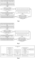
- the method includes the following steps: S 100: Acquiring a collection of obstacle information within a preset range of a current vehicle, and divide the collection of obstacle information into a first obstacle map and a second obstacle map based on a preset obstacle height.
- step S100 dividing the collection of obstacle information into a first obstacle map and a second obstacle map based on a preset obstacle height in step S100 includes:
- the preset obstacle height is calibrated according to an actual vehicle, and the specific value of the preset obstacle height is not limited herein.
- the first obstacle map is a body non-encroachable map and the second obstacle map is a body encroachable map, where body encroachable means that front and rear overhangs of the vehicle are encroachable due to a limiter or a low curb or the like.
- step S200 may be performed.
- S200 Modeling the current vehicle based on the first obstacle map and the second obstacle map, and fuse vehicle models with the corresponding obstacle maps to obtain a first collision detection model and a second collision detection model, respectively.
- step S200 includes: Modeling the current vehicle to obtain a first vehicle model including a front overhang and a rear overhang of the vehicle, and a second vehicle model with the front overhang and the rear overhang of the vehicle removed.
- the vehicle models are not 3d models, but twodimensional planar models of the surrounding contour of a vehicle.
- the first vehicle model is the surrounding contour of the entire vehicle including the front and rear overhangs of the vehicle, presenting a rounded rectangle, and the front and rear wheels of the vehicle are correspondingly identified by four rectangles, respectively.
- the second vehicle model is a rectangular contour map with the front and rear overhangs of the vehicle removed, and the corners of the contour map are where the wheels are located.
- the first vehicle model and the second vehicle model are fused with the first obstacle map and the second obstacle map, respectively, to obtain the first collision detection model and the second collision detection model.
- the first collision detection model or the second collision detection model may embody a position of an obstacle of the collection of obstacle information relative to a corresponding vehicle model, where an obstacle is presented in the form of a data point.
- step S300 After completing the acquisition of the first collision detection model and the second collision detection model, step S300 may be performed.
- S300 Obtaining a distance relationship between a preset position of the current vehicle and obstacles corresponding to the collection of obstacle information through the first collision detection model and/or the second collision detection model, and determine whether the current vehicle is in collision based on the distance relationship.
- the method includes: Building a first rectangular coordinate system with a geometric center of the current vehicle as a first origin, a width direction of the current as an x-axis, and a length direction of the vehicle as a y-axis; and building a second rectangular coordinate system with a midpoint of a rear axle of the current vehicle as a second origin, the width direction of the vehicle as an X-axis, and the length direction of the vehicle as a Y-axis.
- step S300 includes:
- step S303 If the distance between at least one of the obstacles and the first origin is smaller than a first preset distance, step S303 is performed; otherwise step S305 is performed.
- the first preset distance is a distance between the geometric center of the current vehicle and any corner of the vehicle, because the geometric center of the vehicle is selected here, the distance between the geometric center and any corner of the vehicle is the same, and the distance may be arbitrarily selected in the practical application. For example, the distance between the geometric center of the current vehicle and the front right corner of the vehicle is measured and defined as the first preset distance.
- the positional relationship between the obstacle and the current vehicle is determined based on the distance between the geometric center of the vehicle and any corner of the vehicle, and obstacles with a certain collision risk in the automatic parking process, such as forwarding, reversing and turning, may be screened out.
- S303 Acquiring transformed obstacle coordinates of obstacles in a first preset circular region under the second rectangular coordinate system.
- the first preset circle region takes the first origin as a center of the circle and the first preset distance as a radius.
- step S303 specifically includes: Acquiring a vehicle heading angle ⁇ , corresponding initial obstacle coordinates (x n , y n ) of the obstacles in the first preset circular region under the first rectangular coordinate system, and coordinates (x, y) of the midpoint of the rear axle of the vehicle under the first rectangular coordinate system.
- the first included angle ⁇ 1 is an included angle between a connecting line of each obstacle and the midpoint of the rear axle of the vehicle and a perpendicular line segment from the obstacle to the X-axis of the second rectangular coordinate system.
- S304 Calculating a distance between each obstacle in the first preset circular region and the second origin based on the transformed obstacle coordinates and coordinates of the second origin.
- step S305 If the distance between at least one of the obstacles in the first preset circular region and the second origin is smaller than a second preset distance, determining that the current vehicle is in collision, otherwise perform step S305.
- the second preset distance is typically preferably half the width of the vehicle, or the length of the rear overhang of the vehicle, or the distance between the rear axle and the front overhang of the vehicle.
- S304 further includes: issuing a collision warning message.
- a system may issue the collision warning message in real time through an on-board display or sound prompts, and may also send the warning message to a cell phone of a driver or an Internet of Vehicles platform at the same time, to remind the driver to take emergency measures, thereby reducing the occurrence of collision accidents.
- Step S300 further includes:
- step S313 If the distance between at least one of the obstacles and the first origin is smaller than a third preset distance, performing step S313, otherwise performing step S315.
- the third preset distance is a distance between the geometric center of the current vehicle and either side of the front or rear axle of the vehicle.
- S313 Acquiring transformed obstacle coordinates of obstacles in a second preset circular region under the second rectangular coordinate system.
- the second preset circle region takes the first origin as a center of the circle and the third preset distance as a radius.
- step S313 specifically includes: Acquiring a vehicle heading angle, corresponding initial obstacle coordinates of the obstacles in the second preset circular region under the first rectangular coordinate system, and coordinates of the midpoint of the rear axle of the vehicle under the first rectangular coordinate system.
- the first included angle is an included angle between a connecting line of each obstacle and the midpoint of the rear axle of the vehicle and a perpendicular line segment from the obstacle to the X-axis of the second rectangular coordinate system.
- S314 Calculating a distance between each obstacle in the second preset circular region and the second origin based on the transformed obstacle coordinates and coordinates of the second origin.
- S314 further includes: issuing a collision warning message.
- S315 Determining that the current vehicle has no risk of collision.
- the present application further provides a vehicle collision detection system.
- the system includes:
- a first acquisition module configured to acquire a collection of obstacle information within a preset range of a current vehicle.
- the collection of obstacle information may be obtained by target sensors, and the target sensors may be sensors corresponding to LIDAR and a stereo camera.
- the LIDAR may be provided on both sides of the bottom end of the vehicle to be symmetrical left and right or front and back, in order to obtain information of obstacles that are far away and in a low position, and require high detection accuracy.
- the stereo camera is provided on the top of the vehicle to obtain information about obstacles that are close and in a high position.
- a dividing module configured to divide the collection of obstacle information into a first obstacle map and a second obstacle map based on a preset obstacle height.
- the dividing module includes: A calibration unit: configured to calibrate maximum lengths of front wheels and rear wheels of the current vehicle.
- a setting unit configured to set the preset obstacle height according to calibration results of the calibration unit.
- chassis heights and vehicle heights vary from vehicle to vehicle
- the preset obstacle height is calibrated according to an actual vehicle, which is not limited herein.
- a dividing unit configured to determine whether heights of obstacles corresponding to the collection of obstacle information are greater than the preset obstacle height; if yes, classify the obstacles into the first obstacle map; otherwise, classify the obstacles into the second obstacle map.
- a second acquisition module configured to model the current vehicle configured based on the first obstacle map and the second obstacle map, and fuse vehicle models with the corresponding obstacle maps to obtain a first collision detection model and a second collision detection model, respectively.
- the second acquisition module includes: A modeling unit: configured to obtain a first vehicle model and a second vehicle model.
- a fusion unit configured to fuse the first vehicle model and the second vehicle model with the first obstacle map and the second obstacle map, respectively, to obtain the first collision detection model and the second collision detection model.
- a determining module configured to obtain a distance relationship between a preset position of the current vehicle and the obstacles corresponding to the collection of obstacle information through the first collision detection model and/or the second collision detection model, and determine whether the current vehicle is in collision based on the distance relationship.
- the system further includes: A building module: configured to build a first rectangular coordinate system and a second rectangular coordinate system.
- the first rectangular coordinate system takes a geometric center of the current vehicle as a first origin, a width direction of the current as an x-axis, and a length direction of the vehicle as a y-axis; and the second rectangular coordinate system takes a midpoint of a rear axle of the current vehicle as a second origin, the width direction of the vehicle as an X-axis, and the length direction of the vehicle as a Y-axis.
- the determining module includes: An acquisition unit: configured to acquire, in the first collision detection model or the second collision detection model, initial obstacle coordinates of the obstacles under the first rectangular coordinate system.
- a first calculation unit configured to calculate a distance between each obstacle and the first origin based on the initial obstacle coordinates and coordinates of the first origin, so as to obtain transformed obstacle coordinates of obstacles in a second preset circular region under the second rectangular coordinate system when the distance is smaller than a first preset distance or a third preset distance.
- a second calculation unit configured to calculate a distance between each obstacle in the second preset circular region to the second origin based on the transformed obstacle coordinates and coordinates of the second origin, so as to determine that the current vehicle is in collision when the distance is smaller than a second preset distance.
- the system further includes: A warning module: configured to issue a collision warning message when it is determined that the current vehicle is in collision.
- the present application further provides a vehicle.
- the vehicle is configured with a vehicle collision detection system, and the system detects whether a current vehicle is in collision using the vehicle collision detection method described above.
- the present application provides the vehicle collision detection method and system and the vehicle.
- the obstacle maps are divided according to the height of an obstacle, then the corresponding collision detection models are built, and the distance relationship between the current vehicle and the obstacle is determined through the collision detection models to obtain the collision risk.
- the collision risk can be analyzed accurately in real time for different types of obstacle heights, the accuracy and efficiency of collision detection are improved, and the driving safety of the vehicle and the personal safety of occupants are further guaranteed.
- the disclosed devices and methods may be implemented in other ways.
- the device embodiment described above is merely illustrative, for example, the units may be divided merely based on logical functions, while in practical implementations, there may be other division methods.
- a plurality of units or components may be combined or integrated into another device, or some features may be omitted or not performed.
- Various component embodiments of the present application may be implemented in hardware, or in software modules running on one or more processors, or a combination thereof.
- DSPs digital signal processors
- the present application may also be implemented as an apparatus program (e.g., computer programs and computer program products) for performing some or all of the methods described herein.
- Such a program implementing the present application may be stored on a computerreadable medium or may have the form of one or more signals. Such signals may be available for download from an Internet site, or provided on a carrier signal, or in any other form.
Landscapes
- Engineering & Computer Science (AREA)
- Physics & Mathematics (AREA)
- General Physics & Mathematics (AREA)
- Radar, Positioning & Navigation (AREA)
- Remote Sensing (AREA)
- Computer Networks & Wireless Communication (AREA)
- Electromagnetism (AREA)
- Automation & Control Theory (AREA)
- Transportation (AREA)
- Mechanical Engineering (AREA)
- Mathematical Physics (AREA)
- Human Computer Interaction (AREA)
- Traffic Control Systems (AREA)
- Control Of Driving Devices And Active Controlling Of Vehicle (AREA)
Applications Claiming Priority (2)
| Application Number | Priority Date | Filing Date | Title |
|---|---|---|---|
| CN202310574584.2A CN116654011B (zh) | 2023-05-22 | 2023-05-22 | 一种车辆碰撞检测方法及系统 |
| PCT/CN2023/141752 WO2024239646A1 (fr) | 2023-05-22 | 2023-12-26 | Procédé et système de détection de collision de véhicule, et véhicule |
Publications (2)
| Publication Number | Publication Date |
|---|---|
| EP4530144A1 true EP4530144A1 (fr) | 2025-04-02 |
| EP4530144A4 EP4530144A4 (fr) | 2025-10-08 |
Family
ID=87725341
Family Applications (1)
| Application Number | Title | Priority Date | Filing Date |
|---|---|---|---|
| EP23938311.0A Pending EP4530144A4 (fr) | 2023-05-22 | 2023-12-26 | Procédé et système de détection de collision de véhicule, et véhicule |
Country Status (5)
| Country | Link |
|---|---|
| US (1) | US20250020810A1 (fr) |
| EP (1) | EP4530144A4 (fr) |
| JP (1) | JP7839898B2 (fr) |
| CN (1) | CN116654011B (fr) |
| WO (1) | WO2024239646A1 (fr) |
Families Citing this family (2)
| Publication number | Priority date | Publication date | Assignee | Title |
|---|---|---|---|---|
| CN116654011B (zh) * | 2023-05-22 | 2026-02-06 | 惠州市德赛西威汽车电子股份有限公司 | 一种车辆碰撞检测方法及系统 |
| CN118629013B (zh) * | 2024-08-08 | 2025-01-14 | 比亚迪股份有限公司 | 障碍物数据处理方法、控制器、车辆及介质 |
Family Cites Families (19)
| Publication number | Priority date | Publication date | Assignee | Title |
|---|---|---|---|---|
| KR20130057571A (ko) * | 2011-11-24 | 2013-06-03 | 현대자동차주식회사 | 자율 주행차량의 이동장애물 회피방법 |
| JP2014056506A (ja) * | 2012-09-13 | 2014-03-27 | Toyota Central R&D Labs Inc | 障害物検出装置及びそれを備えた移動体 |
| US20140176714A1 (en) * | 2012-12-26 | 2014-06-26 | Automotive Research & Test Center | Collision prevention warning method and device capable of tracking moving object |
| DE102013225778A1 (de) * | 2013-12-12 | 2015-06-18 | Robert Bosch Gmbh | Verfahren und Vorrichtung zur Querführung eines Kraftfahrzeugs, insbesondere zur Ausweichunterstützung |
| JP2017165145A (ja) * | 2016-03-14 | 2017-09-21 | 富士通テン株式会社 | 運転支援装置、運転支援方法 |
| JP6415642B1 (ja) * | 2017-06-12 | 2018-10-31 | 三菱電機株式会社 | 衝突回避装置 |
| CN109425352A (zh) * | 2017-08-25 | 2019-03-05 | 科沃斯机器人股份有限公司 | 自移动机器人路径规划方法 |
| DE102018100596A1 (de) * | 2018-01-12 | 2019-07-18 | Valeo Schalter Und Sensoren Gmbh | Verfahren zum Verhindern einer kritischen Situation für ein Kraftfahrzeug, wobei ein Abstand zwischen einer Kraftfahrzeugkontur und einer Objektkontur bestimmt wird, Fahrerassistenzsystem sowie Kraftfahrzeug |
| CN110304056B (zh) * | 2019-07-29 | 2021-06-04 | 广州小鹏汽车科技有限公司 | 车辆及其控制方法与装置 |
| CN111591288B (zh) * | 2020-03-31 | 2021-09-10 | 北京智行者科技有限公司 | 基于距离变换图的碰撞检测方法及装置 |
| CN111626164B (zh) * | 2020-05-15 | 2023-10-17 | 安徽江淮汽车集团股份有限公司 | 车辆碰撞信息获取方法、装置、设备及存储介质 |
| KR20220011825A (ko) * | 2020-07-21 | 2022-02-03 | 현대자동차주식회사 | 차량 및 그 제어방법 |
| DE102020005763A1 (de) * | 2020-09-21 | 2020-11-26 | Daimler Ag | Verfahren zur Steuerung eines Fahrzeugs |
| DE102020131281A1 (de) * | 2020-11-26 | 2022-06-02 | Valeo Schalter Und Sensoren Gmbh | Verfahren zum betreiben eines fahrassistenzsystems, computerprogrammprodukt, fahrassistenzsystem und fahrzeug |
| CN112572430A (zh) * | 2020-12-14 | 2021-03-30 | 深兰人工智能(深圳)有限公司 | 碰撞风险确定方法和装置 |
| CN112731451B (zh) * | 2021-01-05 | 2023-03-03 | 东风商用车有限公司 | 一种基于激光雷达检测地面障碍物的方法及系统 |
| CN113401054A (zh) * | 2021-07-22 | 2021-09-17 | 上汽通用五菱汽车股份有限公司 | 车辆的防碰撞方法、车辆和可读存储介质 |
| CN113895459B (zh) * | 2021-11-11 | 2023-06-16 | 北京经纬恒润科技股份有限公司 | 一种障碍物的筛选方法及系统 |
| CN116654011B (zh) * | 2023-05-22 | 2026-02-06 | 惠州市德赛西威汽车电子股份有限公司 | 一种车辆碰撞检测方法及系统 |
-
2023
- 2023-05-22 CN CN202310574584.2A patent/CN116654011B/zh active Active
- 2023-12-26 WO PCT/CN2023/141752 patent/WO2024239646A1/fr not_active Ceased
- 2023-12-26 JP JP2024558416A patent/JP7839898B2/ja active Active
- 2023-12-26 EP EP23938311.0A patent/EP4530144A4/fr active Pending
-
2024
- 2024-09-30 US US18/900,984 patent/US20250020810A1/en active Pending
Also Published As
| Publication number | Publication date |
|---|---|
| CN116654011A (zh) | 2023-08-29 |
| JP2025520994A (ja) | 2025-07-04 |
| CN116654011B (zh) | 2026-02-06 |
| WO2024239646A1 (fr) | 2024-11-28 |
| JP7839898B2 (ja) | 2026-04-02 |
| US20250020810A1 (en) | 2025-01-16 |
| EP4530144A4 (fr) | 2025-10-08 |
Similar Documents
| Publication | Publication Date | Title |
|---|---|---|
| US20250020810A1 (en) | Vehicle collision detection method, system and vehicle | |
| CN111731284B (zh) | 一种辅助驾驶方法、装置、车载终端设备和存储介质 | |
| CN113340325B (zh) | 一种验证车路协同路侧感知融合精度的系统、方法及介质 | |
| US20220375281A1 (en) | Adas system calibration guiding method and apparatus, and vehicle diagnosis device | |
| CN105620489B (zh) | 驾驶辅助系统及车辆实时预警提醒方法 | |
| CN106696960B (zh) | 一种车辆碰撞预警方法及装置 | |
| CN102815300A (zh) | 巡航控制装置及其控制方法 | |
| JP2017111142A (ja) | 車両用のマップデータを確定するためのシステム及び方法 | |
| CN104340067A (zh) | 用于导航控制的装置和方法 | |
| CN111873906A (zh) | 车辆侧门开门角度预警方法、系统、介质及车载终端 | |
| CN113706912A (zh) | 一种车辆的辅助驾驶方法、系统、终端设备及存储介质 | |
| WO2016184128A1 (fr) | Procédé et appareil d'alarme concernant la distance d'un véhicule | |
| CN118163819A (zh) | 一种车辆控制方法、装置、电子设备及存储介质 | |
| CN210534990U (zh) | 一种基于北斗导航技术的车辆监测预警装置 | |
| CN114715031B (zh) | 车辆倒车的控制方法、装置、系统及介质 | |
| CN116025245B (zh) | 车门开门角度的控制方法、装置、系统、存储介质及车辆 | |
| CN111127903B (zh) | 一种基于雷达和车联网的双向双车道超车辅助系统 | |
| JP3530803B2 (ja) | 車両検出装置 | |
| CN109291871B (zh) | 虚拟成像方法及装置 | |
| CN116972799A (zh) | 道路检测系统、方法、终端及存储介质 | |
| CN116674563A (zh) | 智能辅助驾驶的控制方法、系统、设备及存储介质 | |
| CN116007958A (zh) | 一种基于真值系统的adas测试评价方法及系统 | |
| CN116373894A (zh) | 一种车辆侧翻预警方法,系统,存储介质及车辆 | |
| CN115649084A (zh) | 车辆的侧翻提醒方法、装置、车辆及存储介质 | |
| JP2012123729A (ja) | 車両運転支援システム |
Legal Events
| Date | Code | Title | Description |
|---|---|---|---|
| STAA | Information on the status of an ep patent application or granted ep patent |
Free format text: STATUS: THE INTERNATIONAL PUBLICATION HAS BEEN MADE |
|
| PUAI | Public reference made under article 153(3) epc to a published international application that has entered the european phase |
Free format text: ORIGINAL CODE: 0009012 |
|
| STAA | Information on the status of an ep patent application or granted ep patent |
Free format text: STATUS: REQUEST FOR EXAMINATION WAS MADE |
|
| 17P | Request for examination filed |
Effective date: 20241224 |
|
| AK | Designated contracting states |
Kind code of ref document: A1 Designated state(s): AL AT BE BG CH CY CZ DE DK EE ES FI FR GB GR HR HU IE IS IT LI LT LU LV MC ME MK MT NL NO PL PT RO RS SE SI SK SM TR |
|
| TPAC | Observations filed by third parties |
Free format text: ORIGINAL CODE: EPIDOSNTIPA |
|
| A4 | Supplementary search report drawn up and despatched |
Effective date: 20250909 |
|
| RIC1 | Information provided on ipc code assigned before grant |
Ipc: B60W 60/00 20200101AFI20250903BHEP Ipc: B60W 30/095 20120101ALI20250903BHEP Ipc: B60W 40/04 20060101ALI20250903BHEP Ipc: G08G 1/16 20060101ALI20250903BHEP Ipc: G08G 1/00 20060101ALI20250903BHEP Ipc: G01S 17/86 20200101ALI20250903BHEP Ipc: G01S 17/89 20200101ALI20250903BHEP Ipc: G01S 17/931 20200101ALI20250903BHEP |