EP4530148A1 - Dispositif de porte de transition pour un véhicule de grande taille avec fermeture de vitesse - Google Patents
Dispositif de porte de transition pour un véhicule de grande taille avec fermeture de vitesse Download PDFInfo
- Publication number
- EP4530148A1 EP4530148A1 EP24202868.6A EP24202868A EP4530148A1 EP 4530148 A1 EP4530148 A1 EP 4530148A1 EP 24202868 A EP24202868 A EP 24202868A EP 4530148 A1 EP4530148 A1 EP 4530148A1
- Authority
- EP
- European Patent Office
- Prior art keywords
- door
- door leaf
- transition
- leaf
- leaves
- Prior art date
- Legal status (The legal status is an assumption and is not a legal conclusion. Google has not performed a legal analysis and makes no representation as to the accuracy of the status listed.)
- Pending
Links
Images


Classifications
-
- B—PERFORMING OPERATIONS; TRANSPORTING
- B61—RAILWAYS
- B61D—BODY DETAILS OR KINDS OF RAILWAY VEHICLES
- B61D19/00—Door arrangements specially adapted for rail vehicles
- B61D19/02—Door arrangements specially adapted for rail vehicles for carriages
Definitions
- the invention relates to a transition door device for a public transport vehicle with a corridor canyon and to a vehicle with a transition door device.
- Large-capacity vehicles such as passenger rail vehicles, can have a corridor canyon to allow level passage through the entire vehicle while still accommodating technical components such as chassis.
- Transitional door devices have become known for separating individual carriages or passenger areas within a carriage of a large-capacity vehicle. They are typically located in areas of the vehicle with a continuous floor level across the entire width.
- the printed matter FR 2 397 299 A1 teaches a generic gangway door device for a public transport vehicle with a passageway.
- the gangway door device has an upper part with two opposingly movable door leaves and a lower part with door panels rotatably attached to each of the door leaves.
- the invention is based on the object of proposing a transition door device that can be flexibly arranged in the vehicle.
- a vehicle according to the invention in particular a large-capacity vehicle for public passenger transport, in particular a rail vehicle for public passenger transport, has at least one car body with an aisle channel and at least one transition door device according to the invention, wherein the upper part of the transition door device, i.e. at least the two door leaves that can be moved in opposite directions, are arranged at least partially, in particular completely, above a seating level and the lower part, i.e. at least the two door leaves that can be pivoted in opposite directions, are arranged at least partially, in particular completely, in the aisle channel.
- the upper part of the transition door device i.e. at least the two door leaves that can be moved in opposite directions
- the lower part i.e. at least the two door leaves that can be pivoted in opposite directions
- the two counter-sliding door leaves are arranged, in particular, above the seating level in the manner of a double-leaf sliding door. They are aligned with each other and can be moved between a closed and an open state.
- the two door leaves are movable in a common plane. They perform a counter-sliding translational movement.
- the two counter-swivelling door leaves are arranged, in particular, in the manner of a double-leaf swing door in the aisle canyon. and aligned with each other and pivotable between a closed state and an open state.
- a pivoting movement of a door leaf is understood here to be a movement of the door leaf with a rotational movement component about an axis parallel to the plane of the door leaf.
- the two door leaves lie in a common plane; in particular, when closed, they lie in a common plane with the door wings, in particular a cross-sectional plane through the vehicle body that is essentially vertical when the transition door device is in the intended orientation.
- An aisle channel is an aisle that is lower between the seating levels.
- the seating levels are preferably located in a common plane, which runs horizontally in particular, provided the vehicle is also aligned horizontally.
- the floor of the aisle channel preferably serves as a floor for passengers and is aligned parallel to the seating levels; it could also be referred to as the aisle level. It is lower than the seating levels.
- the sides of the aisle channel are closed off at the top, in particular by the seating levels.
- the aisle is defined by the floor and the sides of the aisle, which can also be referred to as the opposing side walls of the aisle.
- the transition door device When the transition door device is closed, the door leaves close the aisle, and when open, they allow passage through the aisle.
- the space above the aisle, above the seating level, is opened by the door leaves when open, and blocked when closed.
- the transition door device thus closes both at aisle level and at seat level.
- the upper part extends from the seat level to or below a vehicle ceiling.
- the door leaves When open, the door leaves can be guided behind a bulkhead panel or behind end walls of an interior bulkhead arranged on both sides of the transition door device.
- the lower part extends from the aisle level to the Seating level.
- the door leaves can be pivoted to the sides of the aisle when open. They perform a pivoting or rotating-sliding movement between the closed and open positions. Their movement thus includes at least a rotational component. Accordingly, the door leaves could also be referred to as door flaps.
- a first door leaf of the two oppositely pivoting door leaves is advantageously mechanically coupled to a first door leaf of the two oppositely displaceable door leaves and a second door leaf of the two oppositely pivoting door leaves is mechanically coupled to a second door leaf of the two oppositely displaceable door leaves, in particular in such a way that a sliding movement of the first door leaf causes a pivoting movement of the first door leaf and a sliding movement of the second door leaf causes a pivoting movement of the second door leaf.
- the first door leaf is mechanically coupled to the first door leaf in the region of a main closing edge of the first door leaf so as to be rotatable relative to the first door wing
- the second door leaf is mechanically coupled to the second door leaf in the region of a main closing edge of the second door leaf so as to be rotatable relative to the second door wing
- the second door leaf is mechanically coupled to the second door leaf in the region of a main closing edge of the second door wing.
- the first door leaf can be connected to the first door wing via a fixed bearing point, in particular a first pivot joint, for example a hinge joint.
- the mechanical coupling between the second door leaf and the second door wing can be realized via a fixed bearing point, in particular a second pivot joint, for example a hinge joint.
- the transition door device In the closed state of the transition door device, i.e. in the closed state of the two counter-sliding door leaves and in the closed state of the two counter-pivoting door leaves, not only do the respective main closing edges of the two counter-sliding door leaves and the two counter-pivoting door leaves face each other, possibly forming a small gap, but the main closing edges of the first door leaf and the first door leaf are preferably substantially in line, and the main closing edges of the second door leaf and the second door leaf are also preferably substantially in line.
- the respective upper secondary closing edge of the two counter-pivoting door leaves and the respective lower secondary closing edge of the two counter-pivoting door leaves are also preferably in line with each other in the closed state of the transition door device, possibly forming a small gap.
- the door leaves can be pivoted, in particular, toward the respective sides of the aisle when open. This is achieved, in particular, via a rotary-sliding movement, which is realized, for example, via a crank mechanism connected to the aisle and the respective door leaf.
- the crank mechanisms guide the door leaves on a curved guide track between an open and a closed state under the action of force.
- the door leaves are, in a sense, positively guided when the door leaves move.
- the crank mechanism can be designed as a linkage, particularly a four-link linkage, such as a so-called push-link hinge.
- Other multi-joint hinges are also conceivable.
- the pivoting movement of the first and second door leaf can have not only rotational but also translational components and can therefore be referred to as a pivoting-sliding movement or a turning-sliding movement.
- the respective pivot or rotation axis around which the respective pivoting movement of the respective first and second door leaf between the closed and open states is executed is not perpendicular to the plane of the respective door leaf, but rather parallel to the plane of the respective door leaf.
- the pivot or rotation axes of the first and second door leaves can run parallel to each other in the vertical direction.
- the transition door device has at least one first gear element mounted on the first door leaf, in particular rotatably, for forming a, in particular horizontal or horizontally acting, first four-membered coupling gear, in particular a thrust rocker, with the first door leaf as a further gear element of the first four-membered coupling gear and at least one a second gear element mounted on the second door leaf, in particular rotatably, for forming a second four-link coupling gear, in particular a thrust rocker, in particular a horizontal or horizontally acting, with the second door leaf as a further gear element of the second four-link coupling gear.
- the first door leaf is mounted via the first gear element and the second door leaf is mounted via the second gear element on opposite sides of the aisle channel.
- the transition door device has a first pivot arm as the first gear element and a second pivot arm as the second gear element, wherein a first end of the first pivot arm is arranged on the first door leaf to form the first four-membered coupling mechanism, in particular a thrust rocker, in particular centrally, between the main closing edge and a rear secondary closing edge of the first door leaf opposite the main closing edge, rotatable relative to the first door leaf, wherein a second end of the first pivot arm, opposite the first end of the first pivot arm, is designed for rotatable mounting of the first pivot arm on the corridor channel, in particular on a first side or side wall of the corridor channel, and wherein a first end of the second pivot arm is arranged on the second door leaf to form the second four-membered coupling mechanism, in particular a thrust rocker, in particular centrally, between the main closing edge and a rear secondary closing edge of the second door leaf opposite the main closing edge, rotatable relative to the second door leaf, wherein a second end of
- the first pivot arm is arranged, in particular, via a further pivot joint in the region of its first end on the first door leaf, wherein at its second end it has a part of a further pivot joint for rotatable mounting on the aisle channel.
- the second pivot arm is arranged, in particular, via a further pivot joint in the region of its first end on the second door leaf, wherein at its second end it has a part of a further pivot joint for rotatable mounting on the aisle channel.
- the first door leaf is then hinged via the first pivot arm to a first side or a first side wall of the aisle, wherein the second door leaf is hinged via the second pivot arm to a second side or a second side wall of the aisle opposite the first side or a first side wall.
- first and second pivot arms are each rotatably mounted at the floor of the tunnel in the area of the respective side of the tunnel. They are then designed accordingly for rotatable mounting at the floor of the tunnel.
- the four-membered coupling mechanism can also be designed as follows:
- the transition door device has, in a further development, a first guide rail for guiding a first push block as the first gear element and a second guide rail for guiding a second push block as the second gear element, wherein the first and the second guide rail are designed for arrangement on the corridor channel and wherein the first push block is arranged on the first door leaf and guided in the first guide rail to form a four-membered coupling mechanism in the region of a secondary closing edge of the first door leaf opposite the main closing edge, and wherein the second push block is arranged on the first door leaf and guided in the first guide rail to form a four-membered coupling mechanism in the region of a secondary closing edge of the first door leaf opposite the main closing edge.
- Secondary closing edge of the second door leaf is arranged on the second door leaf and guided in the second guide rail.
- the first guide rail can then be arranged on a first side or a first side wall of the aisle channel, wherein the second guide rail can be arranged on a second side or a second side wall of the aisle channel opposite the first side or a first side wall.
- the guide rails can also be arranged on or in the floor of the aisle in the area of the respective side of the aisle.
- the sliding blocks, or slot blocks if the guide rails have a hollow chamber or groove profile, can be guided so that they can move along the respective guide rail. They can also be mounted so that they can rotate in the respective guide rail. In this case, they are not necessarily connected to the corresponding door leaves so that they can rotate. If, on the other hand, they are guided so that they can move exclusively along the respective guide rail, they are mounted on the door leaves so that they can rotate relative to the door leaves.
- the first sliding block is arranged on the first door leaf so that it can rotate relative to the first door leaf
- the second sliding block is arranged on the second door leaf so that it can rotate relative to the second door leaf.
- the previously outlined design of the four-link coupling gear with swivel arms has the advantage that it is free of guide rails on the floor and also on the side walls of the corridor.
- the vehicle is free of guide rails on a floor of the aisle and/or on the seating levels for guiding the two door wings and/or the two door leaves.
- the transition door device is arranged in the vehicle such that, in an open state of the transition door device, the first and the second door leaf are pushed apart approximately transversely to the aisle channel and the first door leaf is pivoted towards the first side of the aisle channel and the second door leaf is pivoted towards the second side of the aisle channel opposite the first side, so that the aisle channel is free for passage.
- the components of the transition door device are advantageously dimensioned relative to one another such that the lower part of the transition door device, when fully opened, in particular the first door leaf essentially rests against the first side of the corridor channel and the second door leaf essentially rests against the second side of the corridor channel, naturally forming a gap therebetween, in particular with the first and second pivot arms between the side of the corridor channel and the door leaf.
- the door leaves are at an angle greater than 75°, in particular greater than 80°, in particular greater than 85°, in particular almost 90° to the door wings.
- the main closing edges of the first door leaf and the first door leaf can also be approximately aligned when open, although then offset by up to 90°. The same logically applies to the main closing edges of the second door leaf and the second door panel when open.
- a distance between the mechanical coupling of the first door leaf with the first door wing and the first end of the first pivot arm as well as a distance between the first and the second end of the first pivot arm, i.e. the length of the first pivot arm, are coordinated with one another in such a way that the first door leaf in an open Position at an angle of less than 15°, in particular less than 10°, in particular less than 5°, to the first side of the corridor.
- a distance between the mechanical coupling of the second door leaf to the second door wing and the first end of the second pivot arm and the length of the second pivot arm between the first and the second end of the second pivot arm are coordinated with one another such that the second door leaf in an open position is at an angle of less than 15°, in particular less than 10°, in particular less than 5°, to the second side of the corridor.
- the door leaves are pivoted to the respective sides of the corridor and thus open the corridor for passage.
- the first door leaf in an open position is approximately parallel to the first side of the corridor.
- the second door leaf in an open position is essentially parallel to the second side of the corridor.
- the transition door device comprises at least one door drive connected to the first and second door leaves and configured to move the first and second door leaves in opposite directions between a closed and an open position.
- This drive is, for example, an electric motor drive.
- the lower part of the transition door device is further developed without its own direct drive, in addition to the drive of the door leaves, for executing the movement, in particular the pivoting or turn-sliding movement, of the door leaves.
- the door leaves are moved by the mechanical couplings acting as drivers with the door leaves.
- the drive for the door leaves thus also causes an opening or closing movement of the door leaves.
- the transverse movement of the door leaves of the upper part of the transition door device is transmitted to the respective Swivel or turn-slide movement of the door leaves of the lower part of the transition door device is implemented.
- the inventive transition door device and the inventive vehicle have several advantages. It enables an almost complete opening of the aisle without retractable door panels in the side walls of the aisle, and thus without cutouts in the side walls of the aisle.
- the installation space in the aisle is very limited.
- Separate door drives are also not required; one drive is sufficient for opening and closing the transition door device, which is divided into a lower and an upper section. Without rails in the floor or on the seating levels, it is well protected against dirt and therefore offers high availability.
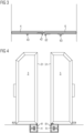
- Fig. 1 is a schematic cross-sectional view of an interior of a vehicle, in particular a passenger compartment of a rail vehicle for public transport.
- the interior has an aisle 2.
- the aisle 2 is bounded at the bottom by a floor 21, here a floor as part of an aisle for passengers of the vehicle, and laterally by a first side 22 and a second side 23 opposite the first side 22.
- the sides 22 and 23 can be parts of platforms in which devices or components of the vehicle are housed, for example, wheels of a chassis of the vehicle run in the platforms, and on which platforms seats can be arranged. Therefore, the floor of the vehicle above the platforms is also referred to as the seating level 10.
- the seating levels 10 are raised compared to the floor 21 of the aisle.
- the Figures 2 to 7 now illustrate a transition door device 1 according to the invention, which is arranged at least partially in the region of the corridor canyon 2.
- the transition door device 1 comprises an upper part 11 and a lower part 12, wherein the upper part 11 has two door leaves 3, 5 which can be moved in opposite directions between a closed state and an open state, a first movable door leaf 3 and a second door leaf 5 which can be moved in opposite directions to the first door leaf 3, and the lower part 12 has two door leaves 4, 6 which can be pivoted in opposite directions between a closed state and an open state, a first pivotable door leaf 4 and a second door leaf 6 which can be pivoted in opposite directions to the first door leaf 4.
- one door leaf 4, 6 is mechanically coupled with one door leaf 3, 5, the first door leaf 4 is mechanically coupled with the first door leaf 3 and the second door leaf 6 is mechanically coupled with the second door leaf 5 mechanically coupled.
- a sliding movement of the first door leaf 3 is converted into a pivoting movement of the first door leaf 5 and a sliding movement of the second door leaf 4 is converted into a pivoting movement of the second door leaf 6.
- first door leaf 4 is mechanically coupled to the first door leaf 3 in the area of the main closing edge 31 of the first door leaf 3 via a first pivot joint 42 in the area of the main closing edge 41 of the first door leaf 4.
- second door leaf 6 is mechanically coupled to the second door leaf 5 in the area of the main closing edge 51 of the second door leaf 5 via a second pivot joint 62 in the area of the main closing edge 61 of the second door leaf 6.
- first pivot arm 45 and a second pivot arm 65 are provided.
- the pivot arms 45, 65 are each arranged centrally between the main closing edges 41, 61 of the door leaves 4, 6 and the rear secondary closing edges 46, 66 of the door leaves 4, 6, which are opposite the main closing edges 41, 61 of the door leaves 4, 6, and are rotatably mounted on the respective door leaf 4, 6.
- the pivot arms 45, 65 are designed for rotatable mounting on the aisle channel 2 and are attached to the sides 22, 23 of the aisle channel 2.
- a first end of the pivot arms 45, 65 is connected to the door leaves 4, 6 via a pivot joint 43, 63, and a second end of the pivot arms 45, 65 is connected to the sides of the aisle channel via another pivot joint 44, 64.
- a four-link coupling mechanism here in the form of a sliding rocker, is designed, with the pivot arms 45, 65 as so-called sliding cranks and the respective sections of the door leaves 4, 6 between the articulated connections the respective pivot arms 43, 63 and the rotary joints 42, 62 as mechanical couplings with the door leaves 3, 5 as further gear elements.
- the door leaves 3, 5 and the door panels 4, 6 are each in a closed position and the first and second door leaves 3, 5 and the first and second door panels 4, 6 are in a common plane and the respective main closing edges 31, 41, 51, 61 as well as the upper secondary closing edges 48, 68 of the door panels 4, 6 and the lower secondary closing edges 37, 57 of the door leaves 3, 5 run flush with one another and lie against one another, forming a small gap.
- the upper secondary closing edges 38, 58 of the door leaves 3, 5, on the other hand, point towards the ceiling.
- the lower secondary closing edges 47, 67 of the door panels 4, 6 are opposite the floor 21 of the corridor canal 2.
- the two door leaves 3, 5 can be moved in opposite directions, essentially transverse to the corridor channel.
- the mechanical coupling via the pivot joints 42, 63 ensures that the door leaves 4, 6 are driven along.
- the main closing edges 41, 61 of the door leaves 4, 6 move along a path that is essentially parallel to the direction of movement of the door leaves 3, 5 or even coincides with it.
- the door leaves 3, 5 are approximately shifted out of the corridor and give the corridor to the passage through the transition door device 1.
- a small overlap can be accepted here, which is due to the mechanical coupling with the door leaves 4, 6.
- the door leaves 4, 6 are pivoted against the sides 22, 23 of the corridor canal 2, so that a sufficiently large passage width is achieved - the corridor is free for passage through the transition door device 1.
- the door leaves 4, 6 are aligned essentially parallel to the sides 22, 23 of the corridor 2 and are thus offset at an angle of approximately 90° to the door leaves.
- the vehicle may have an interior bulkhead (not shown here) with end walls on both sides, into which the door leaves 3, 5 are at least partially displaced or displaceable in the open position.
- the rear secondary closing edges 36, 56 of the door leaves 3, 5, opposite the respective main closing edges 31, 51 of the door leaves 3, 5, are then covered by the end walls at least on one side.
Landscapes
- Engineering & Computer Science (AREA)
- Mechanical Engineering (AREA)
- Support Devices For Sliding Doors (AREA)
Applications Claiming Priority (1)
| Application Number | Priority Date | Filing Date | Title |
|---|---|---|---|
| DE102023209499.1A DE102023209499B4 (de) | 2023-09-28 | 2023-09-28 | Übergangstürvorrichtung für ein großräumiges Fahrzeug mit Gangschlucht |
Publications (1)
| Publication Number | Publication Date |
|---|---|
| EP4530148A1 true EP4530148A1 (fr) | 2025-04-02 |
Family
ID=92926159
Family Applications (1)
| Application Number | Title | Priority Date | Filing Date |
|---|---|---|---|
| EP24202868.6A Pending EP4530148A1 (fr) | 2023-09-28 | 2024-09-26 | Dispositif de porte de transition pour un véhicule de grande taille avec fermeture de vitesse |
Country Status (2)
| Country | Link |
|---|---|
| EP (1) | EP4530148A1 (fr) |
| DE (1) | DE102023209499B4 (fr) |
Citations (5)
| Publication number | Priority date | Publication date | Assignee | Title |
|---|---|---|---|---|
| GB664862A (en) * | 1949-06-24 | 1952-01-16 | Arthur Charles Needs | Improvements in doors and entrances for passenger vehicles |
| FR2397299A1 (fr) | 1977-07-13 | 1979-02-09 | Sancereau Pierre | Porte coulissante pour caravane |
| US20090078824A1 (en) * | 2007-09-21 | 2009-03-26 | Chris Osborne | Paneled Partition |
| DE102013200071A1 (de) * | 2013-01-04 | 2014-07-10 | Siemens Aktiengesellschaft | Schienenfahrzeugtür |
| DE102023200487A1 (de) | 2023-01-23 | 2024-07-25 | Siemens Mobility GmbH | Innenschiebetür für ein Schienenfahrzeug mit einfahrbarer Abdeckung |
Family Cites Families (1)
| Publication number | Priority date | Publication date | Assignee | Title |
|---|---|---|---|---|
| US10023288B2 (en) * | 2012-10-30 | 2018-07-17 | Honda Patents & Technologies North America, Llc | Aircraft door mechanism with handle actuated descender |
-
2023
- 2023-09-28 DE DE102023209499.1A patent/DE102023209499B4/de active Active
-
2024
- 2024-09-26 EP EP24202868.6A patent/EP4530148A1/fr active Pending
Patent Citations (5)
| Publication number | Priority date | Publication date | Assignee | Title |
|---|---|---|---|---|
| GB664862A (en) * | 1949-06-24 | 1952-01-16 | Arthur Charles Needs | Improvements in doors and entrances for passenger vehicles |
| FR2397299A1 (fr) | 1977-07-13 | 1979-02-09 | Sancereau Pierre | Porte coulissante pour caravane |
| US20090078824A1 (en) * | 2007-09-21 | 2009-03-26 | Chris Osborne | Paneled Partition |
| DE102013200071A1 (de) * | 2013-01-04 | 2014-07-10 | Siemens Aktiengesellschaft | Schienenfahrzeugtür |
| DE102023200487A1 (de) | 2023-01-23 | 2024-07-25 | Siemens Mobility GmbH | Innenschiebetür für ein Schienenfahrzeug mit einfahrbarer Abdeckung |
Also Published As
| Publication number | Publication date |
|---|---|
| DE102023209499A1 (de) | 2025-04-03 |
| DE102023209499B4 (de) | 2025-05-22 |
Similar Documents
| Publication | Publication Date | Title |
|---|---|---|
| DE60218365T2 (de) | Gelenkvorrichtung für ein Flugzeugtürblatt und Flugzeugtür mit einer solchen Vorrichtung | |
| DE102016202395B3 (de) | Personenkraftfahrzeug mit einer Seitentür | |
| WO2001042604A1 (fr) | Paroi coulissante comportant plusieurs elements de paroi pouvant coulisser lateralement | |
| EP3900982A1 (fr) | Système d'entrée pourvu de rabat d'étanchéité accessible | |
| DE202015007818U1 (de) | Aufhangungsanordnung für eine Fahrzeugtür eines Fahrzeugs, Fahrzeugtür welche mittels einer Aufhängungsanordnung an einem Fahrzeug aufgehängt ist sowie Fahrzeug mit einer Fahrzeugtür, die mit einer derartigen Aufhängungsanordnung am Fahrzeug aufgehängt ist | |
| DE102004036184A1 (de) | Flugzeugtür-Anordnung mit einer um 180° schwenkenden Flugzeugtür | |
| EP3213973B1 (fr) | Dispositif pour monter dans un vehicule | |
| EP3663158B1 (fr) | Porte coulissante à basculement avec système de marche pour un véhicule | |
| EP3400159B1 (fr) | Dispositif porte et procédé de fonctionnement d'un dispositif porte | |
| EP3684667B1 (fr) | Véhicule ferroviaire comprenant un élément de sol mobile au niveau de l'ouverture de la porte | |
| EP1536999B1 (fr) | Vehicule sur rails pourvu d'une sortie de secours sur la face avant | |
| DE102016201275B3 (de) | Frontnotausstieg | |
| EP1669231A2 (fr) | Porte coulissante et pliante pour véhicules automobiles | |
| AT12418U1 (de) | Schwenkschiebetürsystem für fahrzeuge | |
| DE102023209499B4 (de) | Übergangstürvorrichtung für ein großräumiges Fahrzeug mit Gangschlucht | |
| EP3812234A1 (fr) | Passerelle pour un véhicule de transport de personnes et véhicule de transport de personnes | |
| DE69103056T2 (de) | Vorrichtung und Verfahren für die Öffnung von Aufzugstüren. | |
| DE2330900A1 (de) | Vorrichtung zum abstuetzen, sowie zum oeffnen und schliessen von fahrzeug-tueren | |
| DE19734752A1 (de) | Schiebedrehtür | |
| EP4021365B1 (fr) | Structure de porte de véhicule à rampe intégrée | |
| DE60224333T2 (de) | Fahrerkabine einer Baumaschine mit einer Vorrichtung zum Öffnen und Schliessen einer Tür, und Baumaschine mit einer solchen Fahrerkabine | |
| EP0088101B1 (fr) | Porte pivotante-coulissante pour vehicule | |
| WO2021239366A1 (fr) | Dispositif de porte à deux battants pour un véhicule | |
| DE102023125043B4 (de) | System zum Öffnen einer Öffnung einer Tür | |
| EP1328430B1 (fr) | Dispositif superieur de mise en place de cloisons amovibles de wagons a marchandises |
Legal Events
| Date | Code | Title | Description |
|---|---|---|---|
| PUAI | Public reference made under article 153(3) epc to a published international application that has entered the european phase |
Free format text: ORIGINAL CODE: 0009012 |
|
| STAA | Information on the status of an ep patent application or granted ep patent |
Free format text: STATUS: THE APPLICATION HAS BEEN PUBLISHED |
|
| AK | Designated contracting states |
Kind code of ref document: A1 Designated state(s): AL AT BE BG CH CY CZ DE DK EE ES FI FR GB GR HR HU IE IS IT LI LT LU LV MC ME MK MT NL NO PL PT RO RS SE SI SK SM TR |
|
| STAA | Information on the status of an ep patent application or granted ep patent |
Free format text: STATUS: REQUEST FOR EXAMINATION WAS MADE |
|
| RAP3 | Party data changed (applicant data changed or rights of an application transferred) |
Owner name: SIEMENS MOBILITY GMBH |
|
| 17P | Request for examination filed |
Effective date: 20250919 |