EP4530181A1 - Flugzeug, flugzeugsteuerungsverfahren und -vorrichtung und computerlesbares speichermedium - Google Patents
Flugzeug, flugzeugsteuerungsverfahren und -vorrichtung und computerlesbares speichermedium Download PDFInfo
- Publication number
- EP4530181A1 EP4530181A1 EP22943025.1A EP22943025A EP4530181A1 EP 4530181 A1 EP4530181 A1 EP 4530181A1 EP 22943025 A EP22943025 A EP 22943025A EP 4530181 A1 EP4530181 A1 EP 4530181A1
- Authority
- EP
- European Patent Office
- Prior art keywords
- aircraft
- rotor assemblies
- state
- rotor
- vehicle body
- Prior art date
- Legal status (The legal status is an assumption and is not a legal conclusion. Google has not performed a legal analysis and makes no representation as to the accuracy of the status listed.)
- Pending
Links
Images


Classifications
-
- B—PERFORMING OPERATIONS; TRANSPORTING
- B64—AIRCRAFT; AVIATION; COSMONAUTICS
- B64C—AEROPLANES; HELICOPTERS
- B64C27/00—Rotorcraft; Rotors peculiar thereto
- B64C27/22—Compound rotorcraft, i.e. aircraft using in flight the features of both aeroplane and rotorcraft
- B64C27/26—Compound rotorcraft, i.e. aircraft using in flight the features of both aeroplane and rotorcraft characterised by provision of fixed wings
-
- B—PERFORMING OPERATIONS; TRANSPORTING
- B64—AIRCRAFT; AVIATION; COSMONAUTICS
- B64C—AEROPLANES; HELICOPTERS
- B64C27/00—Rotorcraft; Rotors peculiar thereto
- B64C27/52—Tilting of rotor bodily relative to fuselage
-
- B—PERFORMING OPERATIONS; TRANSPORTING
- B64—AIRCRAFT; AVIATION; COSMONAUTICS
- B64C—AEROPLANES; HELICOPTERS
- B64C27/00—Rotorcraft; Rotors peculiar thereto
- B64C27/20—Rotorcraft characterised by having shrouded rotors, e.g. flying platforms
-
- B—PERFORMING OPERATIONS; TRANSPORTING
- B64—AIRCRAFT; AVIATION; COSMONAUTICS
- B64C—AEROPLANES; HELICOPTERS
- B64C27/00—Rotorcraft; Rotors peculiar thereto
- B64C27/22—Compound rotorcraft, i.e. aircraft using in flight the features of both aeroplane and rotorcraft
- B64C27/28—Compound rotorcraft, i.e. aircraft using in flight the features of both aeroplane and rotorcraft with forward-propulsion propellers pivotable to act as lifting rotors
-
- B—PERFORMING OPERATIONS; TRANSPORTING
- B64—AIRCRAFT; AVIATION; COSMONAUTICS
- B64C—AEROPLANES; HELICOPTERS
- B64C29/00—Aircraft capable of landing or taking-off vertically, e.g. vertical take-off and landing [VTOL] aircraft
- B64C29/0008—Aircraft capable of landing or taking-off vertically, e.g. vertical take-off and landing [VTOL] aircraft having its flight directional axis horizontal when grounded
- B64C29/0016—Aircraft capable of landing or taking-off vertically, e.g. vertical take-off and landing [VTOL] aircraft having its flight directional axis horizontal when grounded the lift during taking-off being created by free or ducted propellers or by blowers
- B64C29/0025—Aircraft capable of landing or taking-off vertically, e.g. vertical take-off and landing [VTOL] aircraft having its flight directional axis horizontal when grounded the lift during taking-off being created by free or ducted propellers or by blowers the propellers being fixed relative to the fuselage
-
- B—PERFORMING OPERATIONS; TRANSPORTING
- B64—AIRCRAFT; AVIATION; COSMONAUTICS
- B64C—AEROPLANES; HELICOPTERS
- B64C29/00—Aircraft capable of landing or taking-off vertically, e.g. vertical take-off and landing [VTOL] aircraft
- B64C29/0008—Aircraft capable of landing or taking-off vertically, e.g. vertical take-off and landing [VTOL] aircraft having its flight directional axis horizontal when grounded
- B64C29/0016—Aircraft capable of landing or taking-off vertically, e.g. vertical take-off and landing [VTOL] aircraft having its flight directional axis horizontal when grounded the lift during taking-off being created by free or ducted propellers or by blowers
- B64C29/0033—Aircraft capable of landing or taking-off vertically, e.g. vertical take-off and landing [VTOL] aircraft having its flight directional axis horizontal when grounded the lift during taking-off being created by free or ducted propellers or by blowers the propellers being tiltable relative to the fuselage
Definitions
- the present disclosure generally relates to the field of aircrafts, and, more particularly, to an aircraft, an aircraft control method and device, and a computer-readable storage medium.
- An aircraft configuration adopated and used by existing vertical take-off/landing aircrafts is generally a conventional layout.
- An aircraft with the conventional layout has better stability and includes main wings and a relatively large horizontal tail.
- the horizontal tail of the aircraft with the conventional layout does not produce lift thrust in the cruising state, but produces a negative lift thrust to balance the aircraft. Therefore, it will increase the induced drag of the main wings, hence reducing the efficiency of level flight of the aircraft.
- the present disclosure provides an aircraft, an aircraft control method and device, and a computer-readable storage medium, to alleviate the above problem.
- the aircraft includes: a vehicle body; main wings, fixedly connected to the vehicle body and used to provide lift thrust for the aircraft; canards, arranged at the vehicle body near a nose and used to provide the lift thrust for the aircraft; and a multi-rotor assembly including first rotor assemblies and second rotor assemblies.
- the first rotor assemblies are mechanically coupled with the main wings; and the second rotor assemblies and the canards are rotatably connected to each other.
- the second rotor assemblies are configured to be able to adjust their tilting angle relative to the canards to provide lift thrust and/or forward pulling thrust for the aircraft.
- the aircraft includes: a vehicle body; main wings, fixedly connected to the vehicle body and used to provide lift thrust for the aircraft; and a multi-rotor assembly including first rotor assemblies.
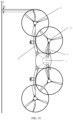
- the first rotor assemblies When the aircraft is in a level flight state, the first rotor assemblies generate a forward pulling thrust, and a side of a propeller disk plane of the first rotor assembly away from the vehicle body at least partially overlaps with a projection of a wing tip of the main wings to a normal plane of the roll axis of the aircraft.
- the aircraft includes: a vehicle body; main wings, fixedly connected to the vehicle body and used to provide lift thrust for the aircraft; canards, arranged at the vehicle body near a nose and used to provide the lift thrust for the aircraft; and a multi-rotor assembly including first rotor assemblies and second rotor assemblies.
- the first rotor assemblies are mechanically coupled with the main wings; and the second rotor assemblies and the canards are rotatably connected to each other.
- the method includes: when the aircraft is in a hovering state, a vertical take-off state, or a vertical descent state, controlling the tilting angle of the second rotor assemblies to be a preset upper limit angle of the tilting angle of the second rotor assemblies; and when the aircraft is in a level flight state, controlling the tilting angle of the second rotor assemblies to be a preset lower limit angle of the tilting angle of the second rotor assemblies.
- the control device includes a memory for storing executable instructions and one or more processors. When the one or more processors execute the executable instructions, any method provided by the present disclosure is executed.
- the computer-readable storage medium is configured to store executable instructions. When the executable instructions are executed by a processor, any method provided by the present disclosure is executed.
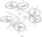
- the present disclosure provides an aircraft 10.
- the aircraft 10 may be an aircraft 10, a manned aircraft 10, a logistics aircraft 10, etc.
- the aircraft 10 includes a vehicle body 11; main wings 12 which are fixedly connected to the vehicle body 11 and used to provide lift thrust for the aircraft 10; canards 13 which are disposed at the vehicle body 11 close to a nose and used to provide lift thrust for the aircraft 10, and a multi-rotor assembly including first rotor assemblies 141 and second rotor assemblies 142.
- the first rotor assemblies 141 are mechanically coupled to the main wings 12, and the second rotor assemblies 142 are rotatably connected to the canards 13.
- the second rotor assemblies 142 may provide lift thrust or forward pull thrust to the aircraft 10 according to tilting angles of the second rotor assemblies 142.
- both the canards 13 with a canard layout and the main wings 12 may both generate lift thrust.
- the maximum lift coefficient and lift-drag ratio that are better than those of the conventional layout may be obtained.
- Increasing the maximum lift coefficient may reduce the transition process time and may also reduce the energy required for the transition process.
- Increasing the lift-to-drag ratio may increase the aircraft's range and reduce the aircraft's weight.
- the first rotor assemblies 141 may include motors and propellers coupled to each other, and the motors may be used to drive the propellers to rotate to provide flight control thrust for the aircraft 10.
- the second rotor assemblies 142 may include motors and propellers coupled to each other, and the motors may be used to drive the propellers to rotate to provide flight control thrust for the aircraft 10.
- the first rotor assemblies 141 may be rotatably connected to the main wings 12.
- the first rotor assemblies 141 may provide lift and/or forward pull thrust for the aircraft 10 according to the tilting angle of the first rotor assemblies 141.
- the aircraft 10 further includes a first tilting mechanism 15, and the first rotor assemblies 141 are tiltably connected to the main wings 12 through the first tilting mechanism 15.
- the aircraft 10 includes a second tilting mechanism 16, and the second rotor assemblies 142 are tiltably connected to the canards 13 through the second tilting mechanism 16.
- the canards 13 are fixedly connected to the vehicle body 11.
- the second rotor assemblies 142 are tiltable relative to the canards 13, and are rotatably connected to the canards 13 and the vehicle body 11.
- the embodiments of the present disclosure may improve the stability of the aircraft performance and reduce the energy consumption caused by the need to tilt the canards 13 and the second rotor assemblies 142.
- the main wings 12 may be disposed near the tail of the vehicle body 11, and the center of gravity of the vehicle body 11 may be located between the main wings 12 and the canards 13.
- the first rotor assemblies 141 may be disposed at the outer wing sections of the main wings 12, and the second rotor assemblies 142 may be disposed at the wing tips of the canards 13.
- the reasonable rotor rotation direction may suppress the wing tip vortex to improve the aerodynamic efficiency of the entire machine.
- the yaw axis (Y in the drawings), the roll axis (R in the drawings), and the pitch axis (P in the drawings) described in the present disclosure are defined in the body axis system, as shown in FIG. 1 .
- the propeller disk plane of the first rotor assembly 141 may be substantially parallel to the pitch axis (P in the drawings) of the aircraft 10; and/or, the propeller disk plane of the second rotor assembly 142 may be substantially parallel to the pitch axis (P in the drawings) of the aircraft 10.
- the propeller disk plane may be a plane formed by the rotor propellers rotating when the aircraft 10 is flying.
- the propeller disk plane of the first rotor assembly 141 may be substantially parallel to a plane formed by the pitch axis (P in the drawings) and the roll axis (R in the drawings) of the aircraft 10; and/or, the propeller disk plane of the second rotor assembly 142 may be substantially parallel to a plane formed by the pitch axis (P in the drawings) and the roll axis (R in the drawings) of the aircraft 10.
- the propeller disk plane of the first rotor assembly 141 may be substantially perpendicular to the roll axis (R in the drawings) of the aircraft 10; and/or, the propeller disk plane of the second rotor assembly 142 may be substantially parallel to the pitch axis (P in the drawings) of the aircraft 10.
- the propeller disk plane of the first rotor assembly 141 may be substantially parallel to a plane formed by the pitch axis (P in the drawings) and the roll axis (R in the drawings) of the aircraft 10; and/or, the propeller disk plane of the second rotor assembly 142 may be substantially parallel to a plane formed by the pitch axis (P in the drawings) and the roll axis (R in the drawings) of the aircraft 10.
- the level flight state may include a horizontal flight state.
- the flight speed of the aircraft 10 may be in a constant speed state or a variable speed state.
- the tilting angle of the first rotor assemblies 141 is a preset upper limit angle of the tilting angle of the first rotor assemblies 141; and/or, the tilting angle of the second rotor assemblies 142 is the preset upper limit angle of the tilting angle of the second rotor assemblies 142.
- the tilting angle of the first rotor assemblies 141 is a preset lower limit angle of the tilting angle of the first rotor assemblies 141; and/or, the tilting angle of the second rotor assemblies 142 is the preset lower limit angle of the tilting angle of the second rotor assemblies 142.
- the tilting angle may be the angle of the first rotor assemblies 141 or the second rotor assemblies 142 relative to the pitch axis (P in the drawings) of the aircraft 10.
- the preset upper limit angle and the preset lower limit angle may be the two limit end points of the tilting angle, that is, the first rotor assemblies 141 and/or the second rotor assemblies 142 may be only able to rotate between the two limit points.
- the preset upper limit angle of the tilting angle of the first rotor assemblies 141 is 0 degrees
- the preset lower limit angle is 90 degrees.
- the preset upper limit angle of the tilting angle of the first rotor assemblies 141 may be the same as or different from the preset upper limit angle of the tilting angle of the second rotor assemblies 142.
- the preset lower limit angle of the tilting angle of the first rotor assemblies 141 may be the same as or different from the preset lower limit angle of the tilting angle of the second rotor assemblies 142.
- the tilting angle of the first rotor assemblies 141 and the tilting angle of the second rotor assemblies 142 switch from an equal state to an unequal state.
- the tilting angle of the first rotor assemblies 141 and the tilting angle of the second rotor assemblies 142 change from an equal state to an unequal state.
- the tilting angle of the first rotor assemblies 141 and the tilting angle of the second rotor assemblies 142 switch from an equal state to an unequal state.
- the difference between the first flight state and the second flight state may include one or more of a difference in flight speed, a difference in flight altitude, a difference in flight conditions, or a difference in flight attitude.
- the difference between the tilting angle of the first rotor assemblies 141 and the tilting angle of the second rotor assemblies 142 may be larger than zero.
- the multi-rotor assembly further includes third rotor assemblies 143, and the third rotor assemblies 143 may be connected to the vehicle body 11 or the main wings 12.
- the third rotor assemblies 143 may include motors and propellers coupled to each other. The motors are used to drive the propellers to rotate to generate thrust acting on the aircraft 10.
- Each of the first rotor assemblies 141, the second rotor assemblies 142 and the third rotor assemblies 143 may include two rotor members symmetrically distributed.
- the propeller disk plane of the third rotor assembly 143 may be located above the main wings 12 or the vehicle body 11, reducing the risk of injury caused by the propeller disk plane being located below the main wings 12 or the vehicle body 11.
- the propeller disk plane of the third rotor assembly 143 may be parallel to the vehicle body 11, and the third rotor assemblies 143 may be in a working state.
- the layout of six rotor assemblies may effectively resist the power imbalance problem caused by the failure of a single engine. After any engine failure, it may be ensured that the entire aircraft has capabilities to complete level flight and hovering. In the transitional state, switching to a hover configuration may be achieved immediately for a vertical landing in response to a single engine failure.
- the third rotor assemblies 143 When the aircraft 10 is in the level flight state, the third rotor assemblies 143 may be in a stalled state. In the embodiments of the present disclosure, by controlling the third rotor assemblies 143 to be in the stalled state for the level flight state, forward flight power redundancy may be reduced and the endurance of the aircraft 10 may be improved.
- the blades of the third rotor assemblies 143 may extend along the roll axis direction of the aircraft 10.
- the blades When the aircraft 10 is in the level flight state, the blades of the third rotor assemblies 143 may extend along the roll axis direction of the aircraft 10.
- they When the blades extend along the direction of the roll axis (R in the illustration) of the aircraft 10, they may be kept in a phase along the airflow to reduce the resistance of forward flight.
- the third rotor assemblies 143 may be connected to the main wings 12 through a nacelle structure, or the third rotor assemblies 143 may be connected to the main wings 12 through a tail boom 18.
- a vertical tail 19 is provided at the tail boom 18 to increase the stability of the heading.
- the vertical fin 19 may be provided with a rudder to increase the heading control capability.
- the propeller disk plane of the third rotor assembly 143 and the propeller disk plane of the second rotor assembly 142 may be substantially symmetrical along the direction of the aircraft 10.
- the rotating speeds of the first rotor assemblies 141, the second rotor assemblies 142, and the third rotor assemblies 143 may be controlled according to the weight distribution of the aircraft 10, the shape of the vehicle body 11, etc., to make the vehicle body 11 maintain a horizontally stable state.
- the blades of the third rotor assemblies 143 may be stored in the cavity of the nacelle structure to avoid flight resistance caused by protrusion of the blades, and the airflow disturbance in forward flight may be smaller.
- the first rotor assemblies may generate a forward pulling thrust, and a side of the propeller disk plane of the first rotor assembly 141 away from the vehicle body 11 at least partially overlaps with the projection of the wing tip of the main wings 12 on the normal plane S1 of the roll axis (R in the drawings).
- one or more of the first rotor assemblies 141, the second rotor assemblies 142 or the third rotor assemblies 143 may have an outward thrust component m along the pitch axis (P in the drawings) of the aircraft 10.
- the pulling thrust line of the multi-rotor assembly may have an outward tilting tendency to ensure that it has a considerable heading control torque in the hovering configuration to meet the maneuverability requirements.
- the angle a of one or more of the first rotor assemblies 141, the second rotor assemblies 142 or the third rotor assemblies 143 with respect to the pitch axis (P in the drawings) of the aircraft 10 may be larger than 0.
- the pulling thrust line of the multi-rotor assembly may have an outward tilting tendency to ensure that it has a considerable heading control torque in the hovering configuration to meet the maneuverability requirements.
- the propeller disk planes of one or more of the first rotor assemblies 141, the second rotor assemblies 142 or the third rotor assemblies 143 may tilt toward a direction away from the vehicle body along the pitch axis (P in the drawings) of the aircraft 10.
- the pulling thrust line of the multi-rotor assembly may have an outward tilting tendency to ensure that it has a considerable heading control torque in the hovering configuration to meet the maneuverability requirements.
- the canards 13 may be provided with first flaps 131, and the first flaps 131 may be used to provide a pitch torque to the aircraft 10.
- the first flaps 131 may be movable relative to the canards 13 to keep the aircraft 10 level.
- the main wings 12 may be provided with ailerons 121, and the ailerons 121 are used to provide a rolling torque for the aircraft 10.
- the ailerons 121 may be movable relative to the main wings 12 to keep the aircraft 10 level.
- the third rotor assemblies 143 may still keep working, but as the flight speed gradually increases, their propulsion gradually decreases.
- the aerodynamic pressure gradually increases, and the longitudinal and lateral control capabilities of the ailerons121 and the first flaps 131 may gradually increase.
- the control weight of the ailerons 121 and the elevator flap may gradually be added in the control algorithm, to cooperate the thrust control of the three rotor assemblies to achieve aircraft state control that meets flight quality requirements.
- the ailerons 121 may be responsible for generating the roll torque of the aircraft, and may be used to assist in generating the roll control torque, and may also offset the roll torque generated by the coupling of the output of the yaw control torque, thereby balancing the aircraft 10.
- the first flaps 131 may be responsible for generating the pitch torque of the aircraft. When their trailing edges are tilted upward, the lift propulsion generated by the canards 13 may be reduced to generate a nose-down torque. When their trailing edges are tilted downward, the lift propulsion generated by the canard 13 may be increased to generate a nose-up torque, thereby balancing the aircraft 10.
- the additional control torque generated by the manipulation of the first flaps 131 may be used to assist the pitch control of the aircraft 10 in the first transition stage, and may also compensate for the insufficient nose-up torque generated by the tilting of the second rotor assemblies 142.
- the first rotor assemblies 141 and/or the second rotor assemblies 142 may provide forward pulling thrust for the aircraft 10 to increase the flight speed of the aircraft 10.
- the flight speed is larger than the preset speed, it may be determined that the aircraft 10 enters the level flight state.
- the pulling thrust lines of the first rotor assemblies 141 and the second rotor assemblies 142 may be parallel to the roll axis (R in the drawings) and the pitch axis (P in the drawings) of the unmanned aircraft.
- the first rotor assemblies 141 and/or the second rotor assemblies 142 may provide backward resistance for the aircraft 10 to reduce the flight speed of the aircraft 10.
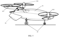
- the vehicle body 11 may be provided with a ventral fin 20 near the tail.
- the ventral fin 20 may be rotatable relative to the vehicle body 11 to adapt to different flight states of the aircraft 10.
- the vehicle body 11 may be provided with a landing gear 17 near the nose.
- the landing gear may be fixedly connected to the vehicle body 11. Or, as shown in FIG. 5 , the landing gear may be movable relative to the vehicle body 11 and may be a retractable landing gear 17.
- the ventral fin 20 when the aircraft 10 is not in flight, may be in contact with the ground and form a layout of a three-point landing gear 17 with the landing gear 17.
- the aircraft 10 may further include a torque adjustment mechanism.
- the torque adjustment mechanism may be connected to the first rotor assemblies 141 and/or the second rotor assemblies 142, for adjusting pitch angles of the blades of the first rotor assemblies 141 and/or the second rotor assemblies 142.
- the present disclosure also provides another aircraft 10 shown in FIG. 10 .
- the aircraft 10 includes a vehicle body 11, main wings 12 fixedly connected to the vehicle body 11 and used to provide lift propulsion for the aircraft 10, and a multi-rotor assembly.
- the multi-rotor assembly includes first rotor assemblies 141.
- the first rotor assemblies 141 may generate a forward pulling thrust, and a side of the propeller disk plane of the first rotor assembly 141 away from the vehicle body 11 may at least partially overlaps with the projection of the wing tips of the main wings 12 on the normal plane S1 of the roll axis (R in the drawings).
- the overlapping part is x.
- the side of the propeller disk plane of the first rotor assembly 141 away from the vehicle body 11 may include a one-tenth part of the propeller disk plane away from the vehicle body 11.
- One wing tip of the main wings 12 may include a 100th part of the main wings 12 away from the vehicle body 11.
- a distance K between the farthest end of the propeller disk plane of the first rotor assembly 141 away from the vehicle body 11 and the projection of a farthest end of the wing tip of the main wings 12 to the normal plane S1 of the roll axis (R in the drawings) is less than the preset distance.
- the farthest end of the propeller disk plane of the first rotor assembly 141 away from the vehicle body 11 and the projection of the farthest end of the wing tip of the main wings 12 to the normal plane S1 of the roll axis (R in the drawings) may be substantially overlap.
- the preset distance may be 0.01 of the length of the main wing.
- the first rotor assemblies 141 may generate the forward pulling thrust, and there may be a certain moment during the rotation of the blades of the first rotor when the blade tips of the blades substantially overlap with the farthest ends of the wing tips away from the vehicle body.
- the aspect ratio may be increased and flight efficiency may be improved.
- the propeller tip vortex may be suppressed to improve the aerodynamic efficiency of the entire machine.
- the aircraft 10 may include a first tilting mechanism 15, and the first rotor assemblies 141 may be tiltably connected to the main wings 12 through the first tilting mechanism 15.
- the propeller disk plane of the first rotor assembly 141 may be substantially parallel to the pitch axis (P in the drawings) of the aircraft 10.
- the propeller disk plane of the first rotor assembly 141 may be substantially perpendicular to the roll axis (R in the drawings) of the aircraft 10.
- the first rotor assemblies 141 may have an outward thrust component m along the pitch axis (P in the drawings) of the aircraft 10.
- the angle between the propeller disk plane of the first rotor assembly 141 and the pitch axis (P in the drawings) of the aircraft 10 may be larger than zero.
- one or more of the propeller disk plane of the first rotor assembly 141, the propeller disk plane of the second rotor assembly 142, or the propeller disk plane of the third rotor assembly 143 may be tilted away from the vehicle body along the pitch axis (P in the drawings) of the aircraft 10.
- the main wings 12 may be provided with ailerons 121, and the ailerons 121 may be used to provide a rolling torque for the aircraft 10.
- the main wings 12 may be provided with second flaps 122, and the second flaps 122 may be used to reduce the flight speed of the aircraft 10.
- the vehicle body 11 may be provided with a ventral fin 20 near the tail.
- the ventral fin 20 may be rotatable relative to the vehicle body 11.
- the aircraft 10 may further include a torque adjustment mechanism.
- the torque adjustment mechanism may be connected to the first rotor assemblies 141, for adjusting pitch angles of the blades of the first rotor assemblies 141 and/or the second rotor assemblies 142.
- the present disclosure also provides a control method of an aircraft 10.
- the aircraft 10 includes a vehicle body 11; main wings 12 which are fixedly connected to the vehicle body 11 and are used to provide lift propulsion for the aircraft 10; canards 13 which are disposed at the vehicle body 11 close to the nose and used to provide lift propulsion for the aircraft 10, and a multi-rotor assembly including first rotor assemblies 141 and second rotor assemblies 142.
- the first rotor assemblies 141 may be mechanically coupled to the main wings 12, and the second rotor assemblies 142 may be rotatably connected to the canards 13.
- the control method may include: when the aircraft 10 is in the hovering state, the vertical takeoff state, or the vertical descending state, controlling the tilting angle of the second rotor assemblies 142 to be a preset upper limit angle of the tilting angle of the second rotor assemblies 142; when the aircraft 10 is in the level flight state, controlling the tilting angle of the second rotor assemblies 142 to be a preset lower limit angle of the tilting angle of the second rotor assemblies 142.
- control method provided by the embodiments of the present disclosure may be applied to any aircraft 10 provided by any embodiments of the present disclosure.
- the control method may include: controlling the movement of the second flaps 122 relative to the main wings 12 to increase the flight resistance of the aircraft 10, thereby reducing the flight speed of the aircraft.
- first rotor assemblies 141 may be rotatably connected to the main wings 12.
- the method may further include:
- the vertical take-off state or the vertical descending state
- controlling the tilting angle of the second rotor assemblies 142 to be a preset upper limit angle of the tilting angle of the second rotor assemblies 142
- controlling the tilting angle of the second rotor assemblies 142 to be a preset lower limit angle of the tilting angle of the second rotor assemblies 142.
- the method may further include: when the aircraft 10 is in the first transition state from the hovering state to the level flight state, controlling the operating parameters of the first rotor assemblies 141 and/or the second rotor assemblies 142 to increase the flight speed of the aircraft 10.
- the method may further include: when the aircraft 10 is in the second transition state from the level flight state to the hovering state, controlling the operating parameters of the first rotor assemblies 141 and/or the second rotor assemblies 142 to provide backward resistance for the aircraft 10 to reduce the flight speed of the aircraft 10.
- the forward pulling thrust may become less than the backward resistance, to reduce the flight speed of the aircraft 10.
- the flight speed of the aircraft 10 may be reduced by reducing the tilting angle of the first rotor assemblies 141 and/or the second rotor assemblies 142 such that the forward pulling thrust is less than the backward resistance.
- the aircraft configurations in the second transition state may be similar to the aircraft configurations in the first transition state.
- the difference may be that the corresponding relationship between the flight speed and the tilting angle of the first rotor assemblies 141 and the second rotor assemblies 142 are different.
- the method may further include: controlling the operating parameters of the first rotor assemblies 141 and/or the second rotor assemblies 142 according to the current attitude and flight speed of the aircraft 10, to enable the aircraft 10 to fly stably.
- the operating parameters of the first rotor assemblies 141 may include one or more of tilting angle, rotation speed, and attack angle of the blades; and the operating parameters of the second rotor assemblies 142 may include one or more of tilting angle, rotation speed, and attack angle of the blades.
- the method may further include: when the aircraft 10 transitions from the first flight state to the second flight state, controlling the tilting angle of the first rotor assemblies 141 and the tilting angle of the second rotor assemblies 142 to switch from an equal state to an unequal state.
- the method may further include: exemplarily, at one certain moment when the aircraft 10 has a horizontal forward flight speed, the difference between the tilting angle of the first rotor assemblies 141 and the tilting angle of the second rotor assemblies 142 is larger than zero.
- the multi-rotor assembly may further include third rotor assemblies 143 connected to the vehicle body 11 or the main wings 12.
- the method may include: when the aircraft 10 is in the level flight state, controlling the first rotor assemblies 141 to be in a stalled state.
- the canards13 may be provided with first flaps 13.
- the method may further include: when the aircraft 10 is in the first transition state from the hovering state to the level flight state, according to the current flight state of the aircraft 10, controlling the first flaps 131 to move relative to the canard to keep the aircraft 10 level.
- the main wings 12 may be provided with ailerons 121.
- the ailerons 121 may be controlled to move relative to the main wings 12, to keep the aircraft 10 level.
- the first rotor assemblies 141 and the second rotor assemblies 142 may be controlled to tilt forward simultaneously to provide thrust for forward acceleration.
- the tilting angle of the first rotor assemblies 141 may be ⁇ _1
- the tilting angle of the second rotor assemblies 142 may be ⁇ _2. It can be clearly seen from the angle relationship in the figure that the tilting angle in the hovering state is 0 and the tilting angle in the level flight state is approximately 90 degrees.
- the third rotor assemblies 143 may still keep working, but as the flight speed gradually increases, its thrust may gradually decrease.
- the aerodynamic pressure may gradually increase, and the longitudinal and lateral control capabilities of the ailerons 121 and elevator flaps may gradually increase.
- the control weights of the ailerons 121 and elevator flaps may gradually increase, to cooperate with the thrust control of the first rotor assemblies 141, the second rotor assemblies 142 and the third rotor assemblies 143 to achieve aircraft state control that meets flight quality requirements.
- the ailerons 121 may be responsible for generating the roll torque of the aircraft. It may be used to assist in generating the roll control torque, and may also offset the roll torque generated by the coupling of the output of the yaw control torque.
- the first flaps 131 may be responsible for generating the pitching torque of the aircraft.
- the lift thrust generated by the canards 13 may be reduced to generate a nose-down torque.
- the lift thrust of the canards 13 may be increased to produce head-up torque.
- the additional control torque generated by the manipulation of the first flaps 131 may be used to assist the pitch control of the aircraft in the transition stage, and may also make up for the lack of nose-up torque generated by the tilting of the first rotor assemblies 141.
- the pitch angle of the blades (1411, 1421) of the first rotor assemblies 141 and/or the second rotor assemblies 142 may be adjusted to adjust the pulling thrust through torque variation.
- the torque and rotation speed may also be controlled simultaneously to adjust the pulling thrust.
- FIG. 13(1) shows the state of the blades (1411, 1421) in the level flight state
- FIG. 13(2) shows the state of the blades (1411, 1421) in the hovering state.
- the rotation speed of each rotor member in the first rotor assemblies 141 and the second rotor assemblies 142 may also be controlled to generate a thrust difference, thereby controlling the flight attitude of the aircraft 10.
- the first flaps 131, the ailerons 121 and the second flaps 122 may be controlled to stop working. Only six rotor members may be used for attitude control, and other rudder surfaces may not participate in the torque output required by the aircraft 10.
- the vehicle body 11 of the aircraft 10 may be provided with a ventral fin 20 near the tail.
- the ventral fin 20 may be controlled to rotate relative to the vehicle body 11.
- the ventral fin 20 may rotate relative to the vehicle body 11 to improve heading stability adaptability.
- the ventral fin 20 may rotate relative to the vehicle body 11 to improve the stability of the aircraft 10.
- the difference between the first flight state and the second flight state may include one or more of a difference in flight speed, a difference in flight altitude, a difference in flight conditions, and a difference in flight attitude.
- the present disclosure also provides a memory for storing executable instructions and one or more processors.
- the one or more processors execute the executable instructions, the control method provided by previous embodiments of the present disclosure may be implemented.
- the present disclosure also provides a computer-readable storage medium.
- the computer-readable storage medium may be used to store executable instructions. When the executable instructions are executed by a processor, the control method provided by previous embodiments of the present disclosure may be implemented.
Landscapes
- Engineering & Computer Science (AREA)
- Aviation & Aerospace Engineering (AREA)
- Mechanical Engineering (AREA)
- Chemical & Material Sciences (AREA)
- Combustion & Propulsion (AREA)
- Toys (AREA)
Applications Claiming Priority (1)
| Application Number | Priority Date | Filing Date | Title |
|---|---|---|---|
| PCT/CN2022/094545 WO2023225819A1 (zh) | 2022-05-23 | 2022-05-23 | 飞行器、飞行器的控制方法及装置、计算机可读存储介质 |
Publications (2)
| Publication Number | Publication Date |
|---|---|
| EP4530181A1 true EP4530181A1 (de) | 2025-04-02 |
| EP4530181A4 EP4530181A4 (de) | 2026-03-04 |
Family
ID=88918118
Family Applications (1)
| Application Number | Title | Priority Date | Filing Date |
|---|---|---|---|
| EP22943025.1A Pending EP4530181A4 (de) | 2022-05-23 | 2022-05-23 | Flugzeug, flugzeugsteuerungsverfahren und -vorrichtung und computerlesbares speichermedium |
Country Status (4)
| Country | Link |
|---|---|
| US (1) | US12534195B2 (de) |
| EP (1) | EP4530181A4 (de) |
| CN (1) | CN117858831A (de) |
| WO (1) | WO2023225819A1 (de) |
Families Citing this family (4)
| Publication number | Priority date | Publication date | Assignee | Title |
|---|---|---|---|---|
| IL289487B2 (en) * | 2021-12-28 | 2024-01-01 | Israel Aerospace Ind Ltd | System and method for operating air vehicle |
| CN121969553A (zh) * | 2023-12-27 | 2026-05-01 | 深圳市闪至科技有限公司 | 飞行器 |
| GB202403401D0 (en) * | 2024-03-08 | 2024-04-24 | Radio Bird Spolka Z Ograniczona | Tilt-wing unmanned aerial vehicle for signals intelligence |
| CN118034071B (zh) * | 2024-04-15 | 2024-07-02 | 四川沃飞长空科技发展有限公司 | 飞行器控制分配方法、装置、飞行器、存储介质及产品 |
Family Cites Families (14)
| Publication number | Priority date | Publication date | Assignee | Title |
|---|---|---|---|---|
| US8708273B2 (en) * | 2009-10-09 | 2014-04-29 | Oliver Vtol, Llc | Three-wing, six tilt-propulsion unit, VTOL aircraft |
| RU2717119C1 (ru) * | 2016-03-10 | 2020-03-18 | Йоав НЕЦЕР | Конвертоплан |
| CN106184737B (zh) * | 2016-09-23 | 2017-06-23 | 西北工业大学 | 复合式布局垂直起降飞行器以及垂直起降飞行方法 |
| CN107499505B (zh) * | 2017-07-07 | 2024-09-03 | 北京航空航天大学 | 三翼面无人飞行器 |
| US20190233077A1 (en) * | 2018-01-29 | 2019-08-01 | Yu Tian | Vtol fixed-wing flying platform system |
| CN208325621U (zh) * | 2018-05-28 | 2019-01-04 | 重庆航天职业技术学院 | 垂直起降变固定翼飞行器 |
| EP3906190A2 (de) * | 2018-12-31 | 2021-11-10 | Polarity Mobility Av Ltd. | Senkrechtstart- und -landeflugzeug |
| US11465737B1 (en) * | 2019-03-13 | 2022-10-11 | Joby Aero, Inc. | Conformal pylon/boom prop-rotors |
| CN111169631A (zh) * | 2020-02-21 | 2020-05-19 | 山东蜂巢航空科技有限公司 | 一种倾转旋翼无人机 |
| CN212243812U (zh) * | 2020-03-30 | 2020-12-29 | 南京智飞航空科技有限公司 | 一种倾转鸭式布局飞行器 |
| CN214824040U (zh) * | 2021-03-12 | 2021-11-23 | 郑州航空工业管理学院 | 一种长航时鸭式布局两级推进无人机 |
| US12168508B2 (en) * | 2021-03-29 | 2024-12-17 | Textron Innovations Inc. | Tilting hexrotor aircraft |
| CN113525678B (zh) * | 2021-09-17 | 2022-05-10 | 北京航空航天大学 | 一种牵引-推进式倾转翼垂直起降载人飞行器 |
| CN113788142B (zh) * | 2021-10-29 | 2024-11-12 | 零重力飞机工业(合肥)有限公司 | 一种可变型百叶窗机翼的倾转旋翼飞行器 |
-
2022
- 2022-05-23 EP EP22943025.1A patent/EP4530181A4/de active Pending
- 2022-05-23 WO PCT/CN2022/094545 patent/WO2023225819A1/zh not_active Ceased
- 2022-05-23 CN CN202280057524.7A patent/CN117858831A/zh active Pending
-
2024
- 2024-11-21 US US18/955,591 patent/US12534195B2/en active Active
Also Published As
| Publication number | Publication date |
|---|---|
| US20250074582A1 (en) | 2025-03-06 |
| US12534195B2 (en) | 2026-01-27 |
| EP4530181A4 (de) | 2026-03-04 |
| WO2023225819A1 (zh) | 2023-11-30 |
| CN117858831A (zh) | 2024-04-09 |
Similar Documents
| Publication | Publication Date | Title |
|---|---|---|
| US12448123B2 (en) | Electric tiltrotor aircraft | |
| EP3401215B1 (de) | Multi-copter-lift-body-flugzeug mit heckpusher | |
| EP4530181A1 (de) | Flugzeug, flugzeugsteuerungsverfahren und -vorrichtung und computerlesbares speichermedium | |
| CN108298064B (zh) | 非常规偏航控制系统 | |
| US20190071174A1 (en) | Vertical take off and landing aircraft with four tilting wings and electric motors | |
| WO2020105045A1 (en) | Air vehicle and method of operation of air vehicle | |
| EP3670341A1 (de) | Senkrecht startendes und landendes (vtol) flugzeug | |
| CN111655576A (zh) | 具有后旋翼的固定机翼飞行器 | |
| WO2018208596A1 (en) | Multi-copter lift body aircraft with tilt rotors | |
| CN110466752B (zh) | 一种倾转旋翼无人机的控制方法及倾转旋翼无人机 | |
| US12539975B2 (en) | Aerial vehicle and control method and apparatus therefor, and storage medium | |
| CN114212252B (zh) | 一种串列式倾转机翼飞行器及控制方法 | |
| CN105539834A (zh) | 一种复合翼垂直起降无人机 | |
| CN115303479A (zh) | 一种多旋翼复合式直升机 | |
| CN214875553U (zh) | 一种分布式推进的纵列式高速无人直升机 | |
| WO2023051013A1 (zh) | 一种基于可变桨翼技术与双桨翼布局的垂直起降飞行器 | |
| CN111942581B (zh) | 一种分布升力鸭式布局垂直起降无人机及控制方法 | |
| CN206664931U (zh) | 一种倾转螺旋桨可垂直起降的高速飞行器 | |
| CN118579257B (zh) | 一种复合式高速飞行器及其操纵方法 | |
| WO2010005390A1 (en) | Rotor wing concept for vtol aircraft | |
| CN218617171U (zh) | 一种多旋翼飞行器 | |
| CN207029549U (zh) | 一种混合式倾转旋翼无人机 | |
| CN117068370A (zh) | 后掠机翼分布式非等直径桨盘倾转旋翼机及其控制方法 | |
| CN115042957A (zh) | 一种具有倾转变体尾翼的飞机 | |
| US12434827B2 (en) | Wing-engine corotating vertical takeoff and landing aircraft with partially fixed wings |
Legal Events
| Date | Code | Title | Description |
|---|---|---|---|
| STAA | Information on the status of an ep patent application or granted ep patent |
Free format text: STATUS: THE INTERNATIONAL PUBLICATION HAS BEEN MADE |
|
| PUAI | Public reference made under article 153(3) epc to a published international application that has entered the european phase |
Free format text: ORIGINAL CODE: 0009012 |
|
| STAA | Information on the status of an ep patent application or granted ep patent |
Free format text: STATUS: REQUEST FOR EXAMINATION WAS MADE |
|
| 17P | Request for examination filed |
Effective date: 20240319 |
|
| AK | Designated contracting states |
Kind code of ref document: A1 Designated state(s): AL AT BE BG CH CY CZ DE DK EE ES FI FR GB GR HR HU IE IS IT LI LT LU LV MC MK MT NL NO PL PT RO RS SE SI SK SM TR |
|
| DAV | Request for validation of the european patent (deleted) | ||
| DAX | Request for extension of the european patent (deleted) | ||
| A4 | Supplementary search report drawn up and despatched |
Effective date: 20260204 |
|
| RIC1 | Information provided on ipc code assigned before grant |
Ipc: B64C 27/26 20060101AFI20260129BHEP Ipc: B64C 27/28 20060101ALI20260129BHEP Ipc: B64C 27/20 20230101ALI20260129BHEP Ipc: B64C 27/52 20060101ALI20260129BHEP Ipc: B64C 29/00 20060101ALI20260129BHEP |