EP4530197A1 - Fuselage d'aéronef et procédé de libération d'un réservoir de carburant de l'intérieur du fuselage d'aéronef en cas d'urgence ainsi qu'aéronef - Google Patents
Fuselage d'aéronef et procédé de libération d'un réservoir de carburant de l'intérieur du fuselage d'aéronef en cas d'urgence ainsi qu'aéronef Download PDFInfo
- Publication number
- EP4530197A1 EP4530197A1 EP23200509.0A EP23200509A EP4530197A1 EP 4530197 A1 EP4530197 A1 EP 4530197A1 EP 23200509 A EP23200509 A EP 23200509A EP 4530197 A1 EP4530197 A1 EP 4530197A1
- Authority
- EP
- European Patent Office
- Prior art keywords
- fuel tank
- aircraft fuselage
- aircraft
- release door
- mounting device
- Prior art date
- Legal status (The legal status is an assumption and is not a legal conclusion. Google has not performed a legal analysis and makes no representation as to the accuracy of the status listed.)
- Pending
Links
Images


Classifications
-
- B—PERFORMING OPERATIONS; TRANSPORTING
- B64—AIRCRAFT; AVIATION; COSMONAUTICS
- B64D—EQUIPMENT FOR FITTING IN OR TO AIRCRAFT; FLIGHT SUITS; PARACHUTES; ARRANGEMENT OR MOUNTING OF POWER PLANTS OR PROPULSION TRANSMISSIONS IN AIRCRAFT
- B64D37/00—Arrangements in connection with fuel supply for power plant
- B64D37/02—Tanks
- B64D37/06—Constructional adaptations thereof
- B64D37/12—Constructional adaptations thereof jettisonable
Definitions
- the invention relates to a device as well as to an aircraft fuselage for releasing a fuel tank from inside the aircraft fuselage in case of emergency.
- the invention is furthermore concerned with an aircraft containing such an aircraft fuselage and a method for releasing a fuel tank from inside an aircraft fuselage in case of emergency.
- jettisonable fuel tank arrangements are known. Most prior art types of jettisonable fuel tank arrangements have been so constructed and located with respect to the aircraft body or fuselage as to provide a generally aerodynamically smooth, streamlined outer surface to the aircraft.
- the jettisonable fuel tank is connected to a reserve fuel tank means carried by the aircraft, and wherein the valve means serves to normally maintain open fuel flow communication between the jettisonable fuel tank and the engine of the aircraft.
- document US 4 306 693 A describes an improved fuel tank system for aircraft, and more particularly, to jettisonable fuel tank means and related selfsealing valve means therefor.
- This jettisonable fuel tank can be dropped when the contained fuel is consumed.
- an aircraft comprising an aircraft fuselage according to the first aspect of the invention. Furthermore, the aircraft comprises a fuel tank which is releasably secured by the mounting device in an inside, for example an inner tank compartment, of the outer structure.
- a method for releasing a fuel tank from inside an aircraft fuselage in case of emergency comprises opening a release door which separates an inside from an outside of an outer structure of an aircraft fuselage. Further, the method comprises disconnecting a fuel tank which is releasably secured by a mounting device in the inside of the outer structure from the mounting device such that the fuel tank releases the aircraft fuselage through the open release door.
- a fundamental concept of the invention is to separate a fuel tank, in particular a liquid hydrogen tank, in case of emergency like a hydrogen leakage, which cannot be stopped. Removing the fuel tank from the aircraft automatically and moving it into a safe distance is enabled. It is emphasized that the present invention can be applied on ground as well as in flight.
- the fuel tank can be installed anywhere in the aircraft fuselage, for example in the front, in the middle, in the back or in a cargo compartment.
- the fuel tank is stored in an inner tank compartment of the outer structure separated from other areas of the aircraft fuselage.
- the mounting device or tank fitting, respectively, can be integrated in the aircraft fuselage, for example.
- a system for the separation of the fuel tank, in particular a hydrogen tank separation system is provided.
- the fuel tank can have a substantially cylindrical shape or any similar shape.
- a particular advantage in the solution according to an aspect of the invention is that a fuel tank, which usually contains dangerous fluids that are easy flammable or explosive, for example, can operated more safely in an aircraft.
- the complete fuel tank can be removed from the aircraft to provide a safe further flight and/or landing.
- Another advantage is that hydrogen can be stored in the fuel tank and used as fuel for the aircraft. Since liquid hydrogen can be explosive when combined with air, and only a small amount of energy is required to ignite the hydrogen, the present invention provides a solution to handle it safely, in particular in the event of an emergency.
- the openable release door is positioned on a bottom side of the outer structure.
- the release door comprises two drop doors.
- the release door or the two drop doors, respectively, is located under the fuel tank.
- the mounting device comprises an enclosure which encloses a shell surface of the fuel tank at least sectionwise. That means the shell surface is surrounded by the enclosure completely radially.
- the mounting device can fix the fuel tank in a longitudinal axis of the fuel tank. Therefore, the mounting device can comprise an attachment element at a front end region and/or a rear end region of the fuel tank with regard to the longitudinal axis.
- the enclosure comprises a reversible quick release element which locks the enclosure in a secured status and is driven electro mechanically, magnetically, hydraulically or pneumatically to open the enclosure. Therefore, the quick release element can be operated automatically and/or semi-automatically.
- the quick release element is driven by a spindle drive.
- the quick release element can be located between the fuel tank and the release door. The quick release element releases the enclosure and thus the fuel tank is released.
- a hydrogen detection system can be positioned at or coupled to the mounting device and/or the release door that when a hydrogen leak is detected the hydrogen detection system may activate the quick release element and the release door.
- the quick release element and/or the release door can be activated or controlled by an activation system or a control and steering unit, respectively.
- the enclosure comprises a plurality of chain links that are connected to each other by a locking pin, wherein the reversible quick release element is configured as a reversible quick release pin connecting two of the plurality of chain links.
- the quick release pin can be driven by a spindle drive to unlock/release the two chain links which are connected by the quick release pin.
- the enclosure is configured as a strap having at least two parts that are connected to each other by the reversible quick release element.
- the strap can be configured like a belt.
- the plurality of chain links can be combined with the strap, wherein the quick release element is provided to release the strap or the plurality of chain links.
- the enclosure may comprise a bearing block, a rail or similar components for enclosing the fuel tank.
- the openable release door is hinged to the outer structure and opened by a hydraulic, electro mechanical or pneumatic pivot mechanism, wherein a hinge axis of the hinged release door is substantially corresponding to a longitudinal axis of the aircraft fuselage.
- the release door is configured as a conventional landing gear door, wherein its size and functionality is scalable to any demand. Such a demand could be being openable in great heights and/or a maximum flight speed.
- the hinge axis of the hinged release door is substantially perpendicular to the longitudinal axis of the aircraft fuselage.
- the release door can be further equipped with a lock for locking the release door.
- the openable release door is configured reclosable, in particular reclosable during flight.
- an aerodynamic property of the aircraft fuselage is not influenced by a protruding release door and/or an uncovered opening.
- At least a section of the aircraft fuselage can be lined with a fire resistant lining for blocking flames.
- at least a section of an inner side of the outer structure can comprise a flame deflector shielding.
- the fuel tank is fluidly connected to a standard fueling and transfer line of the aircraft when secured by the mounting device.
- the fuel tank supplies an engine of the aircraft with fuel.
- the fuel tank can be configured as a cryogenic tank for storing hydrogen or other cryogenic fluids.
- the standard fueling and transfer line may be coupled to the fuel tank in its front end region or rear end region.
- the front end region corresponds to a front end of a cylindrical shaped fuel tank.
- the aircraft further comprises a second fuel tank which is independent from the fuel tank and integrated into a wing of the aircraft.
- the aircraft can comprise a hybrid engine which is configured to be driven by different fuels that are supplied from the fuel tank and the second fuel tank via the standard fueling and transfer line.
- the fuel tank can store hydrogen and the second fuel tank can store kerosine, for example.
- the fuel tank and the second fuel tank can store the same fuel.
- the method further comprises closing the release door after the fuel tank has released the aircraft fuselage.
- the release door is closed during flight with a regular flight speed or with a reduced flight speed.
- the release door can be closed in any desired altitude.
- the fuel tank drops off the aircraft fuselage through the open release door by a gravity force.
- the fuel tank can separate downward away from the aircraft fuselage.
- the open release door may comprise two drop doors. The drop doors are driven in full open position, for instance.
- the step of disconnecting may comprise activating a shut off valve for fluidly closing the fuel tank and the standard fueling and transfer line.
- the method further comprises switching a fuel supply from the fuel tank to a second fuel tank which is independent from the fuel tank and not to be released.
- the method could start with a step of detecting a leakage of the fuel tank.
- the leakage can be detected by a user or a hydrogen detection system positioned at or coupled to the fuel tank, for example.
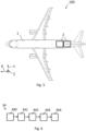
- Figs. 1 , 2 , 3 and 4 show a schematic illustration of an aircraft fuselage 1 for releasing a fuel tank 2 from inside the aircraft fuselage 1 in case of emergency according to an embodiment of the invention.
- the aircraft fuselage 1 comprises an outer structure 3, a mounting device 4, an openable release door 5, an enclosure 6 and a reversible quick release element 7.
- the outer structure 3 can include a frame and a stringer.
- the mounting device 4 or tank fitting, respectively, is configured to releasably secure a fuel tank 2 in an inside, in particular an inner tank compartment, of the outer structure 3.
- the tank fitting 4 comprises the enclosure 6 which encloses a shell surface of the fuel tank 2 at least sectionwise, here the lower and lateral section. Furthermore, the tank fitting 4 comprises three pads. The upper section of the fuel tank 2 is enclosed sectionwise by the three pads.
- the enclosure 6 comprises the reversible quick release element 7 which locks the enclosure 6 in a secured status and is driven electro mechanically, or hydraulically to open the enclosure 6. Therefore, the quick release element 7 can be operated semi-automatically.
- a hydrogen detection system (not shown) can be positioned at or coupled to the tank fitting 4 and/or the release door 5 that when a hydrogen leak is detected the hydrogen detection system may activate a signal for informing a pilot.
- the quick release element 7 and the release door 5 can be activated by the pilot. After activation by the pilot the fuel tank 2 is automatically released through the release door 5.
- the enclosure 6 comprises a plurality of chain links 8 and a plurality of locking pins 9.
- the plurality of chain links 8 are connected to each other by the locking pin 9.
- the reversible quick release element 7 is configured as a reversible quick release pin connecting two of the plurality of chain links 8.
- the quick release pin 7 is arranged at the lowest point of the tank fitting 4. In other words, the quick release pin 7 is arranged in the middle of the release door 5, for example.
- the openable release door 5 separates the inner tank compartment from an outside of the outer structure 3.
- the release door 5 consists of two door parts.
- the two door parts can be configured as a double door.
- the release door 5 is positioned in relation to the mounting device 4 such that the fuel tank is released through the release door 5 when the mounting device 4 releases the fuel tank 2.
- the two door parts form a quarter of the aircraft fuselage 1 each.
- the release door 5 extends over the lower half of the aircraft fuselage 1 with regard to a cross-section view.
- the openable release door 5 is positioned on a bottom side 3a of the outer structure 3, in Fig. 2 and 3 it corresponds to the lower side of the outer structure 3, such that the fuel tank 2 drops off the aircraft fuselage 1 by gravity.
- the openable release door 5 is hinged to the outer structure 3 and opened by a hydraulic pivot mechanism.
- the release door 5 is illustrated in a fully open status.
- a hinge axis of the hinged release door 5 is substantially corresponding to the longitudinal axis of the aircraft fuselage 1.
- the release door 5 is configured as a conventional landing gear door, wherein its size and functionality is scalable to any demand.
- the release door 5 is hinged at an upper section of the release door 5 such that the release door 5 opens sidewards.
- Fig. 2 the aircraft fuselage 1 is schematically illustrated with an opened release door 5 and a secured mounting device 4.
- the aircraft fuselage 1 of Fig. 2 differs from the aircraft fuselage 1 of Fig. 1 in that a section of the aircraft fuselage 1 is lined with a fire resistant lining 10 for retaining flames and a section of an inner side of the outer structure 3 comprises a flame deflector shielding 11.
- these section correspond to an inner side of the first 5 and second release door 9 as well as the walls that surround the fuel tank 2, for example the inner walls of the inner tank compartment.
- Fig. 3 shows the aircraft fuselage 1 according to Figs. 1 and 2 with an opened release door 5 and a released tank fitting 4.
- the openable release door 5 is configured reclosable, in particular reclosable during flight.
- an aerodynamic property of the aircraft fuselage 1 is not influenced by a protruding release door 5 and/or an uncovered opening as it is present in Figs. 2 and 3 .
- Fig. 4 the aircraft fuselage according to Figs. 1 , 2 and 3 is shown with a reclosed release door 5.
- Fig. 5 shows a schematic illustration of an aircraft 100 according to a further embodiment of the invention.
- the aircraft 100 is configured as a passenger or cargo aircraft.
- the aircraft 100 comprises an aircraft fuselage, in particular an aircraft fuselage 1 according to Fig. 1 , 2 , 3 or 4 , and two fuel tanks 2.
- Each fuel tank 2 is releasably secured by the mounting device 4 in an inside, in particular in an inner tank compartment, of the outer structure 3.
- the openable releasable door 5 is located on a bottom side of the aircraft fuselage 1.
- the aircraft 100 comprises two fuel tanks 2 but is not limited to that number.
- the aircraft 100 can also comprise one, three or more fuel tanks 2.
- the three or more fuel tanks are arranged behind each other and/or next to each other such that each fuel tank 2 can be released from the aircraft fuselage 1 individually.
- the two fuel tanks 2 are fluidly connected to a standard fueling and transfer line of the aircraft 100 when secured by the mounting device 4.
- the two fuel tanks supply an engine of the aircraft 100 with fuel.
- the fuel can be kerosene or hydrogen, for example. Therefore, the fuel tank may be configured as a cryogenic tank for storing hydrogen.
- the aircraft 100 comprises a second fuel tank which is independent from the two fuel tanks and integrated into a wing of the aircraft 100.
- the second fuel tank is configured for storing kerosene, for example.
- the two fuel tanks 2 can store hydrogen and the second fuel tank can store kerosene, for example.
- the two fuel tanks and the second fuel tank store the same fuel.
- Fig. 6 shows a flow chart for a method M for releasing a fuel tank from inside the aircraft fuselage in case of emergency according to a further embodiment of the invention.
- the fuel tank 2 is released from inside the aircraft fuselage 1 according to Fig. 1 , 2 , 3 or 4 .
- the method M comprises the steps of detecting M0, switching M1, opening M2, disconnecting M3 and closing M4.
- the method M could start with detecting M0 a leakage of the fuel tank 2.
- the leakage can be detected by a user or a hydrogen detection system positioned at or coupled to the fuel tank 2.
- a fuel supply from the fuel tank 2 is switched to a second fuel tank which is independent from the fuel tank 2.
- the second fuel tank is not to be released.
- the fuel supply does not need to be switched from the fuel tank 2 to the second fuel tank when the fuel tank 2 does not supply fuel at the moment of starting the method M.
- a release door 5 is opened.
- the release door 5 separates an inside from an outside of an outer structure 3 of the aircraft fuselage 1.
- the hydrogen detection system may activate the quick release element and the release door.
- the quick release element and/or the release door can be activated or controlled by an activation system or a control and steering unit, respectively.
- the fuel tank 2 is disconnected.
- the fuel tank 2 is releasably secured by a mounting device 4 in the inside of the outer structure 3 from the mounting device 4 such that the fuel tank 2 releases the aircraft fuselage 1 through the open release door 5.
- the fuel tank 2 drops off the aircraft fuselage 1 through the open release door 5 by a gravity force.
- the fuel tank 2 can separate downward away from the aircraft fuselage 1.
- the release door 5 is re-closed after the fuel tank 2 has released the aircraft fuselage 1.
- the release door 5 is closed during flight with a regular flight speed.
- the release door 5 can be closed in any desired altitude. Therefore, a drive mechanism of the release door 5 is designed to overcome the higher loads.
Landscapes
- Engineering & Computer Science (AREA)
- Aviation & Aerospace Engineering (AREA)
- Cooling, Air Intake And Gas Exhaust, And Fuel Tank Arrangements In Propulsion Units (AREA)
Priority Applications (2)
| Application Number | Priority Date | Filing Date | Title |
|---|---|---|---|
| EP23200509.0A EP4530197A1 (fr) | 2023-09-28 | 2023-09-28 | Fuselage d'aéronef et procédé de libération d'un réservoir de carburant de l'intérieur du fuselage d'aéronef en cas d'urgence ainsi qu'aéronef |
| CN202411269511.3A CN119705840A (zh) | 2023-09-28 | 2024-09-11 | 用于在紧急情况下从飞行器机身内部释放燃料罐的飞行器机身和方法以及飞行器 |
Applications Claiming Priority (1)
| Application Number | Priority Date | Filing Date | Title |
|---|---|---|---|
| EP23200509.0A EP4530197A1 (fr) | 2023-09-28 | 2023-09-28 | Fuselage d'aéronef et procédé de libération d'un réservoir de carburant de l'intérieur du fuselage d'aéronef en cas d'urgence ainsi qu'aéronef |
Publications (1)
| Publication Number | Publication Date |
|---|---|
| EP4530197A1 true EP4530197A1 (fr) | 2025-04-02 |
Family
ID=88236556
Family Applications (1)
| Application Number | Title | Priority Date | Filing Date |
|---|---|---|---|
| EP23200509.0A Pending EP4530197A1 (fr) | 2023-09-28 | 2023-09-28 | Fuselage d'aéronef et procédé de libération d'un réservoir de carburant de l'intérieur du fuselage d'aéronef en cas d'urgence ainsi qu'aéronef |
Country Status (2)
| Country | Link |
|---|---|
| EP (1) | EP4530197A1 (fr) |
| CN (1) | CN119705840A (fr) |
Citations (5)
| Publication number | Priority date | Publication date | Assignee | Title |
|---|---|---|---|---|
| GB127842A (en) * | 1917-05-26 | 1919-06-19 | Robert Elgin Lloyd Lott | Improvements relating to Means for Supporting Fuel Tanks on Aeroplanes and Air-ships. |
| FR500076A (fr) * | 1918-11-16 | 1920-03-02 | Frank Phelps | Perfectionnements apportés aux récipients à combustible |
| US4306693A (en) | 1977-05-04 | 1981-12-22 | Cooper Isaac B | Aircraft with jettisonable fuel tank means |
| RU2243925C2 (ru) * | 2003-02-26 | 2005-01-10 | Нигматуллин Нургазиз Фаттахович | Самолет с топливом, расфасованным в съемные баки |
| CN110450955A (zh) * | 2019-08-21 | 2019-11-15 | 深圳洲际通航投资控股有限公司 | 一种稳定续航大载重无人机优化结构 |
-
2023
- 2023-09-28 EP EP23200509.0A patent/EP4530197A1/fr active Pending
-
2024
- 2024-09-11 CN CN202411269511.3A patent/CN119705840A/zh active Pending
Patent Citations (5)
| Publication number | Priority date | Publication date | Assignee | Title |
|---|---|---|---|---|
| GB127842A (en) * | 1917-05-26 | 1919-06-19 | Robert Elgin Lloyd Lott | Improvements relating to Means for Supporting Fuel Tanks on Aeroplanes and Air-ships. |
| FR500076A (fr) * | 1918-11-16 | 1920-03-02 | Frank Phelps | Perfectionnements apportés aux récipients à combustible |
| US4306693A (en) | 1977-05-04 | 1981-12-22 | Cooper Isaac B | Aircraft with jettisonable fuel tank means |
| RU2243925C2 (ru) * | 2003-02-26 | 2005-01-10 | Нигматуллин Нургазиз Фаттахович | Самолет с топливом, расфасованным в съемные баки |
| CN110450955A (zh) * | 2019-08-21 | 2019-11-15 | 深圳洲际通航投资控股有限公司 | 一种稳定续航大载重无人机优化结构 |
Also Published As
| Publication number | Publication date |
|---|---|
| CN119705840A (zh) | 2025-03-28 |
Similar Documents
| Publication | Publication Date | Title |
|---|---|---|
| US5356097A (en) | Segmented safety aircraft | |
| EP4296158A1 (fr) | Carénage variable pour une installation de système de conduit d'hydrogène et ses utilisations | |
| US9327149B2 (en) | Aerial fire suppression system | |
| EP3856641B1 (fr) | Module de manipulation de carburant destiné à un aéronef | |
| US10807706B2 (en) | Jettisonable emergency exit for a vehicle | |
| EP3770062B1 (fr) | Aéronef avec un système de porte électromécanique | |
| EP3378757B1 (fr) | Avion ayantune région de sous-plancher logeant un compartiment auxiliaire | |
| CN100515862C (zh) | 飞机起落架的操纵系统以及包含该系统的飞机 | |
| US10486790B2 (en) | Maintenance step for a helicopter | |
| US10829231B2 (en) | Integral life raft, survival kit, and step | |
| CN109455302A (zh) | 一种适用于中大型无人机的应急回收伞系统 | |
| EP4530197A1 (fr) | Fuselage d'aéronef et procédé de libération d'un réservoir de carburant de l'intérieur du fuselage d'aéronef en cas d'urgence ainsi qu'aéronef | |
| US11603180B2 (en) | Vehicle with at least one emergency exit system | |
| US20250108908A1 (en) | Aircraft tank device for increasing a flight range and a wing area of an aircraft as well as aircraft | |
| CA3194542A1 (fr) | Giravion comportant une unite de stockage d'une source d'energie | |
| US12576984B2 (en) | Fuselage for an aircraft or spacecraft, and aircraft or spacecraft | |
| CN106628196B (zh) | 一种带组合式后盖的飞机阻力伞舱 | |
| CN105270600B (zh) | 形成通道门并且包括增压空气的排放控制阀的机身设备 | |
| US12570408B2 (en) | Aircraft fuselage and method for releasing a fuel tank from inside the aircraft fuselage in case of emergency as well as aircraft | |
| CN105836145A (zh) | 具有悬装于机身承重中间层下方的燃油箱的旋翼飞行器 | |
| CN209506102U (zh) | 一种适用于中大型无人机的应急回收伞系统 | |
| US20230009616A1 (en) | Retractable cargo hook | |
| EP2293982B1 (fr) | Système de largage de carburant | |
| EP4635851A1 (fr) | Assemblage d'aéronef et aéronef | |
| US20250026475A1 (en) | An external cargo adapter for use with a rotorcraft |
Legal Events
| Date | Code | Title | Description |
|---|---|---|---|
| PUAI | Public reference made under article 153(3) epc to a published international application that has entered the european phase |
Free format text: ORIGINAL CODE: 0009012 |
|
| STAA | Information on the status of an ep patent application or granted ep patent |
Free format text: STATUS: THE APPLICATION HAS BEEN PUBLISHED |
|
| AK | Designated contracting states |
Kind code of ref document: A1 Designated state(s): AL AT BE BG CH CY CZ DE DK EE ES FI FR GB GR HR HU IE IS IT LI LT LU LV MC ME MK MT NL NO PL PT RO RS SE SI SK SM TR |
|
| STAA | Information on the status of an ep patent application or granted ep patent |
Free format text: STATUS: REQUEST FOR EXAMINATION WAS MADE |
|
| 17P | Request for examination filed |
Effective date: 20250922 |