EP4530207A1 - Dispositif pour maintenir l'ouverture d'un sac - Google Patents
Dispositif pour maintenir l'ouverture d'un sac Download PDFInfo
- Publication number
- EP4530207A1 EP4530207A1 EP24194293.7A EP24194293A EP4530207A1 EP 4530207 A1 EP4530207 A1 EP 4530207A1 EP 24194293 A EP24194293 A EP 24194293A EP 4530207 A1 EP4530207 A1 EP 4530207A1
- Authority
- EP
- European Patent Office
- Prior art keywords
- bag
- opening
- holding
- holding elements
- coffee powder
- Prior art date
- Legal status (The legal status is an assumption and is not a legal conclusion. Google has not performed a legal analysis and makes no representation as to the accuracy of the status listed.)
- Pending
Links
Images



Classifications
-
- B—PERFORMING OPERATIONS; TRANSPORTING
- B65—CONVEYING; PACKING; STORING; HANDLING THIN OR FILAMENTARY MATERIAL
- B65B—MACHINES, APPARATUS OR DEVICES FOR, OR METHODS OF, PACKAGING ARTICLES OR MATERIALS; UNPACKING
- B65B1/00—Packaging fluent solid material, e.g. powders, granular or loose fibrous material, loose masses of small articles, in individual containers or receptacles, e.g. bags, sacks, boxes, cartons, cans, or jars
- B65B1/02—Machines characterised by the incorporation of means for making the containers or receptacles
-
- B—PERFORMING OPERATIONS; TRANSPORTING
- B65—CONVEYING; PACKING; STORING; HANDLING THIN OR FILAMENTARY MATERIAL
- B65B—MACHINES, APPARATUS OR DEVICES FOR, OR METHODS OF, PACKAGING ARTICLES OR MATERIALS; UNPACKING
- B65B1/00—Packaging fluent solid material, e.g. powders, granular or loose fibrous material, loose masses of small articles, in individual containers or receptacles, e.g. bags, sacks, boxes, cartons, cans, or jars
- B65B1/20—Reducing volume of filled material
- B65B1/24—Reducing volume of filled material by mechanical compression
-
- B—PERFORMING OPERATIONS; TRANSPORTING
- B65—CONVEYING; PACKING; STORING; HANDLING THIN OR FILAMENTARY MATERIAL
- B65B—MACHINES, APPARATUS OR DEVICES FOR, OR METHODS OF, PACKAGING ARTICLES OR MATERIALS; UNPACKING
- B65B43/00—Forming, feeding, opening or setting-up containers or receptacles in association with packaging
- B65B43/26—Opening or distending bags; Opening, erecting, or setting-up boxes, cartons, or carton blanks
- B65B43/34—Opening or distending bags; Opening, erecting, or setting-up boxes, cartons, or carton blanks by internal pressure
-
- B—PERFORMING OPERATIONS; TRANSPORTING
- B65—CONVEYING; PACKING; STORING; HANDLING THIN OR FILAMENTARY MATERIAL
- B65B—MACHINES, APPARATUS OR DEVICES FOR, OR METHODS OF, PACKAGING ARTICLES OR MATERIALS; UNPACKING
- B65B43/00—Forming, feeding, opening or setting-up containers or receptacles in association with packaging
- B65B43/42—Feeding or positioning bags, boxes, or cartons in the distended, opened, or set-up state; Feeding preformed rigid containers, e.g. tins, capsules, glass tubes, glasses, to the packaging position; Locating containers or receptacles at the filling position; Supporting containers or receptacles during the filling operation
- B65B43/46—Feeding or positioning bags, boxes, or cartons in the distended, opened, or set-up state; Feeding preformed rigid containers, e.g. tins, capsules, glass tubes, glasses, to the packaging position; Locating containers or receptacles at the filling position; Supporting containers or receptacles during the filling operation using grippers
- B65B43/465—Feeding or positioning bags, boxes, or cartons in the distended, opened, or set-up state; Feeding preformed rigid containers, e.g. tins, capsules, glass tubes, glasses, to the packaging position; Locating containers or receptacles at the filling position; Supporting containers or receptacles during the filling operation using grippers for bags
-
- B—PERFORMING OPERATIONS; TRANSPORTING
- B65—CONVEYING; PACKING; STORING; HANDLING THIN OR FILAMENTARY MATERIAL
- B65B—MACHINES, APPARATUS OR DEVICES FOR, OR METHODS OF, PACKAGING ARTICLES OR MATERIALS; UNPACKING
- B65B29/00—Packaging of materials presenting special problems
Definitions
- the invention relates to a device for holding open the opening of a bag.
- the device is particularly suitable for holding open bags in filling machines for filling coffee powder.
- Coffee powder is usually filled into bags from above by gravity, with a defined, weighed amount of coffee powder falling into the bag. Additionally, compacting the coffee powder is often useful when filling coffee powder, particularly to remove air from the bag and to ensure the coffee powder is stored in the bag with as little air as possible. Compacting is usually done with a plunger, which compresses the coffee powder already in the bag by pressing down on the coffee powder from above.
- the invention relates to a device for holding open the opening of a bag, in particular in a filling machine for filling coffee powder, the bag having a polygonal bag base surface from which a circumferential bag wall extends upwards and surrounds the opening opposite the bag base surface, the device having holding elements which can be moved from starting positions into a central region within an opening surface of the opening from above into the opening, in order to then be moved apart within the opening into deflected positions in order to open up the bag wall at corners, a direction of movement of the holding elements from the starting positions to the deflected positions being aligned at an angle of approach to both wall surface sections of the bag wall which meet in a corner of the bag.
- the described device is preferably used in a filling machine for filling coffee powder between a filling station for filling the coffee powder into the bag and a compacting station for compacting/compressing the coffee powder in the bag.
- a compacting station normally has a stamp that moves into the opening of the bag from above and with which pressure is exerted on the coffee powder contained in the bag. It is desirable to shape a stamp so that it is adapted as precisely as possible to the shape of the opening or bag, so that pressure can be exerted as evenly as possible on the surface of the coffee powder in the bag with the stamp.
- the bag wall extends upwards from a bag base, which forms the bottom of the bag.
- the bag wall is perpendicular to the base throughout.
- An opening surface of the opening preferably corresponds to the bag base and lies in a plane parallel to the bag base above the bag wall.
- An upper edge or an upper end face of the The bag wall encloses the opening or opening surface.
- deformations e.g., corrugations
- deviations between the opening surface and the base surface can occur. These deviations can vary depending on the situation and compromise process reliability. If the punch shape is precisely adapted to the shape of the opening, collisions can occur between the punch and the upper end face of the bag wall.
- the use of the device can also be advantageous for filling products into bags because the bag is held in a certain position with the device.
- the bag base is square, and the device has four retaining elements for the four corners.
- the bag base is rectangular with a longer and a shorter side.
- the bag base can also be square. In variant designs, however, the bag base can also have a different number of corners, e.g., three corners, five corners, or eight corners.
- the device then has a corresponding number of retaining elements.
- the bag is made of a monomaterial.
- a monomaterial is, in particular, a material that has a single-layer structure. The properties of the material are therefore essentially uniform across the thickness of the material. Monomaterials are particularly to be distinguished from materials that have a supporting layer and an additional have a barrier layer applied that prevents, for example, the diffusion of moisture into the bag.
- Monomaterials offer significant advantages over multi-layer materials in terms of their recycling capabilities because they do not represent mixtures of materials and therefore, in principle, no separation is required to ensure particularly good recycling.
- the monomaterial of the bag is a material based on polyethylene, which has good barrier properties.
- the bag is made from a flat starting material which is formed into a tube with a longitudinal seam.
- the bag has additional bottom seams in the area of the bag base or bottom, with which the bag is tightly closed at the bag base.
- the longitudinal seam (and preferably any other seam of the bag) is preferably created using joining methods, with thermal joining methods such as welding being used in particular.
- Heat is introduced into the bag material, which regularly creates internal stresses in the bag material.
- Such internal stresses promote the occurrence of corrugations.
- the formation of such a corrugation is also referred to as a "figure 8.”
- Such a corrugation forms particularly inwardly with monomaterials as the bag material and can therefore pose a particularly high risk of collision with a stamp for compacting/compressing the coffee powder in the bag.
- the use of the described device is particularly advantageous for a bag made of such a material.
- a corrugation created by a longitudinal seam The waviness caused by the wrinkles and their effect on the shape of the opening/opening area of the bag can be particularly effectively prevented. In particular, sections of the bag wall between the corners
- the holding elements are hook-shaped and have a holding section and a web section which are arranged at a hook angle to one another, wherein the holding sections in the deflected position rest against an inner surface of the bag wall in the corners and a holding length of the web sections specifies the deflected position of the holding sections.
- the holding section holds the bag in the deflected position.
- the holding section penetrates the bag opening to a depth corresponding to the penetration depth and rests against an inner surface of the bag wall at its corners for a length corresponding to the penetration depth.
- the holding elements are each rotatable about a rotational axis.
- the movement of the holding elements from the starting position to the deflected position is preferably a rotational movement about the rotational axis. This ensures, in particular, that the holding elements are moved from above into the central region of the opening and then subsequently outwards into the deflected position.
- the holding sections In the deflected position, the holding sections preferably run parallel to the bag wall and span the bag wall starting from its inner surface. Previously (in the starting position), the holding sections are inclined relative to the bag wall.
- the web length is the length of the holding section spaced from the rotation axis by the web section.
- the web length is the distance from the rotation axis to the deflected position projected onto a plane of the bag opening. It is also advantageous if the holding elements are designed with a transition curve between the web sections and the holding sections.
- the movement of the holding elements from the starting position to the deflected position can also be multi-part, for example with an initial (linear) movement downwards into the central area within the opening surface followed by a separate, further (linear) movement outwards.
- Combinations of linear movements and rotary movements for moving the holding elements from starting positions to deflected positions are also possible.
- the movements into the opening and the movement outwards can overlap in time and space. It is not necessary for these movements to occur completely one after the other. What is important is that the holding elements approach the inner surface of the bag wall. Therefore, a movement component of the movement into the opening preferably precedes at least partially in time a movement component of the movement outwards.
- the holding elements have a rounded cross-section at least in the area of holding sections that are in contact with the bag wall.
- the holding elements are made of a rod element which at least partially forms the holding section and the web section and which is optionally bent to form the described transition curve.
- holding elements are designed as round bars which form holding sections and web sections, wherein the holding section and web section merge into one another with a transition base.
- the rounded cross-section of the holding sections is particularly advantageous in ensuring particularly gentle contact between the holding section and the bag wall.
- the rounded cross-section prevents damage to the bag because there are no sharp edges that could cut into the material of the bag wall.
- the holding elements are each rotatably mounted on axes of rotation above a bag arranged in the device in order to be movable from the starting positions into the deflected positions with a tilting movement about the respective axis of rotation.
- holding elements are arranged in particular above the opening of the bag.
- the holding elements When the holding elements enter the opening area, the holding elements preferably enter the opening (only) through a central area located within the opening area.
- the central area and the starting positions above the opening are set up in such a way that the holding elements always have a safety distance from the bag wall when entering the opening. This ensures that when the holding elements move in a direction from the starting positions to the deflected positions, the holding elements always move towards an inner surface of the bag wall and are thus set up to clamp the bag wall starting from the inner surface at the corners when they have been moved into the deflected position.
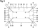
- a direction of movement of the holding elements from the starting positions to the deflected positions is aligned at an approach angle to both wall surface sections of the bag wall that meet in a corner of the bag.
- the angle of the movement direction to each surface section of the bag wall is at least 25 degrees.
- the approach angle is the angle between a direction of movement of the retaining elements and wall sections of the stretched bag wall when the retaining elements have each been moved into the deflected positions.
- the angle between two wall surface sections of the bag that meet at the corner is preferably 90°.
- the angle of the direction of movement is then particularly preferably 45 degrees (with a tolerance of 5 degrees or less).
- the device preferably has at least one drive for moving the holding elements from the starting positions into the deflected positions, wherein the drive is designed to limit a force exerted on the bag wall by the holding elements when approaching the deflected positions.
- a limitation of the applied force can be achieved, for example, by a spring element in the drive.
- a rod gear for transmitting a drive force from the drive to the holding elements can, for example, have a spring section that limits the force exerted by the drive on the holding element.
- a filling machine for filling coffee powder into bags comprising at least one filling station for filling coffee powder through the opening of the bag and further comprising at least one compacting station for compacting coffee powder in the bag with a stamp which is used to compact the coffee powder in the bag from above can be moved into the opening of the bag, wherein a described device for holding the opening of the bag is arranged in front of the compacting station in order to hold the opening for carrying out the compaction.
- the stamp for compacting the coffee powder with the compacting station has recesses for the holding elements of the device in their deflected position.
- the filling machine has a forming device for forming bags from a flat starting material, wherein the forming device is designed to form a tube from the flat starting material with a longitudinal seam in order to subsequently form bags from the tube.
- the stamp can achieve particularly good coverage of the surface of the coffee powder in the bag and particularly good compaction/compression/compacting of the coffee powder can be achieved.
- the process is particularly advantageous if the bag is made of a monomaterial.
- the process is particularly advantageous if the bag is made from a flat starting material which is formed into a tube with a longitudinal seam.
- the Fig. 1 shows a described device 1 with holding elements 8 in the starting position 9.
- Fig. 2 shows the device 1 from Fig. 1 with holding elements 8 in the deflected position 12.
- a bag 3 can be seen with the opening 2 on its upper side.
- the bag 3 has a bag wall 7 which extends upwards from a bag base 6 and encloses the opening 2 of the bag 3.
- the bag base 6 corresponds to a bottom of the bag 3.
- the bag wall 7 extends essentially vertically upwards from the bag base 6 or from the bottom of the bag 3. Accordingly, the opening 2 also essentially has the shape of the bag base 6.
- the bag wall 7 can have a corrugation 33 in some areas, as a result of which the shape of the opening 2 can deviate from the shape of the bag base 6.
- the corrugation 33 can occur as a result of a longitudinal seam (not shown separately here), in particular when the bag 3 is made of a monomaterial. In principle, however, such a corrugation 33 can also occur for other reasons.
- the holding elements 8 are provided with at least one Fig. 1 and 2 schematically illustrated drive 25 around rotation axes 21 in order to move from the starting position 9 according to Fig. 1 into the deflected position 12 according to Fig. 2 According to the Fig. 1 and 2
- the drive 25 drives the holding elements 8 via rod gears 34. This is a possible design variant.
- the holding elements 8 are located above the opening 2 of the bag 3. In fact, there is even a distance between the opening surface of the opening 2 and the central area or the holding elements 8, which is set so that in the event of any possible deformation of the bag 3 or the bag wall 7, the holding elements 8 are still located within the opening surface and, when moving into the deflected position 12, are in any case moved from the inside to the bag wall 7. Because the holding elements 8 are in the starting position 9 above the opening 2 of the bag 3, the bag 3 can be moved from the side under the holding elements 8.
- the holding elements 8 When the holding elements 8 move into the deflected position 12, the holding elements 8 are moved downwards and outwards (towards the bag wall 7) into the corners of the bag wall 7. During the movement, the holding elements 8 enter the opening surface 11 of the opening 2 through a central area and always have a safety distance from the bag wall 7. After or parallel to the entry of the holding elements 8 into the opening 2 through the central area, the holding elements 8 are moved outwards and into the deflected positions 12. This opens up the bag 3 or the opening 2 of the bag 3.
- the corrugation 33 is smoothed out.
- the device 1 preferably has four holding elements 8 with which the opening 2 of a rectangular bag 3 with four corners 13 can be clamped.
- the rotation axes 21 of the individual holding elements 8 are in the Fig. 1 and 2 partially obscured and therefore not all equally recognizable.
- a single holding element 8 is used to explain the structure in Fig. 3 in a deflected position 12. It can be seen that the holding element 8 is movable about a rotation axis 21 by means of a drive 25.
- the holding element 8 consists of a round rod with a round cross-section 31.
- the holding element 8 has a holding section 15 which rests against the bag wall 7 when the holding element 8 (as in Fig. 2 shown) is brought into the deflected position 12.
- a holding element 8 designed as a round rod has the advantage that it has no edges that could damage the bag wall 7.
- the holding section 15 merges into a web section 16 of the holding element 8 in a transition curve 20.
- the web section 16 and the holding section 15 for holding the bag 3 form a hook with a hook angle 17, which is preferably 90 degrees.
- a web length 19 of the web section 16 or a web length 19 from the axis of rotation 21 to the holding section 15 defines a precise location of the holding section 15 in the deflected position 12.
- the web length 19 ensures that the holding element 8, when moving from the starting position to the deflected position 12, is moved not only outwards but also downwards, into the opening 2 of the bag 3.
- the holding element 8 When the holding element 8 is in the deflected position 12, it has penetrated into the opening 2 or the bag 3 with a penetration depth 26 and rests against the inner surface 18 of the bag wall 7 with a length corresponding to the penetration depth 26.
- the penetration depth 26 is configured such that the holding element 8 sufficiently holds the bag wall 7 and, in particular, the holding element 8 cannot slip off the bag wall, but rather the opening 2 is securely clamped by the holding elements 8.
- the penetration depth 26 is, for example, more than 5 mm [millimeters] and particularly preferably more than 10 mm.
- the Fig. 4 a schematic representation of a described filling machine 4 with a described device 1.
- the steps of the method also described here for filling coffee powder 5 into a bag 3 are assigned to individual stations of the filling machine 4.
- step a) at least one bag 3 is provided.
- This may, for example, also include the production of the bag 3 from a flat starting material by forming a tube from the starting material with a longitudinal seam. Furthermore, this may include the separation of the material for a bag 3 from the starting material, as well as the formation of a base by folds and/or further seams.
- step a) also includes the erection of the bag for subsequent filling with coffee powder 5 in a filling station 27 (step b)).
- the filling machine 4 has a described device 1 with holding elements 8, with which the opening 2 of the bag 3 can be held open. This corresponds to step c) of the described method.
- the device 1 is preferably arranged in the filling process direction downstream of a filling station 27 for filling the coffee powder 5 into the bag and upstream of a compacting station 28 for compacting the coffee powder 5.
- the device 1 can also be arranged upstream of the filling station 27 and hold the bag 3 or its opening 2 for filling.
Landscapes
- Engineering & Computer Science (AREA)
- Mechanical Engineering (AREA)
- Supplying Of Containers To The Packaging Station (AREA)
- Packages (AREA)
Applications Claiming Priority (1)
| Application Number | Priority Date | Filing Date | Title |
|---|---|---|---|
| DE102023122623.1A DE102023122623A1 (de) | 2023-08-23 | 2023-08-23 | Vorrichtung zum Aufhalten der Öffnung eines Beutels |
Publications (1)
| Publication Number | Publication Date |
|---|---|
| EP4530207A1 true EP4530207A1 (fr) | 2025-04-02 |
Family
ID=92409134
Family Applications (1)
| Application Number | Title | Priority Date | Filing Date |
|---|---|---|---|
| EP24194293.7A Pending EP4530207A1 (fr) | 2023-08-23 | 2024-08-13 | Dispositif pour maintenir l'ouverture d'un sac |
Country Status (2)
| Country | Link |
|---|---|
| EP (1) | EP4530207A1 (fr) |
| DE (1) | DE102023122623A1 (fr) |
Citations (4)
| Publication number | Priority date | Publication date | Assignee | Title |
|---|---|---|---|---|
| US3748819A (en) * | 1970-11-23 | 1973-07-31 | Christenssons Maskiner | Arrangement for filling and closing packages, comprising an outer package and an inner package loosely applied therein |
| US3903677A (en) * | 1974-06-28 | 1975-09-09 | Us Agriculture | Opening and gripping mechanism for automatic produce-bagging machine that uses factory-roll polyethylene net tubing |
| US20060196152A1 (en) * | 2005-03-04 | 2006-09-07 | Hans-Peter Wild | Device and method for filling foil bags with food |
| US20120144779A1 (en) * | 2010-12-08 | 2012-06-14 | Sealed Air (New Zealand) | Apparatus and Method for Shaping and Holding a Bag in an Open Condition |
Family Cites Families (7)
| Publication number | Priority date | Publication date | Assignee | Title |
|---|---|---|---|---|
| DE232162C (fr) * | ||||
| CH574806A5 (fr) * | 1974-02-13 | 1976-04-30 | Sig Schweiz Industrieges | |
| JPH01111622A (ja) * | 1987-10-14 | 1989-04-28 | Toyama Sanki Kk | 袋状物開口装置 |
| DE19505300C2 (de) * | 1995-02-16 | 1998-02-19 | Ips Int Packaging Syst | Standfeste Tüte |
| US10836525B1 (en) * | 2017-03-07 | 2020-11-17 | Amazon Technologies, Inc. | Robotic gripper for bagging items |
| CN109229580A (zh) * | 2018-10-12 | 2019-01-18 | 安徽永成电子机械技术有限公司 | 一种物料袋撑袋机构 |
| US12291367B2 (en) * | 2021-12-13 | 2025-05-06 | Wacker Chemie Ag | Method and system for automatically packaging comminuted silicon |
-
2023
- 2023-08-23 DE DE102023122623.1A patent/DE102023122623A1/de active Pending
-
2024
- 2024-08-13 EP EP24194293.7A patent/EP4530207A1/fr active Pending
Patent Citations (4)
| Publication number | Priority date | Publication date | Assignee | Title |
|---|---|---|---|---|
| US3748819A (en) * | 1970-11-23 | 1973-07-31 | Christenssons Maskiner | Arrangement for filling and closing packages, comprising an outer package and an inner package loosely applied therein |
| US3903677A (en) * | 1974-06-28 | 1975-09-09 | Us Agriculture | Opening and gripping mechanism for automatic produce-bagging machine that uses factory-roll polyethylene net tubing |
| US20060196152A1 (en) * | 2005-03-04 | 2006-09-07 | Hans-Peter Wild | Device and method for filling foil bags with food |
| US20120144779A1 (en) * | 2010-12-08 | 2012-06-14 | Sealed Air (New Zealand) | Apparatus and Method for Shaping and Holding a Bag in an Open Condition |
Also Published As
| Publication number | Publication date |
|---|---|
| DE102023122623A1 (de) | 2025-02-27 |
Similar Documents
| Publication | Publication Date | Title |
|---|---|---|
| EP0145832B1 (fr) | Procédé et appareil pour la fabrication d'un objet revêtu | |
| EP1269608B1 (fr) | Appareil de production de paquets formes d'elements en tole | |
| WO2017174347A1 (fr) | Dispositif et procédé pour façonner des emballages fermés | |
| EP3401227A1 (fr) | Procédé de déformation tridimensionnelle de matériau plat | |
| EP0162119B1 (fr) | Dispositif pour la fabrication d'un emballage à partir d'un flan plat | |
| DE69104183T2 (de) | Wirbelbettvorrichtung und Verfahren zu ihrer Herstellung. | |
| DE60005453T2 (de) | Beutel mit durch einen schieber betätigten verschlussprofilen und verfahren zu seiner herstellung | |
| CH659962A5 (de) | Maschine zum herstellen eines abstandhaltenden innenrahmens fuer eine isolierglasscheibe. | |
| DE1142574B (de) | Vorrichtung zum Herstellen von Verpackungsbehaeltern | |
| DE3226879C2 (fr) | ||
| DE69101039T2 (de) | Vorrichtung zum Siegeln der offenen Enden von bereits mit Flüssigkeit oder pastösen Lösungen gefüllten Einzeldosenbehältern. | |
| EP1117497B1 (fr) | Dispositif d'aboutage, procede d'aboutage par enchevetrement et assemblage realise par aboutage par enchevetrement | |
| DE2942883C2 (de) | Vorrichtung zum Verschließen des Bodens einer rechteckigen aufgerichteten Faltschachtel | |
| EP1097802A2 (fr) | Procédé et appareil pour fermer une boíte pliante | |
| EP4530207A1 (fr) | Dispositif pour maintenir l'ouverture d'un sac | |
| DE102022117737A1 (de) | Verfahren zur Herstellung mindestens eines Verpackungselements | |
| DE2852022A1 (de) | Fuellstation fuer seitenfaltensaecke | |
| WO2001095413A1 (fr) | Separateur en forme de manche et son dispositif de production | |
| CH673604A5 (fr) | ||
| DE2654000B2 (de) | Maschine zum Ausbrechen von Nutzen | |
| DE4339962A1 (de) | Vorrichtung und Verfahren zur Herstellung von Sickenblechen mit planparallelen Außenkantenflächen | |
| EP3831726B1 (fr) | Machine d'emballage et procédé à fonction de repliage | |
| EP3912918A1 (fr) | Dispositif d'emballage pour petites marchandises et procédé de fabrication d'un tube blister comprenant plusieurs sacs blister | |
| EP0630809B1 (fr) | Dispositif de remplissage d'emballages, notamment de sacs en papier | |
| DE3238553C2 (de) | Verfahren zum Herstellen eines Behälters für Schüttgut aus einem flachgelegten Kunststoffschlauch und Vorrichtung zur Durchführung des Verfahrens |
Legal Events
| Date | Code | Title | Description |
|---|---|---|---|
| PUAI | Public reference made under article 153(3) epc to a published international application that has entered the european phase |
Free format text: ORIGINAL CODE: 0009012 |
|
| STAA | Information on the status of an ep patent application or granted ep patent |
Free format text: STATUS: THE APPLICATION HAS BEEN PUBLISHED |
|
| AK | Designated contracting states |
Kind code of ref document: A1 Designated state(s): AL AT BE BG CH CY CZ DE DK EE ES FI FR GB GR HR HU IE IS IT LI LT LU LV MC ME MK MT NL NO PL PT RO RS SE SI SK SM TR |
|
| STAA | Information on the status of an ep patent application or granted ep patent |
Free format text: STATUS: REQUEST FOR EXAMINATION WAS MADE |
|
| 17P | Request for examination filed |
Effective date: 20250924 |
|
| RAP3 | Party data changed (applicant data changed or rights of an application transferred) |
Owner name: SYNTEGON TECHNOLOGY GMBH |