EP4530403A1 - Kopplungselement, barriereelement und barriere - Google Patents
Kopplungselement, barriereelement und barriere Download PDFInfo
- Publication number
- EP4530403A1 EP4530403A1 EP23200834.2A EP23200834A EP4530403A1 EP 4530403 A1 EP4530403 A1 EP 4530403A1 EP 23200834 A EP23200834 A EP 23200834A EP 4530403 A1 EP4530403 A1 EP 4530403A1
- Authority
- EP
- European Patent Office
- Prior art keywords
- barrier
- coupling element
- coupling
- protrusion
- along
- Prior art date
- Legal status (The legal status is an assumption and is not a legal conclusion. Google has not performed a legal analysis and makes no representation as to the accuracy of the status listed.)
- Pending
Links
Images


Classifications
-
- E—FIXED CONSTRUCTIONS
- E01—CONSTRUCTION OF ROADS, RAILWAYS, OR BRIDGES
- E01F—ADDITIONAL WORK, SUCH AS EQUIPPING ROADS OR THE CONSTRUCTION OF PLATFORMS, HELICOPTER LANDING STAGES, SIGNS, SNOW FENCES, OR THE LIKE
- E01F15/00—Safety arrangements for slowing, redirecting or stopping errant vehicles, e.g. guard posts or bollards; Arrangements for reducing damage to roadside structures due to vehicular impact
- E01F15/02—Continuous barriers extending along roads or between traffic lanes
- E01F15/08—Continuous barriers extending along roads or between traffic lanes essentially made of walls or wall-like elements ; Cable-linked blocks
- E01F15/088—Details of element connection
Definitions
- the invention relates to a coupling element configured to form part of a first barrier element and to form part of a connection between the first barrier element and a second barrier element.
- the invention also relates to a barrier element comprising a first and a second coupling element being arranged at a respective end of the barrier element.
- the invention also relates to a barrier comprising a plurality of barrier elements.
- barrier In order to improve road safety, it is common practice to separate different traffic areas from each other by some kind of barrier or separator. Different traffic areas may e.g., be on one side one more lanes of traffic travelling in a first direction and on the other side one or more lanes of traffic travelling in a second, opposite, direction. Barriers may of course be used for various other reasons, such as protecting road vehicles from hazards just outside the road, protecting surrounding environment from the hazard of vehicles leaving the intended lane, providing a safety separation between neighboring lanes, etc.
- the barrier may be in the form of metal rails, wire rails, or concrete barriers. Concrete barriers are typically formed of elongated barrier elements which are positioned one after the other. The barrier elements of concrete are heavy, and they are typically also interconnected to each other, whereby they form a strong barrier capable of sustaining heavy impacts from vehicles being heavy and/or traveling at high speed.
- Each barrier element is provided with a respective connecting element at each end face of the barrier element.
- Each connecting element comprises one leg having hook portions on both transverse sides thereof and one leg having an inwardly facing hook portion. The leg having two hook portions will interact with one hook with a corresponding leg of another connecting element and one hook with the single hook leg of the other connecting element.
- the designer should preferably take into account several design criteria, such as that the connecting element should be strong, it should be easy to produce, it should be easy to interconnect with similar connecting elements of neighboring barrier elements, and that there should be provided a strong connection between the connecting elements at the opposing ends of the respective barrier element.
- a coupling element configured to form part of a first barrier element and to form part of a connection between the first barrier element and a second barrier element, the coupling element being configured to extend along a longitudinal direction from the first barrier element to a free end of the coupling element, the coupling element comprising as seen along the longitudinal direction :
- the two inclined abutment surfaces are capable of transferring high loads between interconnected coupling elements. Moreover, the two inclined abutment surfaces will transfer load both by the inclined surfaces of the respective coupling element blocking each other's paths and by frictionally engaging each other whereby there will be a smooth load build-up. Moreover, the concept of having inclined abutment surfaces also makes the design comparably insensitive to deviations in shape. This makes it possible to have comparably wide tolerances, which in turn facilitates and reduces costs associated with manufacture.
- the comparable insensitivity to deviations also makes the system robust in the sense that it is capable of providing the intended function although the barriers are misaligned due to misplacement and/or due to the fact that they accommodate a curve or the like in the road where they are positioned.
- the comparably insensitivity also makes the system robust in the sense that it is capable of withstanding high loads also when being deformed by e.g., a vehicle having crashed into the barriers.
- the coupling element should be able to withstand transversely directed forces but that typically the dimensioning force will be a longitudinally acting force since any impact onto the barrier will tend to lead to a slightly transversal displacement of the barrier which in turn will basically be transformed into a tendency of a longitudinal separation of neighboring barrier elements.
- longitudinal refers to the direction along which the barrier element extends between the coupling elements at each end of the barrier element.
- the longitudinal direction typically extends along the ground.
- the transversal direction is transverse to the longitudinal direction and typically extends along the ground. From above refers to a direction directed downwardly along the normal to the ground. If the barrier element is positioned on a flat horizontal surface, the longitudinal and the transverse directions will typically be horizontal and the direction from above will typically be downwardly along vertical. In the description below, reference to directions will for clarity reason typically be referred to as if the barrier element is positioned on a flat horizontal surface.
- the inner side of the first protrusion refers in this context to the side facing the recess of said coupling element.
- the inner side of the first protrusion of a first coupling element will in installed state face an inner side of a first protrusion of a coupling element of another barrier element.
- Outer side is the other side of the first protrusion compared to the inner side.
- the outer side of the second portion of the first protrusion of a first coupling element will in installed state face a second protrusion of a coupling element of another barrier element.
- the coupling elements of the two neighboring barrier elements are configured to be coupled together by one of the barrier elements, such as the second barrier element, being moved vertically relative to the other barrier element.
- the barrier elements are moved into the intended position one after the other by a crane or the like.
- the barrier elements are lifted up from a trailer or the like and are lowered into position such that the coupling element of the second barrier element becomes coupled with the coupling element of the first barrier element.
- the cross-section disclosed is as seen from above, i.e., typically downwardly along vertical.
- the coupling elements have essentially uniform cross-section along vertical. In the preferred embodiment, they have uniform cross-section along vertical.
- the first barrier may have a coupling element being provided with a bottom portion forming a floor or the like below the portion interacting with the coupling element of the second barrier.
- the second barrier element may have a coupling element being provided with a top portion forming a lid or the like above the portion interacting with the coupling element of the first barrier.
- any such additional parts or portions will typically make the barrier elements asymmetric such that they have one coupling element of each kind in respective end which makes it necessary to always interconnect this specific combination of coupling elements with each other, which in turn means that every barrier element can only be oriented in one correct direction.
- the coupling elements and respective barrier element are symmetrical and preferably also identical in the sense that a second barrier element can be coupled to a first barrier element irrespective of which ends of the first barrier element and second barrier element are combined with each other. It may in this context be noted that the different features, portions, parts, details, etc. of the coupling element disclosed above and, in the following, typically refers to the design of the cross-section as seen from above.
- first and second inclined abutment surfaces are as seen in the cross-sectional view formed of a straight line.
- the first and second inclined abutment surfaces will form planar surfaces.
- the planar surfaces extends along vertical.
- the second protrusion may have on a side forming part of the recess a hook portion with an abutment surface which faces in a direction which has a component along the transverse direction being directed away from the first protrusion and a component along the longitudinal direction being directed towards the attachment portion.
- the first protrusion has on an outer side of the second portion a hook portion with an abutment surface which faces in a direction which has a component along the transverse direction being directed towards the second protrusion and a component along the longitudinal direction being directed towards the attachment portion, the hook portion of the second portion being configured to interact with a hook portion of the second protrusion of the coupling element of the second barrier element.
- the first protrusion has a corresponding hook functionality. Thereby, the advantage provided by the hook functionality of the second protrusion is even more pronounced.
- a hook portion of any of the first and second portion may alternatively interact with a transversally extending abutment surface of the other member. It may in this context also be noted that the hook portions may altogether be replaced with transversally extending abutment surfaces on both the first and second protrusion. However, it is preferred that at least one of the first and/or second protrusion is provided with a hook portion interacting with a transversally extending surface and it is most preferred that both the first and second protrusion are provided with a respective hook portion.
- the transversely narrow root portion of the second portion is formed by the second portion being provided with a recess on an outer side of the second portion and by the second inclined abutment surface on an inner side of the second portion.
- the recess allows a portion of the second protrusion of the other coupling element to extend around the transversely wide end portion of the first protrusion.
- the transversely wide end portion of the second portion is formed by a transversely extending protrusion on an outer side of the second portion and by the second inclined abutment surface on an inner side of the second portion.
- the protrusion may also be said to form the basis of the hook portion or that the hook portion forms part of the protrusion.
- the abutment surface of the hook portion forms part of the recess.
- the first and second inclined abutment surfaces may each form an angle ⁇ relative to the transversal direction, the angle ⁇ being between 40-65°, preferably between 45-60°. It may be noted that the angle ⁇ of the first inclined abutment surface may be the same or may be different from the angle ⁇ of the second inclined abutment surface. It is preferred that if the inclined abutment surfaces have different angles ⁇ the difference between them is less than 5°. As indicated, it is preferred that the inclined surfaces are inclined such that their respective angle is about 45°; slightly below or a bit larger than 45°, preferably between 40-65°. It is more preferred that the angle ⁇ is between 45-60°. It may in this context be noted that it is more preferred that the angle ⁇ is greater than 45° but not too large, i.e., greater than 45° but only up to 65°, preferably only up to 60°.
- the first inclined abutment surface is angled an angle ⁇ between 50-55° and the second inclined abutment surface is angled an angle ⁇ between 51-56°, preferably with the second inclined abutment surface being angled about 0-2° more than the first inclined abutment surface.
- the reason for the angles preferably being slightly different is that when a vehicle hits the side of the barrier, the barrier elements and thereby the two coupling elements are typically slightly pivoted relative to each other and the preferred slight difference in angles allows the inclined surfaces to be oriented close to parallel also in such a scenario, whereby a strong interconnection will be accomplished independently of the different incident scenarios.
- the attachment portion may, as seen from above, have a cross-section which comprises a first and a second longitudinally extending leg.
- the provision of legs provides anchor points by which the coupling element may by secured to the barrier element.
- the longitudinally extending legs arranged at a mutual transverse distance from each other. Thereby, the capability of taking up a transversely directed force to the coupling element is improved.
- a barrier element comprising a first coupling element and a second coupling element, each being of a kind disclosed above, wherein the first and second coupling elements are arranged at a respective end of the barrier element.
- the barrier element is designed such that the first coupling element is positioned and oriented as viewed towards a first end of the barrier equal to a position and orientation of the second coupling element as viewed towards a second end of the barrier such that the barrier element presents a coupling element of the same position and orientation independently of if the first end or the second end is presented to another barrier element.
- the barrier element may further comprise one or more interconnecting rods extending between and being fixed to the first and second coupling elements. Thereby, a strong connection between the first and second coupling elements may be achieved.
- said one or more interconnecting rods includes at least two interconnecting rods extending along each other and at a mutual distance from each other along the transverse direction and/or along a height direction.
- the barrier element comprises four interconnecting rods extending along each other with a first pair of rods extending along each other at a mutual distance from each other along the transverse direction and a second pair of rods extending along each other at a mutual distance from each other along the transverse direction where the first pair of rods extends at a first height and the second pair of rods extends at a second height such that there is along the height direction formed a distance between the rods of the first pair and the rods of the second pair.
- a strong interconnection between the first and second coupling elements is accomplished both with respect to transversally directed forces and with respect to vertically directed forces.
- the barrier element further comprises a body of concrete, wherein the first and second coupling elements are preferably interconnected via one or more interconnecting rods extending within said body of concrete.
- a barrier comprising a plurality of barrier elements of the kind disclosed above, wherein the barrier elements are arranged one after the other along the longitudinal direction and being interconnected with neighboring barrier elements via the respective coupling elements.
- the invention may also in short be said to relate to a coupling element comprising a coupling portion having a cross-section which comprises a first longitudinal protrusion and a second longitudinal protrusion between them forming an open recess which has a transversely wide bottom portion and a transversely narrow mouth portion and which is configured to receive, by a relative vertical movement between first and second barrier elements, a first protrusion of a corresponding coupling element of the second barrier element, wherein the first protrusion has a first portion and a second portion arranged one after the other along the longitudinal direction, wherein the first portion has on an inner side a first inclined abutment surface and the second portion has on an inner side a second inclined abutment surface. Also disclosed is a barrier element and a barrier.
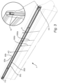
- a barrier 300 comprising a plurality of barrier elements 1, 2.
- the barrier elements 1, 2 are arranged one after the other along a longitudinal direction L.
- the barrier elements 1, 2 are interconnected via respective coupling elements 10, 110, 210.
- Respective barrier element 1, 2 is provided with a coupling element 1, 110, 210 at both respective ends thereof.
- the respective barrier element 1 is designed such that the first coupling element 10 is positioned and oriented as viewed towards a first end of the barrier 1, 2 equal to a position and orientation of the second coupling element 110 as viewed towards a second end of the barrier 1 such that the barrier element 1 presents a coupling element 10, 110 of the same position and orientation independently of if the first end or the second end is presented to another barrier element 2.
- a coupling element 10 provided at an end of a first barrier element 1 will be disclosed in detail.
- the barrier 300 is formed of a plurality of such barrier elements 1 arranged one after the other.
- the disclosure related to the coupling element 10 is equally applicable to the other coupling element 110 of the first barrier element 1 and is also applicable to the other barrier elements 2 forming the barrier 300.
- the barrier 300 may extend several kilometers formed of such barrier elements 1, 2 arranged one after the other. It may also be noted that the barrier 300 may be provided with other kind barrier elements e.g., at ends of the barrier.
- the coupling element 10 is preferably partially embedded in the body of the barrier element 1.
- the body of the barrier element 1, 2 is typically formed of concrete.
- the body of the barrier element 1 is elongated and has an essentially triangularly shaped cross-section with one side forming the base resting on the road or ground and one pointy end forming an upper edge of the barrier element 1.
- the upper end has a cross-section shaped with an at least partly rectangular shape on top of the triangle rather than just ending as a corner of the triangle.
- the first and second coupling elements 10, 110 are preferably interconnected via one or more interconnecting rods 90a-d extending within said body of concrete.
- the interconnecting rods 90a-d are fixed to the respective coupling element 10, 110, such as by welding.
- the coupling elements 10, 110 and the interconnecting rods 90a-d are located in an upper portion of the cross-section of the barrier element 1.
- the coupling elements 10, 110 and the interconnecting rods 90a-d are located in the upper most 50%, preferably upper most 30%, of the height H of the barrier element 1.
- the end of the body of the barrier element 1 is provided with a recess 1a and the coupling element 10 is slightly withdrawn backwardly into the body of the barrier element 1. In the preferred embodiment, it is withdrawn such that the coupling element 210 of the other barrier element 2 will extend slightly past the end face of the barrier element 1.
- the coupling element 10 has, as seen along the longitudinal direction L, an attachment portion 20 by which the coupling element 10 is configured to be attached to the barrier element 1, and a coupling portion 30 by which the coupling element 10 is configured to couple with a corresponding coupling element 210 of the second barrier element 2. As indicated in Fig. 2 , the coupling element 10 may be positioned such that a rear most part of the coupling portion 30 is partially embedded in the body of the barrier element 1.
- the attachment portion 20 is preferably fully embedded in the body of the barrier element 1.
- the attachment portion 20 preferably has, as seen from above V, a cross-section which comprises a first and a second longitudinally extending leg 21, 22.
- the longitudinally extending legs 21, 22 arranged at a mutual transverse distance TD2122 from each other.
- the coupling element 10 has a uniform cross-section along the height direction HD or alternatively expressed along the vertical direction V.
- the legs 21, 22 are basically shaped as two plates extending along the complete height of the coupling element 10.
- FIGs. 3 , and 4a-c there are four interconnecting rods 90a-d extending along each other.
- a first pair of rods 90a-b extend along each other at a mutual distance from each other along the transverse direction T and a second pair of rods 90c-d extend along each other at a mutual distance from each other along the transverse direction T.
- the first pair of rods 90a-b extends at a first height H90a and the second pair of rods 90c-d extends at a second height H90c such that there is along the height direction formed a distance between the rods 90a-b of the first pair and the rods 90c-d of the second pair.
- the interconnecting rods 90a-d are positioned on top of and beneath the respective leg 21, 22, respectively, such that there is an overlap in extension between the interconnecting rods 90a-d and the respective leg 21, 22. This facilitates provision of a strong connection, such as a strong weld.
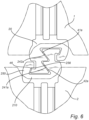
- the coupling portion 30 has a cross-section which comprises a first longitudinal protrusion 40 and a second longitudinal protrusion 50 being arranged at a mutual transverse distance TD from each other.
- the first protrusion 40 may also be referred to as a leg or shank, especially considering that it has an extension along the longitudinal direction L being greater than its extension along a transverse direction T.
- inner or central In view of its position in the coupling it may also be labelled as inner or central. Thus, it may e.g., be referred to as central longitudinal protrusion 40, central leg 40, or the like.
- the second protrusion 50 may also be referred to as hook 50 considering its basic shape. In view of its position in the coupling it may also be labelled as outer. Thus, it may e.g., be referred to as outer longitudinal protrusion 50, outer hook 50, outer longitudinal hook 50, or the like.
- the first and second longitudinal protrusions 40, 50 form between them an open recess 60.
- the open recess 60 has a transversely wide bottom portion 61 and a transversely narrow mouth portion 62.
- the open recess 60 is configured to receive, by a relative vertical movement between the first and second barrier elements 1, 2, a first protrusion 240 of the corresponding coupling element 210 of the second barrier element 2.
- the first protrusion 40 has a first portion 41 and a second portion 42 arranged one after the other along the longitudinal direction L.
- the first portion 41 has on an inner side a first inclined abutment surface 41a.
- the first inclined abutment surface 41a faces in a normal direction N41 which has a component along the transverse direction T being directed towards the second protrusion 50 and a component along the longitudinal direction L being directed towards the attachment portion 20.
- the second portion 42 has on an inner side a second inclined abutment surface 42a.
- the second inclined abutment surface 42a faces in a normal direction N42 which has a component along the transverse direction T being directed towards the second protrusion 50 and a component along the longitudinal direction L being directed towards the attachment portion 20.
- the first inclined abutment surface 41a is configured to abut a second abutment surface 242a of the coupling element 210 of the second barrier element 2 and the second inclined abutment surface 42a is configured to abut a first abutment surface 241a of the coupling element 210 of the second barrier element 2.
- first and second inclined abutment surfaces 41a, 42a each form an angle ⁇ relative to the transversal direction T.
- the angle ⁇ is between 40-65°, more preferably between 45-60°.
- the first inclined abutment surface 41a is angled an angle ⁇ between 50-55° and the second inclined abutment surface 42a is angled an angle ⁇ between 51-56°, preferably with the second inclined abutment surface 42a being angled about 0-2° more than the first inclined abutment surface 41a.
- first and second inclined abutment surfaces 41a, 42a are interconnected by a surface 43, which preferably is a transversally extending surface.
- first and second inclined abutment surfaces 41a, 42a have essentially the same transversal extension, but they are located at two different longitudinal positions. It may also be expressed as that the first and second inclined abutment surfaces 41a, 42a form, as seen along the longitudinal direction, a first slope from a first transversal position at the wide bottom portion 61 of the recess 60 to a second transversal position at the narrow mouth portion 62 of the recess followed by a step back to the first transversal position formed by the surface 43, and then a second slope once again from the first transversal position to the second transversal position.
- the first inclined abutment surface 41 forms part of one side of the recess 60 having the transversely wide bottom portion 61 and the transversely narrow mouth portion 62.
- the second portion 42 has a transversely narrow root portion 42b and a transversely wide end portion 42c allowing the second portion 42 to be received, by a vertical relative movement between the first and second barrier elements 1, 2, in an open recess 260 of the coupling element 210 of the second barrier element 2 having a transversely wide bottom portion 261 and a transversely narrow mouth portion 262 and preventing the second portion 42 from being removed from said recess 260 of the coupling element 210 of the second barrier element 2 in a longitudinal relative movement.
- the coupling elements 10, 210 of the two neighboring barrier elements 1, 2 are configured to be coupled together by one of the barrier elements, such as the second barrier element 2, being moved vertically relative to the other barrier element 1.
- the barrier elements 1, 2 are moved into the intended position one after the other by a crane or the like.
- the barrier elements 1, 2 are lifted up from a trailer or the like and are lowered into position such that the coupling element 210 of the second barrier element 2 becomes coupled with the coupling element 10 of the first barrier element 1.
- the cross-section disclosed is as seen from above, i.e., typically downwardly along vertical.
- the second protrusion 50 has on a side forming part of the recess 60 a hook portion 56.
- the hook portion 56 has an abutment surface 56a which faces in a direction N56a which has a component along the transverse direction T being directed away from the first protrusion 40 and a component along the longitudinal direction L being directed towards the attachment portion 20.
- the transversely narrow root portion 42b of the second portion 42 is formed by the second portion 42 being provided with a recess 47 on an outer side of the second portion 42 and by the second inclined abutment surface 42 on an inner side of the second portion 42.
- the recess 47 allows a portion 256 of the second protrusion 250 of the other coupling element 210 to extend around the transversely wide end portion 42c of the first protrusion 40.
- the transversely wide end portion 42c of the second portion 42 is formed by a transversely extending protrusion 48 on an outer side of the second portion 42 and by the second inclined abutment surface 42 on an inner side of the second portion 42.
- the protrusion 48 may also be said to form the basis of the hook portion 46 or that the hook portion 46 forms part of the protrusion 48.
- the abutment surface 46a of the hook portion 46 forms part of the recess 47.
- the angle ⁇ of the first and second inclined abutment surfaces 41a, 42a relative to the transversal direction T may e.g., be between 40-65°, preferably between 45-60°.
- the angle ⁇ of the first inclined abutment surface 41a may be the same or may be different from the angle ⁇ of the second inclined abutment surface 42a. It is preferred that if the inclined abutment surfaces 41a, 42a have different angles ⁇ the difference between them is less than 5°.
- the inclined surfaces 41a, 42a are inclined such that their respective angle is in the neighborhood of about 45°; slightly below or a bit larger than 45°, preferably between 40-65°. It is more preferred that the angle ⁇ is between 45-60°. It may in this context be noted that it is more preferred that the angle ⁇ is greater than 45° but not too large, i.e., greater than 45° but only up to 65°, preferably only up to 60°.
Landscapes
- Engineering & Computer Science (AREA)
- Architecture (AREA)
- Civil Engineering (AREA)
- Structural Engineering (AREA)
- Connection Of Plates (AREA)
Priority Applications (1)
| Application Number | Priority Date | Filing Date | Title |
|---|---|---|---|
| EP23200834.2A EP4530403A1 (de) | 2023-09-29 | 2023-09-29 | Kopplungselement, barriereelement und barriere |
Applications Claiming Priority (1)
| Application Number | Priority Date | Filing Date | Title |
|---|---|---|---|
| EP23200834.2A EP4530403A1 (de) | 2023-09-29 | 2023-09-29 | Kopplungselement, barriereelement und barriere |
Publications (1)
| Publication Number | Publication Date |
|---|---|
| EP4530403A1 true EP4530403A1 (de) | 2025-04-02 |
Family
ID=88241467
Family Applications (1)
| Application Number | Title | Priority Date | Filing Date |
|---|---|---|---|
| EP23200834.2A Pending EP4530403A1 (de) | 2023-09-29 | 2023-09-29 | Kopplungselement, barriereelement und barriere |
Country Status (1)
| Country | Link |
|---|---|
| EP (1) | EP4530403A1 (de) |
Citations (4)
| Publication number | Priority date | Publication date | Assignee | Title |
|---|---|---|---|---|
| EP1467028B1 (de) * | 2003-04-12 | 2007-08-01 | Nordbeton GmbH | Flächentrennelement, das als auf eine Unterlage aufstellbarer Wandabschnitt ausgebildet ist |
| US8388257B2 (en) | 2008-11-20 | 2013-03-05 | Rebloc Gmbh | Connecting device for connecting separating elements for traffic areas |
| WO2016011465A1 (de) * | 2014-07-23 | 2016-01-28 | Kirchdorfer Fertigteilholding Gmbh | Leitwandelement |
| DE102016006697A1 (de) * | 2016-05-31 | 2017-11-30 | Hermann Spengler Gmbh & Co. Kg | Fahrspurtrenneinrichtung |
-
2023
- 2023-09-29 EP EP23200834.2A patent/EP4530403A1/de active Pending
Patent Citations (4)
| Publication number | Priority date | Publication date | Assignee | Title |
|---|---|---|---|---|
| EP1467028B1 (de) * | 2003-04-12 | 2007-08-01 | Nordbeton GmbH | Flächentrennelement, das als auf eine Unterlage aufstellbarer Wandabschnitt ausgebildet ist |
| US8388257B2 (en) | 2008-11-20 | 2013-03-05 | Rebloc Gmbh | Connecting device for connecting separating elements for traffic areas |
| WO2016011465A1 (de) * | 2014-07-23 | 2016-01-28 | Kirchdorfer Fertigteilholding Gmbh | Leitwandelement |
| DE102016006697A1 (de) * | 2016-05-31 | 2017-11-30 | Hermann Spengler Gmbh & Co. Kg | Fahrspurtrenneinrichtung |
Similar Documents
| Publication | Publication Date | Title |
|---|---|---|
| US4059362A (en) | Concrete highway traffic barricade having integrally formed coupling | |
| US4113400A (en) | Impact resistant tongue-and-groove coupling for highway traffic barricades | |
| US6164865A (en) | Interlocking barrier system with multiple securing mechanisms | |
| EP4121602B1 (de) | Verkehrsbarriere mit trägheitsaufpralltafeln und schallbarriere | |
| EP2087175B1 (de) | Leitplankenbalken | |
| EP2414591B1 (de) | Sicherheitsstruktur für einen schienenstrang | |
| CA1036381A (en) | Anchor insert for embedment in a concrete slab | |
| ES2939934T3 (es) | Barrera de tráfico móvil | |
| US20250250753A1 (en) | Systems, Devices, and/or Methods for Managing Traffic | |
| EP3880919B1 (de) | Fahrbahnbegrenzungsvorrichtung | |
| CA2634087C (en) | Improved interlocking highway structure | |
| EP4530403A1 (de) | Kopplungselement, barriereelement und barriere | |
| JP2003514149A (ja) | 足場要素を結合させるためのデバイス | |
| JP2020084484A (ja) | 連結具及び連結具を有する構造物 | |
| EP1903156A2 (de) | Verbindungssystem, einzelne Elemente und Verwendungsverfahren dafür | |
| US20060072967A1 (en) | Transition structure | |
| US20230068991A1 (en) | Barrier element to block traffic and/or as a security precaution including a ballast compartment | |
| US20090297263A1 (en) | Betonleitwand-element | |
| KR101825387B1 (ko) | 연성토용 지주 및 상기 지주를 이용한 시공방법 | |
| JP7306644B2 (ja) | 防護柵 | |
| JP7213502B2 (ja) | 防護柵 | |
| CN115461510A (zh) | 安全护栏 | |
| CN109267478B (zh) | 一种稳定面板座及接缝模块及一种轨道梁接缝装置 | |
| CA1082969A (en) | Tongue-and-groove coupling for highway traffic barricade | |
| WO2010059995A1 (en) | Energy absorbing system with anchor net |
Legal Events
| Date | Code | Title | Description |
|---|---|---|---|
| PUAI | Public reference made under article 153(3) epc to a published international application that has entered the european phase |
Free format text: ORIGINAL CODE: 0009012 |
|
| STAA | Information on the status of an ep patent application or granted ep patent |
Free format text: STATUS: THE APPLICATION HAS BEEN PUBLISHED |
|
| AK | Designated contracting states |
Kind code of ref document: A1 Designated state(s): AL AT BE BG CH CY CZ DE DK EE ES FI FR GB GR HR HU IE IS IT LI LT LU LV MC ME MK MT NL NO PL PT RO RS SE SI SK SM TR |
|
| STAA | Information on the status of an ep patent application or granted ep patent |
Free format text: STATUS: REQUEST FOR EXAMINATION WAS MADE |
|
| 17P | Request for examination filed |
Effective date: 20250923 |
|
| GRAP | Despatch of communication of intention to grant a patent |
Free format text: ORIGINAL CODE: EPIDOSNIGR1 |
|
| STAA | Information on the status of an ep patent application or granted ep patent |
Free format text: STATUS: GRANT OF PATENT IS INTENDED |
|
| INTG | Intention to grant announced |
Effective date: 20260128 |
|
| GRAS | Grant fee paid |
Free format text: ORIGINAL CODE: EPIDOSNIGR3 |
|
| GRAA | (expected) grant |
Free format text: ORIGINAL CODE: 0009210 |
|
| STAA | Information on the status of an ep patent application or granted ep patent |
Free format text: STATUS: THE PATENT HAS BEEN GRANTED |