EP4530404A1 - Balayeuse et procédé de fonctionnement d'une balayeuse - Google Patents
Balayeuse et procédé de fonctionnement d'une balayeuse Download PDFInfo
- Publication number
- EP4530404A1 EP4530404A1 EP24201466.0A EP24201466A EP4530404A1 EP 4530404 A1 EP4530404 A1 EP 4530404A1 EP 24201466 A EP24201466 A EP 24201466A EP 4530404 A1 EP4530404 A1 EP 4530404A1
- Authority
- EP
- European Patent Office
- Prior art keywords
- flap
- sweeping
- actuator device
- sweepings
- installation plane
- Prior art date
- Legal status (The legal status is an assumption and is not a legal conclusion. Google has not performed a legal analysis and makes no representation as to the accuracy of the status listed.)
- Granted
Links
Images


Classifications
-
- E—FIXED CONSTRUCTIONS
- E01—CONSTRUCTION OF ROADS, RAILWAYS, OR BRIDGES
- E01H—STREET CLEANING; CLEANING OF PERMANENT WAYS; CLEANING BEACHES; DISPERSING OR PREVENTING FOG IN GENERAL CLEANING STREET OR RAILWAY FURNITURE OR TUNNEL WALLS
- E01H1/00—Removing undesirable matter from roads or like surfaces, with or without moistening of the surface
- E01H1/02—Brushing apparatus, e.g. with auxiliary instruments for mechanically loosening dirt
- E01H1/04—Brushing apparatus, e.g. with auxiliary instruments for mechanically loosening dirt taking- up the sweepings, e.g. for collecting, for loading
- E01H1/045—Brushing apparatus, e.g. with auxiliary instruments for mechanically loosening dirt taking- up the sweepings, e.g. for collecting, for loading the loading means being a rotating brush with horizontal axis
-
- E—FIXED CONSTRUCTIONS
- E01—CONSTRUCTION OF ROADS, RAILWAYS, OR BRIDGES
- E01H—STREET CLEANING; CLEANING OF PERMANENT WAYS; CLEANING BEACHES; DISPERSING OR PREVENTING FOG IN GENERAL CLEANING STREET OR RAILWAY FURNITURE OR TUNNEL WALLS
- E01H1/00—Removing undesirable matter from roads or like surfaces, with or without moistening of the surface
- E01H1/02—Brushing apparatus, e.g. with auxiliary instruments for mechanically loosening dirt
- E01H1/05—Brushing apparatus, e.g. with auxiliary instruments for mechanically loosening dirt with driven brushes
- E01H1/053—Brushing apparatus, e.g. with auxiliary instruments for mechanically loosening dirt with driven brushes having vertical axes
Definitions
- the invention further relates to a method for operating a sweeper.
- the JP H05-321 219 A discloses a floor cleaning vehicle for cleaning a floor surface.
- the DE 699 08 720 T2 discloses cleaning machines, in particular so-called “over-the-top” cleaning machines.
- the DE 10 2014 102 540 A1 discloses a sweeper comprising a chassis for moving on a floor surface, a sweeping roller sweeping according to the overhead sweeping principle for cleaning the floor surface, a coarse sweeping material cover having a sweeping threshold, wherein the sweeping threshold is arranged in front of the sweeping roller in a main direction of movement of the sweeper and partially covers the sweeping roller in a covering position of the coarse sweeping material cover, and an actuating unit for transferring the coarse sweeping material cover from the covering position into a release position.
- the DE 26 29 967 A1 discloses a dust filter device for sweeping and floor cleaning machines.
- the EP 0 578 442 A1 reveals a sweeper based on the front loader principle.
- More sweepers are in the EP 0 606 713 A1 , US 4,206,530 A , US 2002/0138939 A1 , EP 1 612 335 A2 and WO 2016/166616 A1 revealed.
- the DE 44 16 132 A1 discloses a suction device for sweeping vehicles.
- the DE 196 31 536 A1 discloses a method for cleaning surfaces by means of a self-collecting, pneumatically operating sweeper with a suction nozzle for picking up the sweeping material, which is arranged on a suction shaft and sucks the sweeping material into the sweeper.
- More sweepers are in the EP 1 612 335 A2 , the US 3,233,274 A , the WO 2004/071654 A2 , the US 8,458,855 B2 , the EP 1 535 564 A2 , the WO 2019/149343 A1 and the US 5,940,928 A revealed.
- the invention is based on the object of providing a sweeper of the type mentioned above which enables an optimized cleaning result for a floor to be cleaned.
- the at least one flap has at least one third position in which the at least one flap is raised relative to the installation plane and a passage for sweeping material to the at least one sweeping roller is formed between the at least one flap and the installation plane, and in that a second actuator device for bringing the at least one flap into the at least one third position is assigned to the at least one flap.
- the at least one flap is in the second position.
- garbage that is in front of the flap with respect to the sweeper's direction of travel and is of a corresponding size cannot reach the at least one sweeping roller due to the position of the flap with the flap as a blocking surface.
- At least one third position of the at least one flap is provided, which opens the passage for sweepings to the at least one sweeping roller. This allows the sweepings to reach the sweeping roller below the at least one flap and then be transported accordingly (particularly after the at least one flap has been returned to the second position) into the at least one sweepings container.
- the solution according to the invention allows, in addition to “dust sweeping”, also "light waste” to be removed from the floor to be cleaned. By temporarily lifting the at least one flap and holding it in at least one third position, this light waste can reach the sweeping roller and from there be transported into the at least one sweeping waste container.
- the at least one flap in the second position touches the installation plane with a front end or at least has only a small distance, then sweepings can be transported through the at least one flap and through the opening into the sweepings container in the manner of a dustpan.
- the at least one flap preferably forms a guide device for directing sweepings into the at least one sweepings hopper. It forms a sweeping blade, which in particular rests against the installation plane and thus against the floor to be cleaned, in order to be able to convey sweepings into the sweepings in a defined manner.
- the at least one flap forms a ramp (inclined plane) towards the at least one sweepings hopper.
- a targeted transport of sweepings into the sweepings container can be achieved by means of an area made of flexible material, which is designed in particular as a lip and in particular as a contact lip on a floor to be cleaned.
- At least one flap can be implemented as a dustpan or as a "feed ramp" for sweepings.
- a dustpan By arranging a pivot bearing in the area of the underside of at least one opening, a dustpan can be easily implemented via the flap.
- the at least one flap has a number of functions, namely, firstly, as a closure element when the at least one flap is in the first position. In the second position, the at least one flap forms a type of dustpan for transporting debris into the debris container and for guiding the debris in a defined manner.
- the sweeper has a forward direction of travel and the at least one sweeping roller rotates in a direction parallel to the forward direction of travel on the floor to be cleaned. This allows sweepings to be transported into the at least one sweepings container in a targeted manner using the sweeping bucket principle.
- the sweeper has a front end and the at least one flap is positioned between the front end and the at least one sweeping roller.
- a sweeper is also referred to as a front-loading machine.
- the rotational speed of the at least one sweeping roller can be kept relatively low, and a The sweeping path can be kept short, resulting in low-dust sweeping and reduced roller wear.
- a passage for "light waste” can be achieved to allow for a stop.
- the at least one third position can be reached quickly in time from the second position and the second position can then also be reached quickly in time from the at least one third position.
- At least one third position can be reached quickly, and from at least one third position, the second position, for example, can be quickly reached.
- the flap it is possible for the flap to be pivotably driven, for example, directly via an electric motor.
- a lever mechanism and/or linkage mechanism is hinged to the at least one flap, which is coupled to the first actuator device. This allows for a simple movement of the at least one flap, in particular between the first position and the second position.
- the second actuator device is coupled to the first actuator device, in particular mechanically coupled. This allows at least one third position to be achieved through the action of the second actuator device on the first actuator device, or it allows a simple transition from the at least one third position to the second position.
- the second actuator device is designed and/or arranged in such a way that, starting from the second position of the at least one flap, it brings the at least one flap into the at least one third position, and/or starting from the at least one third position, it brings the at least one flap into the second position.
- the starting point for the at least one third position is then the second Position. This makes it easy to clear the passage so that "light waste" can reach at least one sweeping roller.
- the first actuator device is hinged to the second actuator device. This results in a structurally simple design.
- the first actuator device has a base and at least one movement element, wherein the at least one movement element is movable (relative to the base) and in particular displaceable, and the at least one movement element is articulated to the at least one flap or to a lever mechanism and/or linkage mechanism for the at least one flap. This allows a pivoting movement of the flap to be easily implemented, in particular for bringing it into the first position and the second position.
- the second actuator device is coupled to the base and, in particular, causes a joint movement of the combination of the base and at least one movement element.
- the second actuator device mediated by the first actuator device, can move the at least one flap and bring it into or out of the at least one third position.
- the second actuator device is coupled to the first actuator device in such a way that the first actuator device as a whole is moved via the second actuator device.
- the second actuator device then moves the first actuator device, and this movement of the first actuator device as a whole in turn causes a pivoting movement of the at least one flap, wherein the at least one flap is then brought into the at least one third position.
- the first actuator device comprises at least one pneumatic cylinder or hydraulic Cylinder.
- the first actuator device can also be formed by an electric motor.
- the second actuator device comprises an electric motor or in particular a linear motor.
- At least one bridge element is provided, which is positioned so as to be movable and, in particular, pivotable relative to the chassis, wherein the first actuator device and the at least one bridge element are articulated, and wherein the second actuator device is coupled to the at least one bridge element, and wherein a movement of the at least one bridge element can be effected by the second actuator device, which movement leads to a movement of the first actuator device.
- the second actuator device can then move the bridge element itself (unfixing it) in order to effect a pivoting movement into the at least one third position of the at least one flap. This makes it possible, for example, to easily activate a pivoting movement into the at least one third position starting from the second position of the at least one flap by the second actuator device.
- the second actuator device causes a movement, and in particular a pivoting movement, of the at least one bridge element starting from an initial position of the at least one bridge element.
- the second actuator device is not activated and, in particular, at least one movable bridge element, to which the first actuator device is coupled, is fixed in an initial position. This results in a mechanically simple design.
- the second position is the operative position for sweeping.
- the passage to the at least one sweeping roller is temporarily (and in particular, relatively briefly) opened.
- the operating device for the second actuator device comprises a button, wherein by pressing and holding the button, the at least one flap is moved into and held in the at least one third position, and upon termination of the button holding, the at least one flap automatically moves from the at least one third position to the second position.
- This allows an operator to temporarily set the at least one third position of the at least one flap if, for example, they detect that light waste is being moved by the sweeper.
- the sweepings receiving device has a first side wall and an opposite second side wall, wherein the at least one flap is positioned between the first side wall and the second side wall, wherein the first side wall has a first end facing the at least one sweeping roller, and the second side wall has a second end facing the at least one sweeping roller, and the at least one opening is set back from the first end and the second end in a direction which is transverse to the axis of rotation of the at least one sweeping roller.
- This makes it easy to arrange, for example, a pivot bearing for the at least one flap in a protected manner. Furthermore, this makes it possible to keep dust pollution in the environment to a minimum.
- At least one side brush is mounted on the chassis. This results in a "broadening" of the cleaning area over a corresponding length (parallel to the axis of rotation) of at least one sweeping roller.
- a sensor device that monitors a space for the accumulation of debris, wherein the space in front of the at least one flap is located in front of the passage.
- the sensor device can check whether debris is accumulating or has accumulated in front of the at least one flap (particularly when the flap is in the second position).
- the sensor device is, for example, an optical sensor device and includes a camera.
- the sensor device provides, for example, the possibility of indicating to an operator of the sweeper that debris has accumulated, allowing the operator to intervene and, in particular, manually activate the second actuator device. It also provides the possibility of automatically activating the second actuator device to move the at least one flap into at least one third position.
- the sensor device is mounted on the chassis with a field of view facing the installation plane. This allows for monitoring the accumulation of garbage on the floor to be cleaned in the space in front of the passage (with the at least one flap in the second position).
- a control device is provided to which the sensor device is signal-effectively coupled and which controls the second actuator device and, in particular, controls it automatically.
- the sensor device supplies its sensor signals to the control device.
- the sensor signals are evaluated, in particular, in an evaluation unit of the control device. For example, an evaluation is carried out by image processing if the sensor device provides optical data.
- the second actuator device can then be activated via the control device and, in particular, automatically activate, in particular to bring at least one flap into at least one third position.
- control device automatically activates the second actuator device to move the at least one flap into the at least one third position. This allows such accumulated sweepings to enter the passage by driving over it and be conveyed into the at least one sweeping container by the at least one sweeping roller.
- the at least one third position is held for a specific period of time, which in particular is no more than 30 seconds, and then the at least one flap is automatically moved to the second position by a control device.
- a control device This allows accumulated debris to be collected within a relatively short period of time, and the "normal" sweeping process (with the at least one flap in the second position) can then be resumed.
- the at least one flap is automatically moved to the at least one third position for a specific, relatively short period of time and then returned to the second position.
- At least one flap is located between the first side wall and the second side wall. This protects it from the sides of the sweeper.
- a method of the type mentioned at the outset in which the at least one flap is brought into the at least one third position in order to ensure the passage for sweepings between the at least to open a flap and the installation level to the at least one sweeping roller, and then the at least one flap is brought into the second position in order to bring sweepings into the at least one sweepings container.
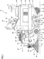
- the chassis 12 carries a driving device 14.
- the driving device 14 enables the sweeper 10 to be set up on a floor 16 to be cleaned and to be driven over this.
- the driving device 14 defines a mounting plane 18 for positioning the sweeper 10 on the floor 16 to be cleaned. If the floor 16 to be cleaned is flat, then the mounting plane 18 coincides with a corresponding surface of the floor 16 to be cleaned.
- the chassis 12 has a bottom side 24 which faces the installation plane 18.
- the sweeper 10 comprises (at least) one sweeping roller 26, which is arranged on the chassis 12 and is positioned on the underside 24 of the chassis 12 or between the installation plane 18 and the underside 24.
- the rotation axis 28 is oriented parallel to the installation plane 18.
- the front wheel assembly 20 and the rear wheel assembly 22 have wheel axles that are also parallel to the mounting plane 18.
- the rotation axis 28 is parallel to these wheel axles.
- the sweepings receiving device 54 with the sweepings container 44 is located in the region of the front end 34 of the sweeping machine 10.
- the front end 34 is formed on the sweepings receiving device 54.
- the first side wall 70 has a first front end 84 (compare Figure 3 ), which is assigned to the sweeping roller 26. Accordingly, the second side wall has a second front end.
- the opening 82 is formed between the first side wall 70 and the opposite second side wall and extends, for example, over the entire width of the sweepings receiving device 54 between the first side wall 70 and the opposite second side wall, or over a partial area relative to this width (in a direction parallel to the rotation axis 28).
- the opening 82 is positioned away from the underside of the chassis 12 (towards the installation plane 18) and is arranged in front of the sweeping roller 26 (relative to the direction from the rear end 36 to the front end 34) in order to be able to throw sweepings into the sweepings hopper 44 through the opening 82.
- the opening 82 is positioned between the left and right front wheels of the front wheel assembly 20.
- the opening 82 has a bottom side 88 which faces the installation plane 18 (compare Figures 3 and 6 ), and an opposite top 90.
- a flap 92 is located on the debris collection device 54 in the area of the opening 82.
- the flap 92 is pivotally mounted about a pivot axis 96 via a pivot bearing 94.
- the pivot axis 96 is parallel to the installation plane 18 and parallel to the rotation axis 28.
- the pivot bearing 94 is located on the bottom 92 of the sweepings receiving device 54 and thus in the area of the underside 88 of the opening 82.
- the flap 92 is covered laterally outwardly at least in a partial area by the side skirts 86 of the first side wall 70 and the second side wall and is thus also protected.
- the flap 92 has several functions, which are explained below. In particular, one function of the flap 92 is determined by its pivoting position on the pivot bearing 94.
- the flap 92 has a bottom 98.
- the bottom 98 is made of a rigid material such as a metal material or plastic material.
- a region 100 made of a flexible material is arranged on the floor 98. This region 100 forms a front end 102 of the flap 92. This front end 102 faces the sweeping roller 26.
- the flap 92 can be placed against the floor 16 to be cleaned via the region 100.
- the area 100 is made, in particular, of a rubber material.
- the area 100 forms a contact lip of the flap 92 against the floor 16 to be cleaned.
- Spaced-apart side walls 104 are located on the base 98.
- the side walls 104 extend transversely and, in particular, vertically from the base 98. They do not protrude into the area 100.
- the side wall 104 has a triangular shape (compare Figures 3 and 6 ), with a first leg 106 and a second leg 108.
- the first leg 106 and the second leg 108 each originate from the base 98 and from opposite ends of the base 98 and then intersect.
- the first leg 106 is shorter than the second leg 108, with the first leg 106 bordering the area 100 and the second leg 108 leading to the area at the pivot bearing 94.
- the flap 92 Relative to the side wall 104 and a distance above the floor 98, the flap 92 has a greater height at the area 100 than in the area of the pivot bearing 94, this height decreasing continuously from the area 100 towards the pivot bearing 94.
- the bottom 98 of the flap 92 forms a guide surface for the debris to be transported into the debris container 44.
- the side walls 104 form guide stops to hold the debris laterally (in the flap 92) and prevent it from falling out. This, in turn, enables essentially all the sweepings that reach the flap 92 are also transported into the sweepings container 44.
- the flap 92 with its flexible area 100 forms a type of dustpan or ramp during sweeping operation of the sweeper 10.
- the sweeper 10 includes a movement mechanism 110 for the flap 92.
- the movement mechanism 110 in turn includes a lever mechanism or linkage mechanism 112.
- the movement mechanism 110 comprises a first part, which is assigned to a side wall 104, and a second part, which is assigned to the corresponding opposite side wall.
- the first part and the second part are basically of the same design, wherein in the Figures 1 to 5 only a part is shown.
- the corresponding movement mechanism 110 is arranged outside the dirt container 44 and is positioned, for example, in a space between the dirt container 44 and the corresponding first side wall 70 (first part) or the second side wall (second part), at least in a partial area.
- first part or second part When describing the elements of the movement mechanism 110 below, reference is made to one part (first part or second part). The corresponding elements are then also present in the other part. The first part and the second part are synchronized.
- the movement mechanism 110 comprises a bridge element 114.
- the bridge element 114 is movably mounted with respect to the chassis 12.
- the bridge element 114 is pivotally mounted.
- the pivot bearing 116 is attached to the corresponding first side wall 70. or second side wall.
- a pivot axis 118 is parallel to the installation plane 18 or parallel to the rotation axis 28 of the sweeping roller 26.
- the bridge element 114 has an initial position 120 ( Figures 3 , 4 ), which is a basic position of the bridge element 114.
- a first actuator device 122 is coupled to the bridge element 114.
- the first actuator device is, in particular, a hydraulic or pneumatic cylinder 124 with a base 126 and a movement element 128 (cylinder piston).
- the cylinder 124 is pivotally coupled to the bridge element 114 via the base 126, with a pivot axis parallel to the pivot axis 118.
- a corresponding coupling point 129 is spaced apart from the pivot bearing 116.
- the moving element 128 (the piston) is hinged at its end to a first web 130.
- the first web 130 is hinged to a pivot bearing 132, which is fixedly positioned relative to the chassis 12.
- a rotation axis of the pivot bearing 132 is parallel to the pivot axis 118.
- the first web 130 is connected to a second web 134, and in particular is connected in a rotationally fixed manner.
- pivoting of the first web 130 on the pivot bearing 132 (and relative to the movement element 128) causes a coordinated and, in particular, synchronous movement of the second web 134.
- a third web 136 is hinged to the second web 134 via a pivot bearing 138.
- a rotation axis of the pivot bearing 138 is parallel to the pivot axis 118.
- the third web 136 is hinged to the flap 92, and in particular to the corresponding side wall 104, via a pivot bearing 140.
- a rotation axis of the pivot bearing 140 is parallel to the pivot axis 118.
- the pivot bearing 138 allows the distance between the pivot bearing 132 and the pivot bearing 140 to be adjusted depending on the rotational position of the first web 130.
- the corresponding rotational position of the first web 130 is in turn adjusted by the first actuator device 122 and thereby by the linear position of the movement element 128.
- a corresponding pivot position of the flap 92 on the pivot axis 96 can be adjusted via the actuator device 122.
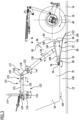
- FIG 4 A first position 142 of the flap 92 is shown. In this first position 142, the flap 92 is pivoted away from the installation plane 18, and the opening 82 is closed by the flap 92 toward the installation plane 18 and toward the sweeping roller 26.
- the first position 142 of the flap 92 is not a cleaning operating position.
- the first position 142 for the flap 92 is set particularly for a non-cleaning travel of the sweeper 10 to or from a work site.
- the first position 142 of the flap 92 is reached when the movement element 128 is extended to the base 126 ( Figure 4 ). This means that compared to the retracted position (compare Figure 3 ; see below) a distance of a linkage point 144 of the first web 130 to the movement element 128 to the linkage point 129 is greater than in a second position 146 of the flap 92 (compare Figure 3 ).
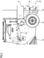
- the second position 146 of the flap 92 ( Figure 3 ) is an operational position for a cleaning company.
- the movement element 128 is retracted (the distance between the articulation point 144 and the articulation point 129 is, in particular, minimized).
- the first web 130, the second web 134, and the third web 136 lie on a straight line.
- the flap 92 is pivoted towards the installation plane 18 and, in particular, the area 100 then touches the floor 16 to be cleaned.
- the flap 92 is positioned relative to the installation plane 18 such that the bottom 98 of the flap 92 is at an acute angle to the installation plane 18 and forms an inclined plane to the floor 16 to be cleaned.
- the flap 92 then forms a ramp over its bottom 98.
- the bottom 98 has a decreasing distance from the installation plane 18, starting from the pivot bearing 94 and moving toward the area 100.
- the rotating sweeping roller 26 can pick up sweepings from the floor 16 to be cleaned and throw them in the direction of the opening 82, whereby the flap 92 then forms a guide device for sweepings to be conveyed into the sweepings container 44.
- the flap 92 forms a type of dustpan which, via the area 100 (the flexible lip), rests against the floor 16 to be cleaned (or has at most a minimum distance of, for example, at most 10 mm or less).
- the flap 92 functions as a closure element.
- the flap 92 functions as a sweeping blade, which forms a guide device for the sweeping material path from the sweeping roller 26 through the opening 82 into the sweeping material container 44.
- the bridge element 114 In the first position 142 and the second position 146 of the flap 92, the bridge element 114 is in its initial position 120.
- a space 148 (compare for example Figure 3 ) is present. In the second position 146, this space 148 is blocked by the flap 92 with the area 100 toward the sweeping roller 26.
- this space 148 is open towards the sweeping roller 26.
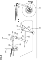
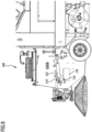
- the flap 92 has (at least) a third position 150 ( Figure 5 ), this third position 150 being located between the first position 142 and the second position 146.
- the flap 92 In the third position 150, the flap 92 is raised relative to the installation plane 18, and the flap 92, with its area 100, does not touch the floor 16 to be cleaned.
- the space 148 is thus open toward the sweeping roller 26; a passage 152 is formed under the debris receiving device 54 and the flap 92 toward the sweeping roller 26.
- a minimum height 154 of this passage 152 is at least 20 mm and in particular at least 25 mm and preferably at least 30 mm.
- the minimum height 154 refers in particular to a minimum distance of the area 100 (for example at a front edge of the area 100 towards the sweeping roller 26) to the installation plane 18.
- sweeping material can pass under the sweeping machine 10 and thereby under the sweeping material receiving device 54 towards the sweeping roller 26 when it is driven over by the sweeping machine 10.
- a second actuator device 156 is provided for setting the third position 150.
- the second actuator device 156 acts on the bridge element 114 and moves the bridge element 114 from its initial position 120 into a corresponding position. This movement of the bridge element 114 from the initial position 120 moves and, in particular, displaces the first actuator device 122, including the base 126 and the movement element 128, as a whole, which in turn affects the first web 130 and thus, in turn, the second web 134 and the third web 136.
- the second actuator device 156 is mechanically coupled to the first actuator device 122 via the bridge element 114. Activation of the second actuator device 156 causes a movement of the first actuator device 122 as a whole and thus a pivoting of the flap 92 about the pivot axis 96. However, the pivoting is such that the passage 152 is opened and the third position 150 is below the first position 142.
- the second actuator device 156 is an electric motor, and in particular a linear motor 158.
- This linear motor 158 has a linearly movable rod 160.
- the rod 160 is coupled to the bridge element 114 at a distance from the pivot bearing 116.
- a displacement position of the rod 160 determines a rotational position of the bridge element 114 on the pivot bearing 116.
- the second actuator device 156 with its linear motor 148 is not active and the rod 160 is positioned so that the bridge element 114 is in its initial position 120 ( Figures 3 , 4 ).
- the rod 160 is moved and pivoted, for example, in the direction of the sweeping roller 26 (compare Figure 5 ) that the first actuator device 122 with the base 126 and the movement element 128 is moved toward the sweeping roller 26.
- This causes the flap 92 to be raised from the second position 146 and brings the flap into the third position 150 with the passage 152 open.
- the third position 150 of the flap 92 was described above. It is generally possible for there to be exactly one third position 150, or for there to be multiple third positions 150. If there are multiple third positions 150, these can be set in steps or continuously.
- the second actuator device 156 is arranged above the first actuator device 122 with respect to a height direction transverse to the installation plane 18.
- the first actuator device 122 and the second actuator device 156 can be activated by the operating device 52.
- the operating device 52 is designed such that permanent operator intervention is necessary to maintain the third position 150.
- the operating device 52 comprises a button 162 (see Figure 1 ), which is assigned to the second actuator device 156.
- the button 162 is not actuated, the bridge element 114 is in its initial position 120.
- the second actuator device 156 is activated accordingly, displacing the rod 160 and pivoting the bridge element 114, as described above.
- the button 162 must remain pressed, and to maintain the third position 150, the button 162 must also remain pressed.
- the rod 160 returns to its initial position (automatically) and the bridge element 114 automatically moves to its initial position 120.
- the flap 92 thereby automatically moves to the second position 146. Therefore, without active operator intervention on the button 162, the flap 92 does not remain in the third position 150.
- the sweeper 10 functions as follows: During a non-cleaning trip, for example to or from a job site, the flap 92 is in the first position 142. This closes the opening 82 by the flap 92 (compare Figure 4 ).
- the flap 92 is moved by the operator to the second position 146 (compare Figure 3 ). Sweepings can then be transported by the sweeping roller 26 (which is lowered onto the floor 16 to be cleaned) through the flap into the sweepings container 44.
- a sensor device 164 (see Figure 3 ) is positioned, which monitors the space 148 for the accumulation of "light waste."
- the sensor device 164 is, for example, an optical sensor device or a camera sensor device.
- the sweeper 10 comprises a control device 166 (see Figure 1 ), which is signal-effectively coupled to the sensor device 164.
- the control device 166 evaluates, in particular, signals from the sensor device 164 regarding an accumulation of "light waste" in the space 148. If an accumulation or excessive accumulation is detected, the control device 166 controls the second actuator device 156, which then briefly moves the flap 92 into the third position 150 in order to open the passage 152 to the sweeping roller 26.
- the third position 160 is held for only a relatively short period of time, for example, 10 s, 20 s, or 30 s. Subsequently, the second actuator device 156 is controlled such that the flap 92 automatically returns to the second position 146.
- FIG. 7 Another embodiment of a sweeper 168, which is shown in the Figures 7 and 8 is basically designed the same as the sweeper 10.
- a second actuator device 170 is provided, which also acts on a bridge element 114', wherein the second actuator device 170 is positioned in particular between the first actuator device 122 and the installation plane 18.
- the second actuator device 170 is, for example, an electric motor which acts directly on the pivot bearing 116 in order to pivot the bridge element 114'.
Landscapes
- Engineering & Computer Science (AREA)
- Architecture (AREA)
- Civil Engineering (AREA)
- Structural Engineering (AREA)
- Refuse Collection And Transfer (AREA)
Applications Claiming Priority (1)
| Application Number | Priority Date | Filing Date | Title |
|---|---|---|---|
| DE102023126063.4A DE102023126063A1 (de) | 2023-09-26 | 2023-09-26 | Kehrmaschine und Verfahren zum Betreiben einer Kehrmaschine |
Publications (2)
| Publication Number | Publication Date |
|---|---|
| EP4530404A1 true EP4530404A1 (fr) | 2025-04-02 |
| EP4530404B1 EP4530404B1 (fr) | 2026-04-08 |
Family
ID=92883006
Family Applications (1)
| Application Number | Title | Priority Date | Filing Date |
|---|---|---|---|
| EP24201466.0A Active EP4530404B1 (fr) | 2023-09-26 | 2024-09-19 | Balayeuse et procédé de fonctionnement d'une balayeuse |
Country Status (2)
| Country | Link |
|---|---|
| EP (1) | EP4530404B1 (fr) |
| DE (1) | DE102023126063A1 (fr) |
Citations (21)
| Publication number | Priority date | Publication date | Assignee | Title |
|---|---|---|---|---|
| US3233274A (en) | 1963-01-28 | 1966-02-08 | Tennant Co G H | Sweeping machine dust separator apparatus |
| FR2006091A1 (fr) * | 1968-04-11 | 1969-12-19 | Tennant Co | |
| DE2629967A1 (de) | 1975-08-13 | 1977-02-17 | Fmc Corp | Staubfiltervorrichtung |
| US4206530A (en) | 1978-01-30 | 1980-06-10 | Tennant Company | Surface maintenance machine having air recirculation |
| JPH05321219A (ja) | 1992-05-20 | 1993-12-07 | Toyota Autom Loom Works Ltd | 床面清掃車 |
| EP0578442A1 (fr) | 1992-07-08 | 1994-01-12 | Tennant Company | Tremie et chambre à filtration pour balayeuse projetant les déchets vers l'avant |
| EP0606713A1 (fr) | 1992-12-14 | 1994-07-20 | Tennant Company | Balayeuse convertible |
| DE4416132A1 (de) | 1994-05-06 | 1995-11-09 | Nkf Leichtmetallbau | Saugeinrichtung für Kehrfahrzeuge |
| DE19631536A1 (de) | 1996-07-25 | 1998-01-29 | Kroll Spezialfahrzeuge Gmbh | Verfahren und Einrichtung zum Säubern von Flächen, insbesondere von Verkehrsflächen, mit einer heterogenen, vorzugsweise gepflasterten Oberfläche |
| US5940928A (en) | 1998-01-15 | 1999-08-24 | Tennant Company | Surface maintenance machine with computer controlled operational and maintenance systems |
| US20020138939A1 (en) | 2001-03-07 | 2002-10-03 | Minuteman International, Inc., (An Illinois Corporation) | Litter vacuum |
| FR2830550A1 (fr) * | 2001-10-05 | 2003-04-11 | Cochet Sa | Balayeuse adaptable a un engin automoteur |
| DE69908720T2 (de) | 1998-08-25 | 2004-04-22 | Tennant Co., Minneapolis | Kehrmaschine mit in mehrere Position versetzbarer vorderer Schürze |
| WO2004071654A1 (fr) | 2003-02-14 | 2004-08-26 | Bussan Nanotech Research Institute Inc. | Procede permettant de former des particules metalliques de catalyseur afin de produire un nanotube de carbone a paroi unique |
| EP1535564A2 (fr) | 2003-11-28 | 2005-06-01 | Alfred Kärcher GmbH & Co. KG | Machine à nettoyer les sols |
| EP1612335A2 (fr) | 2004-06-29 | 2006-01-04 | Schmidt Holding GmbH | Dispositif de balayage automobile |
| US8458855B2 (en) | 2008-02-29 | 2013-06-11 | Tennant Company | Hopper assembly with filter module for surface maintenance machine |
| DE102014102540A1 (de) | 2014-02-26 | 2015-08-27 | Alfred Kärcher Gmbh & Co. Kg | Kehrmaschine |
| WO2016166616A1 (fr) | 2015-04-16 | 2016-10-20 | Nilfisk-Advance A/S | Appareil pour recueillir des ordures et des débris pour balayeuse motorisée |
| WO2019149343A1 (fr) | 2018-01-31 | 2019-08-08 | Alfred Kärcher SE & Co. KG | Appareil de nettoyage |
| WO2022048879A1 (fr) * | 2020-09-01 | 2022-03-10 | Alfred Kärcher SE & Co. KG | Balayeuse automobile et procédé de production d'une balayeuse |
-
2023
- 2023-09-26 DE DE102023126063.4A patent/DE102023126063A1/de active Pending
-
2024
- 2024-09-19 EP EP24201466.0A patent/EP4530404B1/fr active Active
Patent Citations (22)
| Publication number | Priority date | Publication date | Assignee | Title |
|---|---|---|---|---|
| US3233274A (en) | 1963-01-28 | 1966-02-08 | Tennant Co G H | Sweeping machine dust separator apparatus |
| FR2006091A1 (fr) * | 1968-04-11 | 1969-12-19 | Tennant Co | |
| DE2629967A1 (de) | 1975-08-13 | 1977-02-17 | Fmc Corp | Staubfiltervorrichtung |
| US4206530A (en) | 1978-01-30 | 1980-06-10 | Tennant Company | Surface maintenance machine having air recirculation |
| JP3044917B2 (ja) * | 1992-05-20 | 2000-05-22 | 株式会社豊田自動織機製作所 | 床面清掃車 |
| JPH05321219A (ja) | 1992-05-20 | 1993-12-07 | Toyota Autom Loom Works Ltd | 床面清掃車 |
| EP0578442A1 (fr) | 1992-07-08 | 1994-01-12 | Tennant Company | Tremie et chambre à filtration pour balayeuse projetant les déchets vers l'avant |
| EP0606713A1 (fr) | 1992-12-14 | 1994-07-20 | Tennant Company | Balayeuse convertible |
| DE4416132A1 (de) | 1994-05-06 | 1995-11-09 | Nkf Leichtmetallbau | Saugeinrichtung für Kehrfahrzeuge |
| DE19631536A1 (de) | 1996-07-25 | 1998-01-29 | Kroll Spezialfahrzeuge Gmbh | Verfahren und Einrichtung zum Säubern von Flächen, insbesondere von Verkehrsflächen, mit einer heterogenen, vorzugsweise gepflasterten Oberfläche |
| US5940928A (en) | 1998-01-15 | 1999-08-24 | Tennant Company | Surface maintenance machine with computer controlled operational and maintenance systems |
| DE69908720T2 (de) | 1998-08-25 | 2004-04-22 | Tennant Co., Minneapolis | Kehrmaschine mit in mehrere Position versetzbarer vorderer Schürze |
| US20020138939A1 (en) | 2001-03-07 | 2002-10-03 | Minuteman International, Inc., (An Illinois Corporation) | Litter vacuum |
| FR2830550A1 (fr) * | 2001-10-05 | 2003-04-11 | Cochet Sa | Balayeuse adaptable a un engin automoteur |
| WO2004071654A1 (fr) | 2003-02-14 | 2004-08-26 | Bussan Nanotech Research Institute Inc. | Procede permettant de former des particules metalliques de catalyseur afin de produire un nanotube de carbone a paroi unique |
| EP1535564A2 (fr) | 2003-11-28 | 2005-06-01 | Alfred Kärcher GmbH & Co. KG | Machine à nettoyer les sols |
| EP1612335A2 (fr) | 2004-06-29 | 2006-01-04 | Schmidt Holding GmbH | Dispositif de balayage automobile |
| US8458855B2 (en) | 2008-02-29 | 2013-06-11 | Tennant Company | Hopper assembly with filter module for surface maintenance machine |
| DE102014102540A1 (de) | 2014-02-26 | 2015-08-27 | Alfred Kärcher Gmbh & Co. Kg | Kehrmaschine |
| WO2016166616A1 (fr) | 2015-04-16 | 2016-10-20 | Nilfisk-Advance A/S | Appareil pour recueillir des ordures et des débris pour balayeuse motorisée |
| WO2019149343A1 (fr) | 2018-01-31 | 2019-08-08 | Alfred Kärcher SE & Co. KG | Appareil de nettoyage |
| WO2022048879A1 (fr) * | 2020-09-01 | 2022-03-10 | Alfred Kärcher SE & Co. KG | Balayeuse automobile et procédé de production d'une balayeuse |
Also Published As
| Publication number | Publication date |
|---|---|
| EP4530404B1 (fr) | 2026-04-08 |
| DE102023126063A1 (de) | 2025-03-27 |
Similar Documents
| Publication | Publication Date | Title |
|---|---|---|
| DE69806851T2 (de) | Selbstfahrender Rasenmäher mit Grasfangbehälter | |
| DE102005018883B4 (de) | Bodenreinigungsmaschine | |
| DE19704777C2 (de) | Vorrichtung zum Reinigen von Stall-, Hof- und sonstigen Flächen | |
| DE102024109746A1 (de) | Flächenreinigungsgerät mit Seitenreinigungswerkzeug und Verfahren zum Betreiben eines Flächenreinigungsgeräts | |
| DE2460584C3 (de) | Kehrmaschine | |
| DE102024109736A1 (de) | Flächenreinigungsgerät mit angetriebenem Seitenreinigungswerkzeug und Verfahren zum Betreiben eines Flächenreinigungsgeräts | |
| DE3604053C2 (fr) | ||
| EP3282916A1 (fr) | Machine pour le nettoyage des sols | |
| DE19715435C2 (de) | Überkopfwerfer-Reinigungsmaschine | |
| DE202009008719U1 (de) | Kehrmaschine mit einer Kehrwalze | |
| EP4530404B1 (fr) | Balayeuse et procédé de fonctionnement d'une balayeuse | |
| EP1215337A2 (fr) | Dispositif d'aspiration et de balayage | |
| DE29901362U1 (de) | Aufnehmende Kehrmaschine | |
| EP3735825B1 (fr) | Dispositif de nettoyage de cours de ferme et de pâturages | |
| EP1072727B1 (fr) | Véhicule et procédé pour nettoyer les surfaces | |
| WO2022048879A1 (fr) | Balayeuse automobile et procédé de production d'une balayeuse | |
| EP0295574A2 (fr) | Véhicule de ramassage d'ordures | |
| DE10106471A1 (de) | Kehrmaschine mit linear verlagerbarem Tellerbesen | |
| DE29914329U1 (de) | Saugdüse | |
| DE8717968U1 (de) | Kehrmaschine | |
| EP2135540B1 (fr) | Machine de nettoyage du sol | |
| CH364803A (de) | Selbstaufnehmende Kehrmaschine für Startbahnen, Strassen, Wege oder dergleichen mit Unterdruckförderung | |
| DE19905450B4 (de) | Kehrmaschine | |
| DE10342455A1 (de) | Bodenreinigungsmaschine | |
| EP3644817B1 (fr) | Machine de nettoyage de sol comprenant un dispositif de positionnement destiné à un outil de balayage |
Legal Events
| Date | Code | Title | Description |
|---|---|---|---|
| PUAI | Public reference made under article 153(3) epc to a published international application that has entered the european phase |
Free format text: ORIGINAL CODE: 0009012 |
|
| STAA | Information on the status of an ep patent application or granted ep patent |
Free format text: STATUS: THE APPLICATION HAS BEEN PUBLISHED |
|
| AK | Designated contracting states |
Kind code of ref document: A1 Designated state(s): AL AT BE BG CH CY CZ DE DK EE ES FI FR GB GR HR HU IE IS IT LI LT LU LV MC ME MK MT NL NO PL PT RO RS SE SI SK SM TR |
|
| STAA | Information on the status of an ep patent application or granted ep patent |
Free format text: STATUS: REQUEST FOR EXAMINATION WAS MADE |
|
| GRAP | Despatch of communication of intention to grant a patent |
Free format text: ORIGINAL CODE: EPIDOSNIGR1 |
|
| STAA | Information on the status of an ep patent application or granted ep patent |
Free format text: STATUS: GRANT OF PATENT IS INTENDED |
|
| 17P | Request for examination filed |
Effective date: 20250930 |
|
| INTG | Intention to grant announced |
Effective date: 20251103 |
|
| GRAS | Grant fee paid |
Free format text: ORIGINAL CODE: EPIDOSNIGR3 |
|
| GRAA | (expected) grant |
Free format text: ORIGINAL CODE: 0009210 |
|
| STAA | Information on the status of an ep patent application or granted ep patent |
Free format text: STATUS: THE PATENT HAS BEEN GRANTED |
|
| AK | Designated contracting states |
Kind code of ref document: B1 Designated state(s): AL AT BE BG CH CY CZ DE DK EE ES FI FR GB GR HR HU IE IS IT LI LT LU LV MC ME MK MT NL NO PL PT RO RS SE SI SK SM TR |
|
| REG | Reference to a national code |
Ref country code: CH Ref legal event code: F10 Free format text: ST27 STATUS EVENT CODE: U-0-0-F10-F00 (AS PROVIDED BY THE NATIONAL OFFICE) Effective date: 20260408 Ref country code: GB Ref legal event code: FG4D Free format text: NOT ENGLISH |
|
| REG | Reference to a national code |
Ref country code: DE Ref legal event code: R096 Ref document number: 502024001016 Country of ref document: DE |