EP4530431A2 - Dispositif d'ombrage et bâtiments équipés de ce dispositif d'ombrage - Google Patents
Dispositif d'ombrage et bâtiments équipés de ce dispositif d'ombrage Download PDFInfo
- Publication number
- EP4530431A2 EP4530431A2 EP24199954.9A EP24199954A EP4530431A2 EP 4530431 A2 EP4530431 A2 EP 4530431A2 EP 24199954 A EP24199954 A EP 24199954A EP 4530431 A2 EP4530431 A2 EP 4530431A2
- Authority
- EP
- European Patent Office
- Prior art keywords
- slat
- voltage
- shading device
- slats
- cable
- Prior art date
- Legal status (The legal status is an assumption and is not a legal conclusion. Google has not performed a legal analysis and makes no representation as to the accuracy of the status listed.)
- Granted
Links
Images

Classifications
-
- E—FIXED CONSTRUCTIONS
- E06—DOORS, WINDOWS, SHUTTERS, OR ROLLER BLINDS IN GENERAL; LADDERS
- E06B—FIXED OR MOVABLE CLOSURES FOR OPENINGS IN BUILDINGS, VEHICLES, FENCES OR LIKE ENCLOSURES IN GENERAL, e.g. DOORS, WINDOWS, BLINDS, GATES
- E06B9/00—Screening or protective devices for wall or similar openings, with or without operating or securing mechanisms; Closures of similar construction
- E06B9/24—Screens or other constructions affording protection against light, especially against sunshine; Similar screens for privacy or appearance; Slat blinds
- E06B9/26—Lamellar or like blinds, e.g. venetian blinds
- E06B9/28—Lamellar or like blinds, e.g. venetian blinds with horizontal lamellae, e.g. non-liftable
- E06B9/30—Lamellar or like blinds, e.g. venetian blinds with horizontal lamellae, e.g. non-liftable liftable
-
- E—FIXED CONSTRUCTIONS
- E06—DOORS, WINDOWS, SHUTTERS, OR ROLLER BLINDS IN GENERAL; LADDERS
- E06B—FIXED OR MOVABLE CLOSURES FOR OPENINGS IN BUILDINGS, VEHICLES, FENCES OR LIKE ENCLOSURES IN GENERAL, e.g. DOORS, WINDOWS, BLINDS, GATES
- E06B9/00—Screening or protective devices for wall or similar openings, with or without operating or securing mechanisms; Closures of similar construction
- E06B9/24—Screens or other constructions affording protection against light, especially against sunshine; Similar screens for privacy or appearance; Slat blinds
- E06B9/26—Lamellar or like blinds, e.g. venetian blinds
- E06B9/28—Lamellar or like blinds, e.g. venetian blinds with horizontal lamellae, e.g. non-liftable
- E06B9/30—Lamellar or like blinds, e.g. venetian blinds with horizontal lamellae, e.g. non-liftable liftable
- E06B9/32—Operating, guiding, or securing devices therefor
- E06B9/322—Details of operating devices, e.g. pulleys, brakes, spring drums, drives
-
- E—FIXED CONSTRUCTIONS
- E06—DOORS, WINDOWS, SHUTTERS, OR ROLLER BLINDS IN GENERAL; LADDERS
- E06B—FIXED OR MOVABLE CLOSURES FOR OPENINGS IN BUILDINGS, VEHICLES, FENCES OR LIKE ENCLOSURES IN GENERAL, e.g. DOORS, WINDOWS, BLINDS, GATES
- E06B9/00—Screening or protective devices for wall or similar openings, with or without operating or securing mechanisms; Closures of similar construction
- E06B9/24—Screens or other constructions affording protection against light, especially against sunshine; Similar screens for privacy or appearance; Slat blinds
- E06B9/26—Lamellar or like blinds, e.g. venetian blinds
- E06B9/38—Other details
- E06B9/386—Details of lamellae
-
- E—FIXED CONSTRUCTIONS
- E06—DOORS, WINDOWS, SHUTTERS, OR ROLLER BLINDS IN GENERAL; LADDERS
- E06B—FIXED OR MOVABLE CLOSURES FOR OPENINGS IN BUILDINGS, VEHICLES, FENCES OR LIKE ENCLOSURES IN GENERAL, e.g. DOORS, WINDOWS, BLINDS, GATES
- E06B9/00—Screening or protective devices for wall or similar openings, with or without operating or securing mechanisms; Closures of similar construction
- E06B9/52—Devices affording protection against insects, e.g. fly screens; Mesh windows for other purposes
-
- E—FIXED CONSTRUCTIONS
- E06—DOORS, WINDOWS, SHUTTERS, OR ROLLER BLINDS IN GENERAL; LADDERS
- E06B—FIXED OR MOVABLE CLOSURES FOR OPENINGS IN BUILDINGS, VEHICLES, FENCES OR LIKE ENCLOSURES IN GENERAL, e.g. DOORS, WINDOWS, BLINDS, GATES
- E06B9/00—Screening or protective devices for wall or similar openings, with or without operating or securing mechanisms; Closures of similar construction
- E06B9/52—Devices affording protection against insects, e.g. fly screens; Mesh windows for other purposes
- E06B9/521—Frameless fly screens; Tensioning means therefor
-
- E—FIXED CONSTRUCTIONS
- E06—DOORS, WINDOWS, SHUTTERS, OR ROLLER BLINDS IN GENERAL; LADDERS
- E06B—FIXED OR MOVABLE CLOSURES FOR OPENINGS IN BUILDINGS, VEHICLES, FENCES OR LIKE ENCLOSURES IN GENERAL, e.g. DOORS, WINDOWS, BLINDS, GATES
- E06B9/00—Screening or protective devices for wall or similar openings, with or without operating or securing mechanisms; Closures of similar construction
- E06B9/24—Screens or other constructions affording protection against light, especially against sunshine; Similar screens for privacy or appearance; Slat blinds
- E06B9/26—Lamellar or like blinds, e.g. venetian blinds
- E06B9/28—Lamellar or like blinds, e.g. venetian blinds with horizontal lamellae, e.g. non-liftable
- E06B9/30—Lamellar or like blinds, e.g. venetian blinds with horizontal lamellae, e.g. non-liftable liftable
- E06B9/32—Operating, guiding, or securing devices therefor
- E06B9/322—Details of operating devices, e.g. pulleys, brakes, spring drums, drives
- E06B2009/3222—Cordless, i.e. user interface without cords
Definitions
- the invention further relates to a building control/automation system and a building.
- Annoying insects are a constant nuisance, especially during the warmer months, and can significantly impair quality of life, for example, through sleep disturbances or itchy and painful bites.
- climate change and globalization are contributing to their increasing spread, even in European latitudes.
- Insects are also becoming increasingly important as vectors of disease for humans and animals.
- Diseases such as malaria, yellow fever, dengue fever, chikungunya, West Nile fever, and certain parasitic worms can be transmitted by mosquitoes. Due to invasive vector mosquitoes such as the Asian tiger mosquito, this aspect is also becoming significantly more important in Europe.
- repelling or destroying insects include the use of pesticides or bait and trap systems. However, these often kill not only annoying mosquitoes, but also beneficial insects such as butterflies and bees. Additionally, the chemicals used, while effective at deterring insects, can pose a health risk to children, pets, and sensitive individuals.
- Another method is electronic repellents. These generate sound at frequencies that can repel insects. However, this method is generally not very effective.
- the printed matter US 2019/0261636 A1 refers to a mosquito repellent patch, and in particular to one that can be easily stuck to the human body, personal belongings, or any other object to keep mosquitoes away.
- the US design US D754,278 S shows a decorative design for a mosquito repellent clip.
- the printed matter JP 2001136890 A refers to an electric mosquito catcher that can be used outdoors in a small size using a dry battery as a power source.
- the printed matter EP 3697207 B1 This article describes a method for repelling mosquitoes, or rather, how mosquitoes can be prevented from entering homes through open windows or similar devices. It describes a system that uses high voltage to generate an electric field between the slats of a Venetian blind or Venetian shutter, preventing mosquitoes from entering the building. This is known as mosquito repelling. The mosquitoes, and thus other insects such as butterflies or bees, are not killed by the electric field.
- the slats of the Venetian blind are alternately placed on different voltage potentials, so that a potential difference is created between adjacent slats. which leads to the formation of an electric field.
- the slats themselves serve as electrodes or voltage-carrying conductors. With the slats spaced 10 mm to 30 mm apart, high voltages of ideally 3.5 kV are applied to create an electric field that deters mosquitoes and other insects from flying through, but does not kill them.
- the object of the invention is to provide an improved system for insect protection/repellence which eliminates the disadvantages mentioned at the beginning in the prior art.
- the inventors have recognized that the EP 3697207 B1
- the known system of generating an electric field on the slats of a Venetian blind to repel insects can be improved, and in particular made safer.
- a shading device in particular a Venetian blind or a Venetian blind, for shading and/or closing a building opening, at least comprising a plurality of slats, wherein the slats are each movable by means of guide bolts in at least one lateral guide rail.
- the slats are mounted and can be moved up and down, intermediate openings are present between adjacent slats when the slats are at least partially lowered, and the slats each have at least one separate voltage-potential-carrying conductor, wherein the conductors can be alternately charged with a first voltage potential and a second voltage potential, so that when voltage is applied between adjacent slats an electric field is formed which prevents insects from moving through the intermediate openings, to the effect that at least the conductors whose voltage potential is different from ground have insulation.
- the shading device is preferably a Venetian blind or a Venetian blind in the familiar designs with a multitude of slats, each of which is movably mounted in lateral guide rails by means of guide pins.
- the slats can be tilted about their longitudinal axis as required and raised and lowered, either manually or electrically. When the slats are at least partially lowered, intermediate openings exist between adjacent slats, through which insects can fly in conventional Venetian blinds or Venetian blinds.
- the slats can be made of different materials, primarily metallic materials, such as aluminum, as well as non-metallic materials, such as plastic or wood.
- all lamellae preferably have a conductor to which a voltage potential is applied.
- the voltage potential alternates, i.e., the conductors are alternately subjected to a first voltage potential and a second voltage potential.
- alternating lamellae, or even and odd lamellae in the following. spoken. If you count the laminations from top to bottom, the laminations with an even number would be at a first voltage potential, and the laminations with an odd number would be at a second voltage potential.
- the second voltage potential is either inverse in magnitude to the first voltage potential or equal to zero.
- an electric field forms between adjacent slats in the intermediate openings, which prevents insects from moving through the intermediate openings.
- the voltage, or rather the strength of the electric field is selected so that the insects are merely repelled by the electric field and do not fly through, but are not killed.
- a voltage that is too low creates an electric field that is too weak and does not deter insects.
- a voltage that is too high creates an electric field that is too strong and kills the insects, which is what the invention is fundamentally intended to prevent.
- the optimal voltage depends on the distance between adjacent slats and their width. The greater the distance and the wider the slats, the greater the applied voltage must be to generate a sufficiently strong electric field to prevent mosquitoes from flying between the slats and into the building.
- a voltage of at least 1 kV is ideal, which is already in the high-voltage range.
- a voltage between 10 kV and 15 kV appears to be particularly favorable and achieves particularly good results in deterring insects.
- a voltage source is designed that can apply different voltage potentials to the conductors.
- the voltage source can, for example, be a constant, pulsed, or cyclically increasing/decreasing voltage. so that the electric field is also constant, pulsed or cyclically increasing/decreasing.
- At least those conductors whose voltage potential differs from ground, i.e., is not zero, are provided with insulation.
- this precautionary measure is not necessary. Therefore, in one embodiment, only the conductors of every second lamination are insulated. In another embodiment, all conductors are insulated.
- the conductor insulation according to the invention primarily protects against voltage/current breakdowns, especially in the event of accidental contact between the conductors or laminations.
- the insulation is also advantageously waterproof, thus providing protection against breakdowns and corrosion even in moisture or rain.
- care should be taken to ensure that it attenuates the electric field as little as possible or is as permeable to the electric field as possible.
- the insulation according to the invention advantageously makes it possible to dispense with other safety measures such as an additional resistor.
- the conductors of adjacent laminations are each at different voltage potentials, creating a voltage potential difference.
- the conductor of every second lamination is subjected to a first voltage potential other than zero, and the conductor of the other laminations is subjected to either a second voltage potential that is inverse to the first voltage potential or a voltage potential equal to zero. Insulation is advantageously only necessary for conductors that are not grounded or whose voltage potential is not zero. If the voltage potential is zero, i.e., the conductor is grounded, no insulation is necessary.
- the material of the slats i.e. whether they are made of a metallic or non-metallic material, is a key factor in choosing the cable routing. If the slats are made of a metallic material, there is the problem that the conductors from the slats are shielded from the conductors of the adjacent slat, preventing the electric field from developing. This can be prevented or circumvented by appropriate cable routing. It is desirable for each conductor or cable to have a clear view of the conductor or cable in the adjacent slat. This is especially true for metallic slats and is at least advantageous for non-metallic slats.
- the insulated conductor is formed as a central, conductive layer in a sandwich-like lamella with outer, non-conductive layers.
- the lamellae are constructed as a kind of sandwich.
- the two outer layers are preferably made of a non-conductive, ideally even insulating, material, and the middle, inner layer represents the actual conductor.
- the conductive layer is a vapor-deposited surface of at least one outer layer.
- Materials such as copper or aluminum are suitable for vapor deposition.
- the external appearance of the lamellae is advantageously not altered.
- each second slat It is also advantageous to have an electrical connection between the conductive layers of each second slat, which is guided through the guide pins and along the guide rail.
- the electrical connection can be established, for example, using a copper or brass rod, which is guided from the conductive, inner layer through the guide pin and is in contact with a busbar in the guide rail.
- a copper or brass rod which is guided from the conductive, inner layer through the guide pin and is in contact with a busbar in the guide rail.
- a further variant of the invention may also involve forming a type of longitudinal grid in a frame, with the conductors advantageously running in only one direction and spaced parallel.
- the conductors can be alternately charged with different voltage potentials.
- a further advantageous embodiment of the shading device according to the invention provides for an interface to a building control/automation system.
- a building control/automation system Using the building control or building automation (smart home control), various devices and equipment in a building can be controlled and linked together, for example, venetian blinds, shutters, lighting, etc.
- the shading device can be automatically switched into an operating state at dusk, so that the electric field for repelling mosquitoes is automatically activated.
- the shading device can be controlled and programmed such that it operates depending on the lighting in the building.
- the invention thus also relates to a building control/automation system for controlling and linking various building devices, at least comprising at least one interface to a shading device according to the invention as described above.
- the invention also relates to a building, at least comprising at least one shading device according to the invention as described above and at least one building control/automation system according to the invention as described above.
- a particular advantage of the system according to the invention for insect repelling in shading devices is that, in contrast to the system already described in the publication EP 3697207 B1 known system can be easily retrofitted to existing shading systems.
- the Figure 1 shows a schematic bottom view of a lamination 1 with an insulated conductor designed as a high-voltage cable 2.
- the conductor is supplied with a voltage potential other than zero by a voltage source (not shown here) and therefore has insulation according to the invention.
- the insulated conductor is designed as High-voltage cable 2, or cable 2 for short.
- the cable 2 is guided through the guide pin 4 at one end of the slat 1 and then runs almost the entire length of the slat 1 until it is looped back in the opposite direction at the other end of the slat 1.
- the cable 2 is then guided through the guide pin 4 again.
- the Figures 3 and 4 show different cross sections through a slat 1 with different cable routing.
- the cable routing according to the Figure 3 corresponds to the cable routing according to the Figure 1 . It can also be seen that the cable holder 3 is clamped or clipped under the flange of the slat 1.
- the cable 2 is guided in two loops along the slat 1.
- the cable holder 3 is designed to hold the cable 2 at three points.
- This cable routing on the underside of the slat 1 is particularly suitable for non-metallic slats 1, since otherwise the conductor would be shielded by the slat 1 and the formation of the electric field would be prevented.
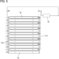
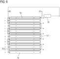
- FIG. 5 and 6 Each shows a schematic representation of a plurality of slats 1 with conductors alternately charged with a voltage potential.
- the slats 1 are numbered from top to bottom. All slats 1 have a conductor 5.0 or 5.1 charged with a voltage, with the voltage value alternating from slat 1 to slat 1, so that a voltage potential difference or voltage difference exists between adjacent conductors 1. This creates an electric field between adjacent slats 1, which covers the intermediate openings and prevents insects from flying through.
- a voltage source 10 is provided to generate the different voltages or the voltage difference.
- the voltage can be applied, for example, in a constant, pulsed, or cyclically increasing/decreasing manner, so that the electric field is also generated in a constant, pulsed, or continuously increasing/decreasing manner.
- the odd-numbered laminations 1a have a common conductor 5.1, which is supplied with a positive voltage, for example, 10 kV, by means of the voltage source 10.
- the conductor 5.1 is insulated because it is supplied with a voltage other than zero.
- the conductor 5.1 is designed as an insulated high-voltage cable.
- the routing of the conductor 5.1 along the slats 1a corresponds to the Figure 1
- the conductor 5.1 skips the straight slats 1b.
- the conductor 5.1 is guided into the lateral guide rail, where it is guided between the odd slats 1a (not shown here).
- the straight lamellae 1b are made of a metallic material and are connected via the guide pins (not shown here) to a conductor 5.0, which is grounded, i.e., has a voltage potential of zero. According to the invention, insulation is not necessary here.
Landscapes
- Engineering & Computer Science (AREA)
- Structural Engineering (AREA)
- Architecture (AREA)
- Civil Engineering (AREA)
- Life Sciences & Earth Sciences (AREA)
- Insects & Arthropods (AREA)
- Pest Control & Pesticides (AREA)
- Blinds (AREA)
- Operating, Guiding And Securing Of Roll- Type Closing Members (AREA)
- Catching Or Destruction (AREA)
Applications Claiming Priority (1)
| Application Number | Priority Date | Filing Date | Title |
|---|---|---|---|
| DE102023126123.1A DE102023126123A1 (de) | 2023-09-26 | 2023-09-26 | Beschattungseinrichtung, Gebäudesteuerung/-automation und Gebäude |
Publications (4)
| Publication Number | Publication Date |
|---|---|
| EP4530431A2 true EP4530431A2 (fr) | 2025-04-02 |
| EP4530431A3 EP4530431A3 (fr) | 2025-08-06 |
| EP4530431B1 EP4530431B1 (fr) | 2026-04-29 |
| EP4530431C0 EP4530431C0 (fr) | 2026-04-29 |
Family
ID=92791704
Family Applications (1)
| Application Number | Title | Priority Date | Filing Date |
|---|---|---|---|
| EP24199954.9A Active EP4530431B1 (fr) | 2023-09-26 | 2024-09-12 | Dispositif d'ombrage |
Country Status (2)
| Country | Link |
|---|---|
| EP (1) | EP4530431B1 (fr) |
| DE (1) | DE102023126123A1 (fr) |
Citations (8)
| Publication number | Priority date | Publication date | Assignee | Title |
|---|---|---|---|---|
| JP2001136890A (ja) | 1999-11-15 | 2001-05-22 | Satoshi Fukada | アウトドア用電気蚊取り器 |
| US20100053935A1 (en) | 2008-09-02 | 2010-03-04 | Jianli Shen | Mosquito Repellent Lamp |
| USD754278S1 (en) | 2013-03-13 | 2016-04-19 | Donna Finkel | Mosquito repellant clip |
| DE102016117770A1 (de) | 2016-09-21 | 2018-03-22 | Jürgen Grimmeisen | Kabelmanagement |
| US20190261636A1 (en) | 2016-07-21 | 2019-08-29 | Sanit Technologies Llc | Mosquito repellant |
| DE202019000228U1 (de) | 2019-01-11 | 2019-10-09 | Shpi Gmbh | Universelles Gerät zu Gebäudeautomatisierungsanwendungen |
| DE102021210642A1 (de) | 2021-09-23 | 2023-03-23 | Robert Bosch Gesellschaft mit beschränkter Haftung | Verdunklungselement mit Heizelement |
| EP3697207B1 (fr) | 2017-10-20 | 2023-06-07 | Biogents Aktiengesellschaft | Barrière contre les insectes |
Family Cites Families (1)
| Publication number | Priority date | Publication date | Assignee | Title |
|---|---|---|---|---|
| DE202021004027U1 (de) * | 2021-10-26 | 2022-05-31 | Reflexa-Werke Albrecht Gmbh | Stromabführungssystem für eine Beschattungseinrichtung und Beschattungseinrichtung hierfür |
-
2023
- 2023-09-26 DE DE102023126123.1A patent/DE102023126123A1/de active Pending
-
2024
- 2024-09-12 EP EP24199954.9A patent/EP4530431B1/fr active Active
Patent Citations (8)
| Publication number | Priority date | Publication date | Assignee | Title |
|---|---|---|---|---|
| JP2001136890A (ja) | 1999-11-15 | 2001-05-22 | Satoshi Fukada | アウトドア用電気蚊取り器 |
| US20100053935A1 (en) | 2008-09-02 | 2010-03-04 | Jianli Shen | Mosquito Repellent Lamp |
| USD754278S1 (en) | 2013-03-13 | 2016-04-19 | Donna Finkel | Mosquito repellant clip |
| US20190261636A1 (en) | 2016-07-21 | 2019-08-29 | Sanit Technologies Llc | Mosquito repellant |
| DE102016117770A1 (de) | 2016-09-21 | 2018-03-22 | Jürgen Grimmeisen | Kabelmanagement |
| EP3697207B1 (fr) | 2017-10-20 | 2023-06-07 | Biogents Aktiengesellschaft | Barrière contre les insectes |
| DE202019000228U1 (de) | 2019-01-11 | 2019-10-09 | Shpi Gmbh | Universelles Gerät zu Gebäudeautomatisierungsanwendungen |
| DE102021210642A1 (de) | 2021-09-23 | 2023-03-23 | Robert Bosch Gesellschaft mit beschränkter Haftung | Verdunklungselement mit Heizelement |
Also Published As
| Publication number | Publication date |
|---|---|
| EP4530431B1 (fr) | 2026-04-29 |
| DE102023126123A1 (de) | 2025-03-27 |
| EP4530431C0 (fr) | 2026-04-29 |
| EP4530431A3 (fr) | 2025-08-06 |
Similar Documents
| Publication | Publication Date | Title |
|---|---|---|
| DE69722889T2 (de) | Wasserdichte schirmvorrichtung von begehbarer art | |
| EP2181231B1 (fr) | Dispositif de déclenchement de fonctions dans un véhicule | |
| EP3697207B1 (fr) | Barrière contre les insectes | |
| EP4030031A1 (fr) | Dispositif de blindage | |
| EP4530431B1 (fr) | Dispositif d'ombrage | |
| DE3126930C2 (fr) | ||
| EP1698748B1 (fr) | Support pour clôture en treillis | |
| EP0606922B1 (fr) | Mecanisme de verrouillage pour portes et portails | |
| DE102013020372B4 (de) | Insektenschutz für angekipptes Fenster in senkrechter sowie waagerechter Stellung | |
| EP0032207A1 (fr) | Aération réglable à coulisse | |
| EP0639688A2 (fr) | Rideau pour des surfaces triangulaires ou autres surfaces polygonales | |
| DE202023102671U1 (de) | Automatisch schließende Insektenschutzgitter-Schiebetüre | |
| EP3430893A1 (fr) | Dispositif et agencement d'empêchement du passage des animaux | |
| EP2088277B1 (fr) | Agencement d'étanchéité pour une porte sans seuil | |
| DE19848944C1 (de) | Rolladenpanzer | |
| DE102005008645A1 (de) | Eckverbinder zum Verbinden zweier Profilleisten | |
| DE202019101126U1 (de) | Wespenschutz | |
| DE60012674T2 (de) | Abwehrvorrichtung für Vögel, wie zum Beispiel Tauben, auf einer Fläche | |
| DE3714981C1 (en) | Sealing device for a roller-blind casing | |
| DE202013104496U1 (de) | Verspannte Jalousie und Fenster oder Tür mit verspannter Jalousie | |
| EP0805252A2 (fr) | Lève-vitre à câble à course agrandie | |
| DE10233730A1 (de) | Vorrichtung zum Abwehren von Schnecken von Pflanzungen | |
| AT402429B (de) | Vorrichtung zum abdecken von öffnungen | |
| EP2009218B1 (fr) | Dispositif destiné à fermer des ouvertures d'immeubles | |
| EP4342340A1 (fr) | Rideau à lamelles |
Legal Events
| Date | Code | Title | Description |
|---|---|---|---|
| PUAI | Public reference made under article 153(3) epc to a published international application that has entered the european phase |
Free format text: ORIGINAL CODE: 0009012 |
|
| STAA | Information on the status of an ep patent application or granted ep patent |
Free format text: STATUS: THE APPLICATION HAS BEEN PUBLISHED |
|
| AK | Designated contracting states |
Kind code of ref document: A2 Designated state(s): AL AT BE BG CH CY CZ DE DK EE ES FI FR GB GR HR HU IE IS IT LI LT LU LV MC ME MK MT NL NO PL PT RO RS SE SI SK SM TR |
|
| RIC1 | Information provided on ipc code assigned before grant |
Ipc: E06B 9/322 20060101ALI20250408BHEP Ipc: E06B 9/52 20060101ALI20250408BHEP Ipc: E06B 9/30 20060101AFI20250408BHEP |
|
| PUAL | Search report despatched |
Free format text: ORIGINAL CODE: 0009013 |
|
| AK | Designated contracting states |
Kind code of ref document: A3 Designated state(s): AL AT BE BG CH CY CZ DE DK EE ES FI FR GB GR HR HU IE IS IT LI LT LU LV MC ME MK MT NL NO PL PT RO RS SE SI SK SM TR |
|
| RIC1 | Information provided on ipc code assigned before grant |
Ipc: E06B 9/30 20060101AFI20250701BHEP Ipc: E06B 9/52 20060101ALI20250701BHEP Ipc: E06B 9/322 20060101ALI20250701BHEP |
|
| STAA | Information on the status of an ep patent application or granted ep patent |
Free format text: STATUS: REQUEST FOR EXAMINATION WAS MADE |
|
| 17P | Request for examination filed |
Effective date: 20250825 |
|
| RIC1 | Information provided on ipc code assigned before grant |
Ipc: E06B 9/30 20060101AFI20251217BHEP Ipc: E06B 9/52 20060101ALI20251217BHEP Ipc: E06B 9/322 20060101ALI20251217BHEP Ipc: E06B 9/386 20060101ALI20251217BHEP |
|
| GRAP | Despatch of communication of intention to grant a patent |
Free format text: ORIGINAL CODE: EPIDOSNIGR1 |
|
| STAA | Information on the status of an ep patent application or granted ep patent |
Free format text: STATUS: GRANT OF PATENT IS INTENDED |
|
| INTG | Intention to grant announced |
Effective date: 20260209 |
|
| GRAS | Grant fee paid |
Free format text: ORIGINAL CODE: EPIDOSNIGR3 |
|
| GRAA | (expected) grant |
Free format text: ORIGINAL CODE: 0009210 |
|
| STAA | Information on the status of an ep patent application or granted ep patent |
Free format text: STATUS: THE PATENT HAS BEEN GRANTED |
|
| AK | Designated contracting states |
Kind code of ref document: B1 Designated state(s): AL AT BE BG CH CY CZ DE DK EE ES FI FR GB GR HR HU IE IS IT LI LT LU LV MC ME MK MT NL NO PL PT RO RS SE SI SK SM TR |
|
| REG | Reference to a national code |
Ref country code: CH Ref legal event code: F10 Free format text: ST27 STATUS EVENT CODE: U-0-0-F10-F00 (AS PROVIDED BY THE NATIONAL OFFICE) Effective date: 20260429 Ref country code: GB Ref legal event code: FG4D Free format text: NOT ENGLISH |
|
| REG | Reference to a national code |
Ref country code: DE Ref legal event code: R096 Ref document number: 502024001134 Country of ref document: DE |
|
| REG | Reference to a national code |
Ref country code: IE Ref legal event code: FG4D Free format text: LANGUAGE OF EP DOCUMENT: GERMAN |
|
| U01 | Request for unitary effect filed |
Effective date: 20260507 |
|
| U07 | Unitary effect registered |
Designated state(s): AT BE BG DE DK EE FI FR IT LT LU LV MT NL PT RO SE SI Effective date: 20260515 |
|
| U20 | Renewal fee for the european patent with unitary effect paid |
Year of fee payment: 3 Effective date: 20260702 |