EP4530504A1 - Système d'étanchéité pour arbre rotatif à forces d'étanchéité radiales - Google Patents
Système d'étanchéité pour arbre rotatif à forces d'étanchéité radiales Download PDFInfo
- Publication number
- EP4530504A1 EP4530504A1 EP24203018.7A EP24203018A EP4530504A1 EP 4530504 A1 EP4530504 A1 EP 4530504A1 EP 24203018 A EP24203018 A EP 24203018A EP 4530504 A1 EP4530504 A1 EP 4530504A1
- Authority
- EP
- European Patent Office
- Prior art keywords
- rotary shaft
- shaft
- seal
- stuffing box
- sleeve
- Prior art date
- Legal status (The legal status is an assumption and is not a legal conclusion. Google has not performed a legal analysis and makes no representation as to the accuracy of the status listed.)
- Pending
Links
Images

Classifications
-
- F—MECHANICAL ENGINEERING; LIGHTING; HEATING; WEAPONS; BLASTING
- F16—ENGINEERING ELEMENTS AND UNITS; GENERAL MEASURES FOR PRODUCING AND MAINTAINING EFFECTIVE FUNCTIONING OF MACHINES OR INSTALLATIONS; THERMAL INSULATION IN GENERAL
- F16J—PISTONS; CYLINDERS; SEALINGS
- F16J15/00—Sealings
- F16J15/46—Sealings with packing ring expanded or pressed into place by fluid pressure, e.g. inflatable packings
-
- F—MECHANICAL ENGINEERING; LIGHTING; HEATING; WEAPONS; BLASTING
- F16—ENGINEERING ELEMENTS AND UNITS; GENERAL MEASURES FOR PRODUCING AND MAINTAINING EFFECTIVE FUNCTIONING OF MACHINES OR INSTALLATIONS; THERMAL INSULATION IN GENERAL
- F16J—PISTONS; CYLINDERS; SEALINGS
- F16J15/00—Sealings
- F16J15/16—Sealings between relatively-moving surfaces
- F16J15/18—Sealings between relatively-moving surfaces with stuffing-boxes for elastic or plastic packings
-
- F—MECHANICAL ENGINEERING; LIGHTING; HEATING; WEAPONS; BLASTING
- F16—ENGINEERING ELEMENTS AND UNITS; GENERAL MEASURES FOR PRODUCING AND MAINTAINING EFFECTIVE FUNCTIONING OF MACHINES OR INSTALLATIONS; THERMAL INSULATION IN GENERAL
- F16J—PISTONS; CYLINDERS; SEALINGS
- F16J15/00—Sealings
- F16J15/16—Sealings between relatively-moving surfaces
- F16J15/32—Sealings between relatively-moving surfaces with elastic sealings, e.g. O-rings
- F16J15/3248—Sealings between relatively-moving surfaces with elastic sealings, e.g. O-rings provided with casings or supports
- F16J15/3252—Sealings between relatively-moving surfaces with elastic sealings, e.g. O-rings provided with casings or supports with rigid casings or supports
-
- F—MECHANICAL ENGINEERING; LIGHTING; HEATING; WEAPONS; BLASTING
- F16—ENGINEERING ELEMENTS AND UNITS; GENERAL MEASURES FOR PRODUCING AND MAINTAINING EFFECTIVE FUNCTIONING OF MACHINES OR INSTALLATIONS; THERMAL INSULATION IN GENERAL
- F16J—PISTONS; CYLINDERS; SEALINGS
- F16J15/00—Sealings
- F16J15/16—Sealings between relatively-moving surfaces
- F16J15/32—Sealings between relatively-moving surfaces with elastic sealings, e.g. O-rings
- F16J15/3284—Sealings between relatively-moving surfaces with elastic sealings, e.g. O-rings characterised by their structure; Selection of materials
Definitions
- the present invention relates to seals for a rotating shaft.
- a typical seal for a rotary shaft has a sleeve is attached to the shaft that rotates with the shaft. Surrounding the shaft is a stationary housing. Several O-rings are provided that prevent seepage of the working fluid though then arrow gap between the shaft and the sleeve, and between the seal and the container.
- the stuffing box In some rotary shaft seals, between the shaft and the housing is an annular space known as the "stuffing box".
- the stuffing box is filled with a lubricating sealant material, hereinafter referred as the "sealant".
- a pair of separated sealing rings bound the stuffing box to prevent escape of the sealant from the stuffing box, and to prevent seepage of the working fluid into the stuffing box.
- the sealant may be injected into the stuffing box by means of an injector. It is desirable to maintain the sealant at an elevated pressure in order to enhance the sealing and lubricating effects of the sealant.
- US Patent Publication 2023/0175592A1 discloses a rotary shaft seal in which the pressure on the sealant is transferred to each of the sealing rings in a direction that is parallel to the rotational axis of the shaft. A similar arrangement in which the pressure on the sealant is transferred to the sealing rings in a direction parallel to the rotational axis of the shaft, is also described in US Patent Publication 20210246983
- the present invention provides a seal for a rotary shaft.
- the seal is configured to surround a segment of a rotary shaft that extends beyond a first side of the seal into a working fluid.
- the shaft is attached to a motor generating rotation of the shaft.
- the seal serves to prevent or minimize escape of the working fluid from its container during rotation of the shaft.
- the seal has a sleeve surrounding the shaft that rotates with the shaft.
- the sleeve is surrounded by a stationary housing.
- a lubricating sealant material herein referred to as the "sealant” , fills a stuffing box between the sleeve and the housing.
- a pair of sealing rings prevent or minimize loss of the lubricant material from the annular space.
- An injection tube is filed with sealant material that is maintained under pressure.
- the pressure of the sealant is transferred to the sealant in the stuffing box, which, in turn, is transferred to the sealing rings in a radially inward direction.
- the inventors have found that by applying radially inward pressure on the sealing rings, as opposed to parallel to the rotational axis of the shaft, can improve the quality of the seal provided by the sealing rings, and allows for a more compact structure in the longitudinal direction..
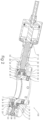
- Fig. 1 shows a seal for a rotating shaft in accordance with one embodiment of the invention.
- Fig 1 shows a rotary shaft seal 100 in a longitudinal section in accordance with one embodiment of the invention.
- the seal 100 is configured to surround a segment of a rotary shaft 3 . Referring to the orientation of the rotary shaft seal 100 in Fig. 1 , the rotary shaft 3 extends below the seal 100 into a working fluid (not shown in Fig. 1 ) that the rotary shaft 3 works on. Above the seal 100 , the shaft 3 is attached to a motor (not shown in Fig. 1 ) generating rotation of the shaft 3 .
- the seal 100 serves to prevent. or minimize passage of the working fluid from escaping the its container..
- the seal 100 comprises a sleeve 1 that surrounds the rotary shaft 3 and is attached to the shaft 3 so as to rotate with the shaft 3 .
- the sleeve 1 is surrounded by a stationary housing 22 .
- the housing 22 is immobilized by attachment to a surface 25 of the working fluid container.
- a sealing ring (also known as an "O-ring”) 7 prevents or minimizes passage of the working fluid through a thin gap between the shaft 3 and the sleeve 1 .
- a sealing ring (O-ring) 2 prevents or minimizes passage of the working fluid through a thin gap between the housing 22 and the surface 25 of the working fluid container.
- the sealing rings 2 and 7 may be made, for example, from FKM, NBR, or FFKM. Fibrous O-rings of braided sealing can also be used.
- a sealant and lubricating material fills a stuffing box 15 , between the sleeve 1 and the housing 22 .
- the sealant material in the stuffing box is maintained stationary and is prevented from rotating with the shaft 1 by means of one or more screws or pins 28 inserted into the housing 22 and terminating inside the sealant material in the space 15 .
- An example of a suitable sealant material is U-PAK ® manufactured by UTEX Industries .
- Sealing rings 8 and 9 form a pair of separated seals between the stationary housing 22 and the rotating sleeve 1 and prevent or minimize seepage of the working material in a narrow gap 24 between the housing 22 and the sleeve. 1 .
- An injection tube 26 located in the housing 22 is configured to be attached to a source of pressure.
- the injection tube 26 may be configured to be attached, for example, to an injector
- the injection tube is filed with sealant material 16 .
- the sealant material 16 in the injection tube 26 is maintained under pressure by means of the injector.
- the pressure of the sealant material 16 is transferred to the sealant in the stuffing box 15 .
- the pressure on the sealant in the stuffing box 15 by the pressurized material 16 in the injection tube 26 is transferred through two annular projections 18 and 20 in the in the stuffing box 15 , which in turn apply pressure to the sealing rings 8 and 9 , respectively. In this way, pressure is applied to the sealing rings 8 and 9 in an radially inward direction..
- the inventors have found that by applying radially inward pressure on the sealing rings 8 and 9 improves the quality of the seal by the sealing rings 8 and 9 .
- the sealing rings 8 and 9 may be immobilized by one more screws (not shown) that are fixed in the housing 22 and that extend into the sealing rings 8 and 9 .
- the sealing rings 8 and 9 may be immobilized by means of barbs (not shown) extending from the housing 22 into the sealing rings 8 and 9 .
- the inventors have found that the use of stationary rings 8 and 9 , instead of rings that are integral with the sleeve and that rotate with the sleeve generates pressure on the sealing rings, an effect referred to as mechanical packing or compression packing, which improves the sealing effect of the sealing rings 8 and 9 .
- the rotary shaft seal 100 may be provided with an air injection system (not shown) that allows air to be injected into the sealing gap 24 .
- an air injection system (not shown) that allows air to be injected into the sealing gap 24 .
- the inventors have found that injecting air into the gap adsorbs and dilutes any gaseous debris in the working fluid that may be generated during rotation of the shaft.
- injecting water into the gap 24 can remove particulate debris that forms in the gap 24 during rotation of the shaft.
Landscapes
- Engineering & Computer Science (AREA)
- General Engineering & Computer Science (AREA)
- Mechanical Engineering (AREA)
- Physics & Mathematics (AREA)
- Architecture (AREA)
- Fluid Mechanics (AREA)
- Sealing Devices (AREA)
- Sealing Using Fluids, Sealing Without Contact, And Removal Of Oil (AREA)
Applications Claiming Priority (1)
| Application Number | Priority Date | Filing Date | Title |
|---|---|---|---|
| US202363540705P | 2023-09-27 | 2023-09-27 |
Publications (1)
| Publication Number | Publication Date |
|---|---|
| EP4530504A1 true EP4530504A1 (fr) | 2025-04-02 |
Family
ID=92926105
Family Applications (1)
| Application Number | Title | Priority Date | Filing Date |
|---|---|---|---|
| EP24203018.7A Pending EP4530504A1 (fr) | 2023-09-27 | 2024-09-26 | Système d'étanchéité pour arbre rotatif à forces d'étanchéité radiales |
Country Status (2)
| Country | Link |
|---|---|
| US (1) | US20250102064A1 (fr) |
| EP (1) | EP4530504A1 (fr) |
Citations (4)
| Publication number | Priority date | Publication date | Assignee | Title |
|---|---|---|---|---|
| JPS6375394A (ja) * | 1986-09-19 | 1988-04-05 | Hitachi Ltd | ポンプの軸封装置 |
| US7931125B2 (en) * | 2001-05-16 | 2011-04-26 | Freudenberg-Nok General Partnership | Shaft seal with lubrication device |
| US20210246983A1 (en) | 2020-02-06 | 2021-08-12 | Tamar (R.C.) Technologies Development Ltd. | Sealing system for rotary shaft |
| US20230175592A1 (en) | 2021-12-08 | 2023-06-08 | Tamar (R.C.) Technologies Development Ltd. | Sealing system for rotary shaft |
Family Cites Families (8)
| Publication number | Priority date | Publication date | Assignee | Title |
|---|---|---|---|---|
| US4384726A (en) * | 1981-11-02 | 1983-05-24 | Acf Industries, Incorporated | Expandable lubricating packing assembly for wellheads |
| US4709758A (en) * | 1985-12-06 | 1987-12-01 | Baker Oil Tools, Inc. | High temperature packer for well conduits |
| JPH0636364Y2 (ja) * | 1989-12-26 | 1994-09-21 | イーグル工業株式会社 | スラリーシールのクエンチング機構 |
| CH684170A5 (de) * | 1991-01-16 | 1994-07-29 | Gericke Ag | Vorrichtung zur Lagerung und Abdichtung von Wellen in einem Mischer. |
| US5792525A (en) * | 1995-03-31 | 1998-08-11 | W. L. Gore & Associates, Inc. | Creep resistant shaped article of densified expanded polytetrafluoroethylene |
| DE10342751B4 (de) * | 2003-09-16 | 2005-08-18 | Samson Ag | Dichtungsanordnung |
| IL174005A0 (en) * | 2006-02-28 | 2008-01-20 | Tamar R C Technologies Dev Ltd | Apparatus for delivering sealant to a stuffing box of a rotary shaft |
| US20090194949A1 (en) * | 2008-02-04 | 2009-08-06 | Tamar Technological Development Ltd. | Shaft for viscous sealant systems |
-
2024
- 2024-09-26 EP EP24203018.7A patent/EP4530504A1/fr active Pending
- 2024-09-27 US US18/899,339 patent/US20250102064A1/en active Pending
Patent Citations (4)
| Publication number | Priority date | Publication date | Assignee | Title |
|---|---|---|---|---|
| JPS6375394A (ja) * | 1986-09-19 | 1988-04-05 | Hitachi Ltd | ポンプの軸封装置 |
| US7931125B2 (en) * | 2001-05-16 | 2011-04-26 | Freudenberg-Nok General Partnership | Shaft seal with lubrication device |
| US20210246983A1 (en) | 2020-02-06 | 2021-08-12 | Tamar (R.C.) Technologies Development Ltd. | Sealing system for rotary shaft |
| US20230175592A1 (en) | 2021-12-08 | 2023-06-08 | Tamar (R.C.) Technologies Development Ltd. | Sealing system for rotary shaft |
Also Published As
| Publication number | Publication date |
|---|---|
| US20250102064A1 (en) | 2025-03-27 |
Similar Documents
| Publication | Publication Date | Title |
|---|---|---|
| US8356819B2 (en) | Low and reverse pressure application hydrodynamic pressurizing seals | |
| KR940007405A (ko) | 시일 배열 나선홈 시일 시스템 및 가공 유체의 누출에 대해 시일링하는 방법 | |
| KR950700491A (ko) | 회전 라이너를 구비하는 액체 링펌프(liquid ring pumps with rotating liners) | |
| EP0243406A1 (fr) | Procede d'etancheite pour assemblages de paliers. | |
| CA2436924A1 (fr) | Boite a garniture pour entrainement de pompe a rotor helicoidal excentre | |
| WO2022055830A1 (fr) | Fouloir réglable à distance pour système d'étanchéité d'arbre | |
| EP4530504A1 (fr) | Système d'étanchéité pour arbre rotatif à forces d'étanchéité radiales | |
| AU2009232214A1 (en) | Internally pressurised seals | |
| KR20160029521A (ko) | 머드 펌프 | |
| KR101370773B1 (ko) | 메카니컬 씰 | |
| US20230175592A1 (en) | Sealing system for rotary shaft | |
| US3117794A (en) | Shaft glands | |
| JP3008013B2 (ja) | 流体機器用軸封装置 | |
| JP4009585B2 (ja) | 軸封装置 | |
| JPH08159289A (ja) | 軸封装置 | |
| CA2288230A1 (fr) | Cartouche a joints a levre multiples et manchon ajustable | |
| CN105927739B (zh) | 一种燃油泵用密封装置 | |
| US3198530A (en) | Outside balanced mechanical seal | |
| US1487567A (en) | Packing means for rotary pumps | |
| JP2003222246A (ja) | 軸封装置用のストップリング | |
| US20210033192A1 (en) | Axially preloaded packing ring sets | |
| US2852284A (en) | Liquid seal for rotating shafts | |
| US1956844A (en) | Fluxion seal ring | |
| US20240102471A1 (en) | Universal pump bracket | |
| EP4579106A1 (fr) | Structure d'étanchéité de palier |
Legal Events
| Date | Code | Title | Description |
|---|---|---|---|
| PUAI | Public reference made under article 153(3) epc to a published international application that has entered the european phase |
Free format text: ORIGINAL CODE: 0009012 |
|
| STAA | Information on the status of an ep patent application or granted ep patent |
Free format text: STATUS: THE APPLICATION HAS BEEN PUBLISHED |
|
| AK | Designated contracting states |
Kind code of ref document: A1 Designated state(s): AL AT BE BG CH CY CZ DE DK EE ES FI FR GB GR HR HU IE IS IT LI LT LU LV MC ME MK MT NL NO PL PT RO RS SE SI SK SM TR |
|
| STAA | Information on the status of an ep patent application or granted ep patent |
Free format text: STATUS: REQUEST FOR EXAMINATION WAS MADE |
|
| 17P | Request for examination filed |
Effective date: 20250926 |