EP4530515A2 - Sanitärverbinder - Google Patents
Sanitärverbinder Download PDFInfo
- Publication number
- EP4530515A2 EP4530515A2 EP25157364.8A EP25157364A EP4530515A2 EP 4530515 A2 EP4530515 A2 EP 4530515A2 EP 25157364 A EP25157364 A EP 25157364A EP 4530515 A2 EP4530515 A2 EP 4530515A2
- Authority
- EP
- European Patent Office
- Prior art keywords
- collet
- pipe
- connector
- locking cap
- connector according
- Prior art date
- Legal status (The legal status is an assumption and is not a legal conclusion. Google has not performed a legal analysis and makes no representation as to the accuracy of the status listed.)
- Pending
Links
Images








Classifications
-
- F—MECHANICAL ENGINEERING; LIGHTING; HEATING; WEAPONS; BLASTING
- F16—ENGINEERING ELEMENTS AND UNITS; GENERAL MEASURES FOR PRODUCING AND MAINTAINING EFFECTIVE FUNCTIONING OF MACHINES OR INSTALLATIONS; THERMAL INSULATION IN GENERAL
- F16L—PIPES; JOINTS OR FITTINGS FOR PIPES; SUPPORTS FOR PIPES, CABLES OR PROTECTIVE TUBING; MEANS FOR THERMAL INSULATION IN GENERAL
- F16L47/00—Connecting arrangements or other fittings specially adapted to be made of plastics or to be used with pipes made of plastics
- F16L47/04—Connecting arrangements or other fittings specially adapted to be made of plastics or to be used with pipes made of plastics with a swivel nut or collar engaging the pipe
-
- F—MECHANICAL ENGINEERING; LIGHTING; HEATING; WEAPONS; BLASTING
- F16—ENGINEERING ELEMENTS AND UNITS; GENERAL MEASURES FOR PRODUCING AND MAINTAINING EFFECTIVE FUNCTIONING OF MACHINES OR INSTALLATIONS; THERMAL INSULATION IN GENERAL
- F16L—PIPES; JOINTS OR FITTINGS FOR PIPES; SUPPORTS FOR PIPES, CABLES OR PROTECTIVE TUBING; MEANS FOR THERMAL INSULATION IN GENERAL
- F16L33/00—Arrangements for connecting hoses to rigid members; Rigid hose-connectors, i.e. single members engaging both hoses
- F16L33/22—Arrangements for connecting hoses to rigid members; Rigid hose-connectors, i.e. single members engaging both hoses with means not mentioned in the preceding groups for gripping the hose between inner and outer parts
- F16L33/223—Arrangements for connecting hoses to rigid members; Rigid hose-connectors, i.e. single members engaging both hoses with means not mentioned in the preceding groups for gripping the hose between inner and outer parts the sealing surfaces being pressed together by means of a member, e.g. a swivel nut, screwed on or into one of the joint parts
-
- F—MECHANICAL ENGINEERING; LIGHTING; HEATING; WEAPONS; BLASTING
- F16—ENGINEERING ELEMENTS AND UNITS; GENERAL MEASURES FOR PRODUCING AND MAINTAINING EFFECTIVE FUNCTIONING OF MACHINES OR INSTALLATIONS; THERMAL INSULATION IN GENERAL
- F16L—PIPES; JOINTS OR FITTINGS FOR PIPES; SUPPORTS FOR PIPES, CABLES OR PROTECTIVE TUBING; MEANS FOR THERMAL INSULATION IN GENERAL
- F16L33/00—Arrangements for connecting hoses to rigid members; Rigid hose-connectors, i.e. single members engaging both hoses
- F16L33/22—Arrangements for connecting hoses to rigid members; Rigid hose-connectors, i.e. single members engaging both hoses with means not mentioned in the preceding groups for gripping the hose between inner and outer parts
-
- F—MECHANICAL ENGINEERING; LIGHTING; HEATING; WEAPONS; BLASTING
- F16—ENGINEERING ELEMENTS AND UNITS; GENERAL MEASURES FOR PRODUCING AND MAINTAINING EFFECTIVE FUNCTIONING OF MACHINES OR INSTALLATIONS; THERMAL INSULATION IN GENERAL
- F16L—PIPES; JOINTS OR FITTINGS FOR PIPES; SUPPORTS FOR PIPES, CABLES OR PROTECTIVE TUBING; MEANS FOR THERMAL INSULATION IN GENERAL
- F16L19/00—Joints in which sealing surfaces are pressed together by means of a member, e.g. a swivel nut, screwed on, or into, one of the joint parts
- F16L19/02—Pipe ends provided with collars or flanges, integral with the pipe or not, pressed together by a screwed member
- F16L19/0206—Pipe ends provided with collars or flanges, integral with the pipe or not, pressed together by a screwed member the collar not being integral with the pipe
-
- F—MECHANICAL ENGINEERING; LIGHTING; HEATING; WEAPONS; BLASTING
- F16—ENGINEERING ELEMENTS AND UNITS; GENERAL MEASURES FOR PRODUCING AND MAINTAINING EFFECTIVE FUNCTIONING OF MACHINES OR INSTALLATIONS; THERMAL INSULATION IN GENERAL
- F16L—PIPES; JOINTS OR FITTINGS FOR PIPES; SUPPORTS FOR PIPES, CABLES OR PROTECTIVE TUBING; MEANS FOR THERMAL INSULATION IN GENERAL
- F16L19/00—Joints in which sealing surfaces are pressed together by means of a member, e.g. a swivel nut, screwed on, or into, one of the joint parts
- F16L19/02—Pipe ends provided with collars or flanges, integral with the pipe or not, pressed together by a screwed member
- F16L19/0237—Pipe ends provided with collars or flanges, integral with the pipe or not, pressed together by a screwed member specially adapted for use with attachments, e.g. reduction units, T-pieces, bends or the like
-
- F—MECHANICAL ENGINEERING; LIGHTING; HEATING; WEAPONS; BLASTING
- F16—ENGINEERING ELEMENTS AND UNITS; GENERAL MEASURES FOR PRODUCING AND MAINTAINING EFFECTIVE FUNCTIONING OF MACHINES OR INSTALLATIONS; THERMAL INSULATION IN GENERAL
- F16L—PIPES; JOINTS OR FITTINGS FOR PIPES; SUPPORTS FOR PIPES, CABLES OR PROTECTIVE TUBING; MEANS FOR THERMAL INSULATION IN GENERAL
- F16L19/00—Joints in which sealing surfaces are pressed together by means of a member, e.g. a swivel nut, screwed on, or into, one of the joint parts
- F16L19/06—Joints in which sealing surfaces are pressed together by means of a member, e.g. a swivel nut, screwed on, or into, one of the joint parts in which radial clamping is obtained by wedging action on non-deformed pipe ends
- F16L19/065—Joints in which sealing surfaces are pressed together by means of a member, e.g. a swivel nut, screwed on, or into, one of the joint parts in which radial clamping is obtained by wedging action on non-deformed pipe ends the wedging action being effected by means of a ring
-
- F—MECHANICAL ENGINEERING; LIGHTING; HEATING; WEAPONS; BLASTING
- F16—ENGINEERING ELEMENTS AND UNITS; GENERAL MEASURES FOR PRODUCING AND MAINTAINING EFFECTIVE FUNCTIONING OF MACHINES OR INSTALLATIONS; THERMAL INSULATION IN GENERAL
- F16L—PIPES; JOINTS OR FITTINGS FOR PIPES; SUPPORTS FOR PIPES, CABLES OR PROTECTIVE TUBING; MEANS FOR THERMAL INSULATION IN GENERAL
- F16L19/00—Joints in which sealing surfaces are pressed together by means of a member, e.g. a swivel nut, screwed on, or into, one of the joint parts
- F16L19/08—Joints in which sealing surfaces are pressed together by means of a member, e.g. a swivel nut, screwed on, or into, one of the joint parts with metal rings which bite into the wall of the pipe
-
- F—MECHANICAL ENGINEERING; LIGHTING; HEATING; WEAPONS; BLASTING
- F16—ENGINEERING ELEMENTS AND UNITS; GENERAL MEASURES FOR PRODUCING AND MAINTAINING EFFECTIVE FUNCTIONING OF MACHINES OR INSTALLATIONS; THERMAL INSULATION IN GENERAL
- F16L—PIPES; JOINTS OR FITTINGS FOR PIPES; SUPPORTS FOR PIPES, CABLES OR PROTECTIVE TUBING; MEANS FOR THERMAL INSULATION IN GENERAL
- F16L33/00—Arrangements for connecting hoses to rigid members; Rigid hose-connectors, i.e. single members engaging both hoses
- F16L33/22—Arrangements for connecting hoses to rigid members; Rigid hose-connectors, i.e. single members engaging both hoses with means not mentioned in the preceding groups for gripping the hose between inner and outer parts
- F16L33/223—Arrangements for connecting hoses to rigid members; Rigid hose-connectors, i.e. single members engaging both hoses with means not mentioned in the preceding groups for gripping the hose between inner and outer parts the sealing surfaces being pressed together by means of a member, e.g. a swivel nut, screwed on or into one of the joint parts
- F16L33/224—Arrangements for connecting hoses to rigid members; Rigid hose-connectors, i.e. single members engaging both hoses with means not mentioned in the preceding groups for gripping the hose between inner and outer parts the sealing surfaces being pressed together by means of a member, e.g. a swivel nut, screwed on or into one of the joint parts a clamping ring being arranged between the threaded member and the connecting member
-
- F—MECHANICAL ENGINEERING; LIGHTING; HEATING; WEAPONS; BLASTING
- F16—ENGINEERING ELEMENTS AND UNITS; GENERAL MEASURES FOR PRODUCING AND MAINTAINING EFFECTIVE FUNCTIONING OF MACHINES OR INSTALLATIONS; THERMAL INSULATION IN GENERAL
- F16L—PIPES; JOINTS OR FITTINGS FOR PIPES; SUPPORTS FOR PIPES, CABLES OR PROTECTIVE TUBING; MEANS FOR THERMAL INSULATION IN GENERAL
- F16L2201/00—Special arrangements for pipe couplings
- F16L2201/10—Indicators for correct coupling
-
- F—MECHANICAL ENGINEERING; LIGHTING; HEATING; WEAPONS; BLASTING
- F16—ENGINEERING ELEMENTS AND UNITS; GENERAL MEASURES FOR PRODUCING AND MAINTAINING EFFECTIVE FUNCTIONING OF MACHINES OR INSTALLATIONS; THERMAL INSULATION IN GENERAL
- F16L—PIPES; JOINTS OR FITTINGS FOR PIPES; SUPPORTS FOR PIPES, CABLES OR PROTECTIVE TUBING; MEANS FOR THERMAL INSULATION IN GENERAL
- F16L2201/00—Special arrangements for pipe couplings
- F16L2201/30—Detecting leaks
Definitions
- the present disclosure relates to a plumbing connector for use with plastic pipe. More specifically, it relates to a connector suitable for use with multi layered pipe (MLCP) for heating and hot/cold water systems.
- MLCP multi layered pipe
- These connectors are inside diameter (ID) connectors such that they have a body which fits inside the pipe and seals on the inner wall of the pipe. This is primarily done because these multi layered pipes have a laminated structure and the pipe may tend to delaminate in the vicinity of a cut end. This cut end would be exposed to the fluid within the pipe if the seal were made with the outer diameter of the pipe. The liquid could cause further separation of the layers and ultimately cause a failure in the vicinity of the joint. By sealing on the inner diameter of the pipe, the cut end of the pipe is on the "dry" side of the seal such that this does not occur.
- ID inside diameter
- MLCP connectors are overwhelmingly of a press-fit type.
- Such a connector has an inner sleeve over which the pipe is fitted and an outer sleeve which is plastically deformed by pressing (hence the term 'press-fit') in order to compress the body of the connector onto the pipe and, in the process, pressing the pipe onto a seal in the body.
- connectors have a visual indication to show that the crimping has taken place. This may, for example, be in the form of a plastic ring which will fall off the connector once the crimping tool has been applied. Although this provides a visual indication that the crimping tool has been applied, there is no guarantee that the crimping operation has been carried out correctly and that the joint is now sound.
- the press fit connector is designed to have a fairly low clearance in relation to the diameter of pipe with which it is intended to be used. This cuts down the amount of deformation required during the crimping operation as it would otherwise require an impractically high force and create internal stresses on the connector material if it was necessary to deform the material too much during the crimping operation. As such, a chamfer has to be cut onto the inner and outer leading edges of the pipe in order to aid its insertion into the connector. This can be relatively time consuming and, if not done properly, it can create difficulties in making the connection.
- this type of connector is not demountable. Although this may not be a problem for many applications, it limits the use of such connectors to situations where they do not need to be reused.
- the connector body has a central portion with a sealing ring which seals on the inside diameter of the pipe.
- the body contains a gripper with inner and outer portions which engage with both the inside diameter and the outside diameter of the pipe.
- the grab ring is spring-loaded to urge it towards the open end of the connector.
- the outermost part of the connector has a ramped surface which engages with a complementary ramped surface on the gripper so that any force tending to pull the pipe out of the connector would cause these ramped surfaces to engage one another thereby providing an increasing gripping force on the pipe.
- the outer part of the body is provided with a pair of windows so that the pipe is visible through the connector wall.
- WO2015/089583 shows a further push-fit connector suitable for sealing the inside diameter of a plastic or MLCP plumbing pipe. This has a grab ring to hold the pipe in place. A collet is provided, but this is simply to retain an outer sleeve. As with the above-mentioned Wavin connector, this is not demountable. A coloured ring is provided within the connector which is pushed along the connector by the insertion of a pipe and is visible through slots at the distal end of the connector.
- the windows are relatively small and therefore need to be inspected close up to determine whether the pipe is in place.
- the windows are a reasonable distance from the end of the pipe such that the window can only be used to verify that the pipe is part-way inside the connector.
- the coloured ring is also not a reliable indication of the position of the pipe within the connector as it is possible that the ring and the pipe can separate from one another. Under these circumstances, a visual indication of the position of the ring gives a false impression of the position of the end of the pipe.
- Both of the above described push-fit connectors also suffer from the problem set out above concerning the quality of the finish on the cut end of the pipe. Because they rely on components within the connector which can only move with respect to one another in response to movement of the pipe within the connector, the tolerances within the connector again need to be relatively tight so that the deflections required to grip the pipe can provide an adequate gripping force within a short amount of axial travel. Because of this, the end of the pipe must be de-burred and chamfered at both leading edges in order to be able to be inserted within the connector. Even then, the insertion force is likely to be relatively high as the insertion is resisted, to some extent, by the presence of the sealing ring.
- Press fit connectors do not scale up well given the additional force needed to deform the material of a larger connector. However, larger sizes of push fit connector are even more difficult to use due to the effort needed to push pipe through the gripper and O-ring.
- a domestic hose connector is designed to operate at ambient temperatures.
- plumbing connectors are required to connect pipes that carry hot water which is typically at a temperature of at a continuous temperature of 95°C, and above 100°C for short periods.
- WO 2011/099519 discloses a metal connector for connecting with the braided hose.
- Such braided hoses have a much higher degree of deformability than the pipes which are addressed by the present disclosure. As such, good sealing and gripping can be provided by the higher degree of deflection of the material of the hose itself. This places very different requirements on the connector to those of the present disclosure.
- a similar connector is disclosed in JP 2011/247335 .
- EP 0168260 describes a plastic connector which is again suited to a highly flexible hose. This has a large recess surrounding an outer face of the tubular body, into which the hose is deflected to a significant extent by the collet.
- the object of the present disclosure is to address one or more of the above-mentioned problems.
- a pipe connector comprising: a hollow body having a central throughway defining an axis, the body comprising a tubular part at at least one end, the tubular part having an outer face to seal, in use, with an inner diameter of a pipe placed over the tubular part:
- Such a connector provides a number of benefits over the above-mentioned prior art in the field of commercial plumbing connectors.
- the presence of the locking cap which deflects the collet onto the pipe means that a greater degree of inward deflection of the collet can be provided as opposed to the press-fit and push-fit connectors described above.
- This greater degree of deflection means that the initial opening between the body and the collet can be larger than in the prior art such that there is no need for a chamfer on the cut end of the pipe making the connection process much quicker. It can also provide a lower insertion force so that it is easier to insert the pipe into the connector.
- the presence of the locking cap which needs to be rotated to secure the joint means that this is not a 'push-fit' connector as it cannot be made up just by pushing the pipe into the connector.
- the force required to screw the locking cap into place could be made large enough that it requires the use of a tool. This would help the connector to gain acceptance in the commercial plumbing sector.
- Such a tool can be smaller and cheaper than the tools required of the above press fit connectors as it is required to perform a screwing action not a crimping action. It can therefore be a simple wrench.
- the force required to screw the locking cap into place could be made low enough so that the joint can be made up by hand.
- the present disclosure is easily scalable as larger connectors need only slightly more closing torque than smaller ones.
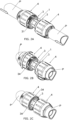
- the locking cap is in a first position relative to the collet when unlocked and a second position when locked. This provides a clear visual indication of the state of the connector which can be readily identified from a distance.
- the connector can be made as a single use connector if the locking cap is unable to be screwed back from the locked position. However, it can also readily be made demountable provided that the locking cap is able to be unscrewed.
- the present disclosure therefore provides numerous and significant benefits over all of the prior art currently available in the field of ID connectors for plumbing applications.
- the cap In terms of the art in other fields, in a domestic hose connector, the cap has to be separable from the collet and cannot be captive on it as in the present disclosure.
- the legs of the collet can easily be deflected inwardly as the hose is pushed into the body. This will prevent the connecter being properly secured and sealed. Because of this, the hose needs to be pushed into the collet without the cap in the way so that the user can see that the legs are not being deflected inwardly. If this happens they can manually manipulate the hose and/or collet to make sure that the legs are not deflected inwardly. Further if the cap were captive on the collet this would inhibit the ability of the legs to deflect outwardly which would make it difficult to insert the hose. It is therefore essential in a hose connector that the cap can be separated form the collet to use the connector.
- EP1860260 has a large groove in the hollow body and does not have teeth on the collet. The gripping is carried out by deflecting the flexible tube into a groove on the tubular part. None of these references discloses that the locking cap is captive on the collet.
- the inner diameter of a first constriction at an open end of the collet is greater than the inner diameter of the part of the collet that receives the pipe distally of the sealing ring. This allows the pipe to be more easily inserted into the collet which is wider at its open end and reduces in diameter deeper into the collet.
- the collet has two sets of teeth, the sets being axially spaced from one another.
- the inner wall of the collet bulges inwardly.
- the connector is preferably capable of maintaining the seal when exposed to a continuous temperature of 70°C, preferably 80°C and more preferably 90°C. A domestic hose connector cannot operate at these temperatures.
- the connector should preferably be able to meet ISO 21003.
- the locking cap and body preferably have an end stop to prevent them from being unscrewed beyond the unlocked configuration.
- the locking cap can then be screwed to this end stop during the assembly process and the connector is supplied to the end user in a condition in which it is ready to use.
- the collet preferably has at least one through slot at its distal end which is exposed in the locked and unlocked configurations allowing the end of the pipe to be visible, in use, through the slot when the connector is in the locked and unlocked configurations with the pipe inserted. This allows the user to verify that the end of the pipe itself has been fully inserted into the connector in both of the locked and unlocked configurations.
- a pipe connector comprising: a hollow body having a central throughway defining an axis, the body comprising a tubular part at at least one end, the tubular part having an outer face to seal, in use, with an inner diameter of a pipe placed over the tubular part:
- the movement of the locking cap onto the collet means that there is already a clear visual difference between the locked and unlocked configurations.
- the distal end of the collet protrudes from the locking cap and is visible to the user in the unlocked configuration and is covered by the locking cap or protrudes to a lesser extent in the locked configuration. This provides an enhanced visual difference in the two configurations.
- the proximal end of the collet is preferably visible at the proximal end of the connector in the locked configuration, in use, with the pipe in place.
- collet and locking cap are preferably different colours.
- This forms a third aspect of the disclosure which is pipe connector comprising: a hollow body having a central throughway defining an axis, the body comprising a tubular part at at least one end, the tubular part having an outer face to seal, in use, with an inner diameter of a pipe placed over the tubular part:
- Prior art connectors have hexagonal caps to allow the connector to be tightened with a spanner.
- the locking cap is devoid of opposing flat surfaces. This can be achieved, for example, if no part of the locking cap has a hexagonal cross section in a radial plane.
- This forms a fourth aspect of the disclosure which is pipe connector comprising: a hollow body having a central throughway defining an axis, the body comprising a tubular part at at least one end, the tubular part having an outer face to seal, in use, with an inner diameter of a pipe placed over the tubular part:
- the collet and locking cap have complementary end stops to prevent overtightening. This stops overstressing of the connector.
- collet and locking cap preferably have complementary features to produce a sound when the locking cap reaches the locked configuration. This indicates to the user that the connector is fully locked and should therefore give them confidence that the connector has been correctly deployed as well as ensuring that they do not try to overstress the connection.
- This forms a fifth aspect of the disclosure which is a pipe connector comprising: a hollow body having a central throughway defining an axis, the body comprising a tubular part at at least one end, the tubular part having an outer face to seal, in use, with an inner diameter of a pipe placed over the tubular part:
- the complementary features include a break off tab configured to be broken off as the locking cap reaches the locked configuration.
- a tab which breaks off, as opposed to one which abruptly hits against an opposing surface has been found to produce a louder noise.
- the collet and locking cap are configured to retain the broken off tab in the connector. This avoids loose pieces of plastic in the vicinity of the connector joint which might become caught up in other components and provide unwanted waste and/or a hazard which might interfere with other connectors.
- At least one, and more preferably all of the body, collet and locking cap have a tensile modulus of greater than 2000Mpa and a heat distortion temperature of greater than 200°C.
- Preferably all of the body, collet and locking cap have a tensile modulus of greater than 2000Mpa.
- the hose grip typically has a tensile modulus of 1200 and a heat distortion temperature 75°C while the inner core typically has a tensile modulus of 2700 and a heat distortion temperature of 104°C.
- the disclosure also extends to a method of connecting to a commercial plumbing pipe comprising attaching a connector according to any of the above aspects to the pipe.
- One or more of the hollow body, collet and locking cap may be made of plastic.
- the connector may be suitable for other uses, the pipe connector has been designed to be suitable for a commercial plumbing pipe.
- the plumbing connector described below shows a double-ended axial connector in which both ends are configured according to the present disclosure.
- the connector may be applied to other shapes such as a right-angled or T connector. Further, the connector may be provided at only one end and the opposite end may have a different type of connection or be integrated into some other component.
- the connector is a plumbing connector for use with a plastic pipe P.
- a plastic pipe P This may be a single layer plastic pipe, but is more commonly a multi-layered pipe (MLCP).
- MLCP multi-layered pipe
- the multi-layered pipe has a number of layers L, typically inner and outer polymeric layers and an intermediate layer of a metal such as aluminium.
- Plumbing connectors must be suitable for being used in both cold and hot water systems as well as in heating systems. As such, they must be able to cope with a continuous temperature of 95°C and must also be able to cope with temperatures of above 100°C for short periods.
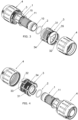
- the connector is made from just four components, namely a body 1, an O-ring 2, a collet 3 and a locking cap 4 as shown, for example, in Fig. 3 .
- the body 1 is a double-ended body such that it has an O-ring 2, collet 3 and locking cap 4 at either end.
- the components are preferably high performance polymers.
- the body 1 may be unfilled PPSU/PSU/PPS/PVDF.
- the locking cap 4 and collet 3 the may be the same materials but these may be glass filled.
- Other possibilities for the cap and collet may be GF PA66/PA12/Amodel/Grivory'
- the body 1 has a generally tubular configuration with a throughway 10 extending axially along a main central axis X ( Fig. 1B ).
- the body 1 At the proximal end (i.e. the end closest to the open end of the connector, the distal end being the opposite end furthest from the open end), the body 1 has a tubular portion 11 over which the pipe P is received as shown, for example, in Fig. 6 .
- Partway along the tubular portion 11 is an annular groove 12 which receives the O-ring 2.
- the O-ring 2 seals with the inner diameter of the pipe P as described in greater detail below.
- the tubular portion 11 Distally of the O-ring 2, the tubular portion 11 is provided with a number crenulations 13. These are provided simply as a way of reducing the mass of material required for the body 1.
- the collet 3 has a lip 30 at one end via which it is snap fitted into a groove 14 in the body 1.
- the outer face of the collet 3 is provided with a screw thread 31.
- the locking cap 4 has a complementary screw thread 40 such that the locking cap 4 can be rotated with respect to the collect to lock the connector as described in greater detail below.
- the locking cap 4 is also captive on the collet 3 as also described in greater detail below.
- the collet 3 is provided with a plurality of first axial slots 32 extending from the proximal end.
- a plurality of second axial slots 34 extend from the opposite end of the collet and these axially overlap with the first axial slots 32 but are circumferentially offset with respect to these slots.
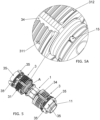
- the collet 3 is made of a relatively rigid material and the slots provides the necessary flexibility for the collet to be fitted in place. This is done by forcing the collet 3 over the tubular portion 11 (as shown in Fig. 5 ) until the lip 30 snaps in the groove 14.
- a number of detents 15 are provided at the distal end of the tubular portion 11 which engage in the ends of the second axial slots 34 to prevent rotation of the collet 3 with respect to the body 1. The collet 3 is thereby axially and radially fixed with respect to the body 1.
- the locking cap 4 is then pressed on to the collet 3.
- the first axial slots 32 allow the distal end of the collet to compress and allow the locking cap 4 to be pressed onto the collet at least until some of the part of the screw thread 31 engages with part of the screw thread 40.
- the collet may be pushed to a desired location at which the two screw threads 31, 40 begin to engage.
- the locking cap 4 is pressed onto the collet beyond the unlocked position and the locking cap 4 is then screwed back to the unlocked position shown in Fig. 1A .
- an inwardly extending annular shoulder 41 engages with a complementary outwardly extending shoulder 310 on the collet as best shown in Fig. 6A . This provides a stop to ensure that the locking cap 4 cannot be unscrewed beyond this unlocked position, thereby holding the locking cap 4 captive on the collet 3.
- the first axial slots 32 also serve to separate the distal end of the collet 3 into four separate legs 35. There could be a different number of first axial slots 32 and therefore a corresponding different number of legs 35.
- Each leg 35 has an inner tooth 36 and an outer tooth 37 closer to the proximal end of the collet than the inner tooth 36.
- Distally of the inner tooth 36 is a pipe receiving portion 38 with an inner diameter which corresponds to the outer diameter of the pipe P.
- the collet has an inward bulge 37A between the two sets of teeth.
- the inner diameter is significantly larger than the outer diameter of the pipe P. This can be seen in Fig. 6A where the innermost edge 39 of the proximal end of the collet is spaced from the pipe P.
- the connector is supplied in this unlocked configuration to an end user.
- This configuration of connector is depicted in Figs 1A , 2A , 3 , 6 , 6A and 9A .
- the collet 3 projects to a reasonably significant extent from the distal end of the cap 4.
- Fig. 1A Fig. 1C
- the proximal end of the collet is substantially flush with the proximal end of the body in the locked configuration so the user has a visual indication that the collet is in the correct position
- This visual significance can be enhanced if the collet 3 and locking cap 4 are made from materials of contrasting colours. This makes it easy to inspect the connections from a distance and to determine whether any have yet to be locked and also to confirm that they have been locked.
- the pipes P can be inserted into the connector. They are fully inserted to the position shown in Fig. 6 and Fig. 8 where the pipe P abuts against the lip 30 in the collet 3.
- the connector is specifically designed to provide a low insertion force for the pipe P.
- a number of features of the design allow for this.
- the inner diameter of the collet 3 at the proximal end is significantly larger than the pipe P as can be seen in Fig. 6A . This allows the pipe to be inserted with little or no interaction with the collet.
- the outer tooth 37 is spaced from the pipe P.
- the inner tooth 36 can be similarly spaced, but is shown in Fig. 6A with a very minimal interaction with the pipe P which may cause a very small outward deflection of the collet providing a negligible increase in insertion force.
- the tubular portion 11 of the body 1 is designed to have a reasonably close tolerance with the inner diameter of the pipe P which again may give rise to a minimal insertion force.
- the O-ring seal 2 will engage with the pipe P on insertion.
- the annular groove 12 is designed to be deeper than usual such that insertion of the pipe causes a relatively small compression of the O-ring 2 upon insertion.
- the pipe P is being inserted into a channel which is relatively wide at the opening and gently tapers towards the distal end.
- the pipe P does not require a lead-in chamfer on either leading edge in order to be inserted in the connector.
- the locking cap 4 now covers up the collet 3 to provide a visual indication of the locked position.
- the effect of screwing the locking cap 4 to the locked position is to compress the collet 3 which can best be seen in a comparison of Figs. 6 and 6A with Figs. 7 and 7A .
- the proximal end of the collet 3 is within an annular recess 42 within the body 4.
- This annular recess 42 terminates at a curved shoulder 43 which abuts against the outermost edge of the proximal end of the collet 3.
- the shoulder 43 immediately runs over the outer face of the proximal portion of the collet 3 thereby compressing the legs 35 of the collet 3 onto the pipe P.
- This inward deflection of the collet legs 35 causes the teeth 36, 37 to bite into the outer face of the pipe P.
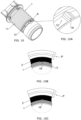
- the inward deflection also causes the pipe P to be bowed inwardly as best shown in Fig. 7A .
- the outer diameter of the tubular part 11 is smaller than the outer diameter of other parts of the tubular part 11. This allows greater deflection of the pipe P to occur in the vicinity of the O-ring 2 as shown in Fig. 7A .
- the teeth 36, 37 are positioned on either side of the O-ring to further enhance this effect and to further press the pipe in place in the vicinity of the seal 2.
- the shoulder 43 ends up in a radial plane which is in close proximity to the radial plane of the O-ring seal 2 and the bulge 37A such that, again, this enhances the compression of the pipe P in the vicinity of the seal 2.
- Fig. 9B where the arrow denotes the regions of maximum compression on the pipe P.
- This enhanced deflection of the pipe P in the vicinity of the O-ring seal 2 provides very secure gripping of the pipe as well as providing enhanced compression of the O-ring seal 2 which, as set out above, is set relatively deeply within the recess 12.
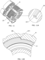
- the collet 3 and locking cap 4 are provided with a feature to prevent over-tightening as shown in Figs. 11, 11A and 11B .
- the screw thread 31 on the collet 3 is provided with an end stop 311.
- the screw thread 40 on the end cap 4 is provided with complementary end stop 44 which abuts against the end stop 31 to prevent further screwing of the end cap 4 onto the collet 3.
- the end stops 311 and 44 have face-to-face contact to provide an abrupt stop. One or both of these could have a ramped surface to provide a let abrupt end stop.
- the collet 3 and locking cap 4 also have features to provide an audible click when the locking cap 4 reaches the locked position.
- This is in the form of an angled lip 312 best shown in Fig. 8A which projects outwardly and distally from the outer face of the distal end of the collet 3.
- the lip 45 will ride over and compress the angled lips 32 whereupon, as the locking cap 4 reaches the fully locked position, the angled lips 312 will snap into position behind the lips 45.
- the lips 312 help retain the locking cap 4 on the collet 3 as they can be resiliently biased onto the lip 45 to hold the two components in place. This biasing can also help keep the components together when subject to small movements in use caused by thermal effects, or changes in flow of liquid through the pipes which might otherwise serve to work the connection loose over time.
- the collet 3 and locking cap 4 have a further feature which improves security of the connector.
- the annular lip 30 at the distal end of the collet 3 is exposed, in use, at the distal end of the end cap 4 when in the locked configuration.
- Fig. 8A is a cross-section through a plane of the collet 3 which is circumferentially offset from the second annular slots 34. However, in the vicinity of these slots the cross section would effectively be the same as in Fig. 8A same except that the collet 3 would not be visible in this plane. In practice, this means that the end of the pipe itself is visible through the slots 34 (best appreciated from Fig. 2C ) at the distal end of the collet 3.
- the above arrangement allows a user to determine that, in the locked position, the pipe itself is fully inserted within the connector.
- the body 1 is provided with a further feature which assist in this process. This is shown in Figs. 10 and 10A-C .
- the annular groove 12 in the tubular part 11 of the body 1 is provided with a bump 16 which projects upwardly from the bottom of the annular groove 12. The effect of this bump is shown in Figs. 10B and 10C .
- a gap 17 feature is formed on the radially innermost side of the O-ring 2. This corresponds to the configuration shown in Fig.
- FIG. 12-15 A second example of a connector is shown in Figs. 12-15 . These views correspond to Figs. 6-9 in relation to the first example. Many of the features of the second example are the same as those of the first example and have been designated with the same reference numerals.
- the difference between the two examples relates to the external profile of the tubular portion 11 and the fact that the O ring is now absent.
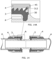
- the outer face of the tubular portion is provided with a number of axially-spaced annular barbs 110.
- these barbs have a gently tapering face 111 at the proximal end and an abrupt end face 112 at the distal end which is approximately in a radial plane.
- These provide a tooth-like structure which digs into and grips the pipe P as shown in Fig. 13A when the locking cap 4 is screwed into place compressing the collet 3.
- the barbs 110 therefore fulfil the same function as the O-ring 2 in the first example.
- the first example is provided with a number of crenulations 13 at the distal end of the tubular portion 11. No such portions are shown in relation to the second example, but could be present if desired.
- barbs 110 are shown in the drawings. This is a reasonable number to provide adequate grip and sealing in the available space. However, a bigger or smaller number of barbs can be used.
- the barbs 110 may also be used in combination with the O ring seal of the previous example.
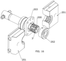
- Fig, 16 is a perspective view of the mould components shown in a separated form after the formation of the collet 3.
- the mould comprises an axial core 200 which forms the internal features of the collet as described below and a mould body which forms the outer features of the collet 3.
- the mould body comprises two mould halves 201 which are moved radially away from the collet as shown (in exaggerated form) in Fig.16 .
- the mould body also comprises manifold 202 which forms the end of the collet and is also provided with manifolds (not shown) through which the plastic is injected.
- the mould halves 201 and the manifold 202 are conventional and will not be described in further detail here.
- the mould also comprises an ejector plate 203 as described in greater detail below.
- the axial core 200 has an inner sleeve 204 which is hollow to allow cooling water to circulate.
- the first core mould part 205 is axially slidable on the inner sleeve 204 from a forward position in which it abuts second core mould part 206 to a rearward position as described below. This movement is driven by axial movement of an outer ring 207 engaging with a flange 208 on the first core mould part 205.
- the second core mould part 206 is axially fixed to the inner sleeve 204 by a bolt 209 and is provided in two parts, namely an end part 210 and intermediate part 211 which is held in place by being sandwiched between the end part 210 and a shoulder 212 on the inner sleeve 204.
- the external features of the collet 3 are formed by the mould halves 201 which are withdrawn radially and by the manifold 202 which is withdrawn axially in a manner well known in the art.
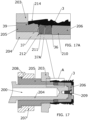
- Fig. 17A This shows a cross-section through one leg 35 of the collet. From the innermost edge 39, the inner diameter of the collet increases gradually forming a ramp 213. Axially spaced from the ramp 213 is the outer tooth 37, the inward bulge 37A and the inner tooth 36. The inner tooth 36 is formed at the junction between the end part 210 and the intermediate part 211 of the second core part 206. Similarly, the outer tooth 37 is formed at an interface between the first core mould portion 205 and the intermediate portion 211 of the second core portion 206.
- the ramp 213 is formed by a frustoconical face 214 on the first core mould part 205.
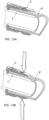
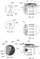
- the ring 207 is moved away from the mould cavity causing the first core mould part 205 to slide along the axial core 200 to the position shown in Figs. 18 and 18A .
- the frustoconical face 214 rides up the ramp 213 causing the legs 35 to be splayed radially outwardly. This peels the inner face of the collet 3 away from the second core mould part 206 and, in particular, away from the intermediate part 211.
- the ejector plate 203 is moved to the right thereby pushing on the end of the collet 3 to displace it from the second core mould part 206 as shown in Figs. 19 and 19A . Because of the above described interaction between the ramp 213 and frustoconical face 214, the inner tooth 37 is clear of the intermediate part 211. Further, in the position shown in Fig. 18A , the left flank of the inner tooth 36 is separated slightly from the intermediate part 211.
- the method provides a way of moulding a relatively complex geometry on the inner face of the collet, in a manner which can be simply and reliably demoulded.
- the body 1, O-ring 2, collet 3 and locking cap 4 broadly operate as described with reference to the first and second examples.
- the third example relates to a modification which can provide an audible click to a user to indicate that the connector has been fully made up.
- the third example is provided with a break-off tab 300 which projects radially outwardly at the opposite end of the collet to which it is attached by a frangible connection.
- a break-off tab 300 which projects radially outwardly at the opposite end of the collet to which it is attached by a frangible connection.
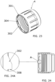
- the collet and cap are also provided with the end stop mechanism in the form of saw teeth recesses 302 which are formed in an inner face of the connector 4 so that they are open towards the end 301 of the locking cap 4 and complimentary saw teeth 303 on the collet.
- the end face 304 in the vicinity of the saw teeth recesses 302 engages with a complimentary face 305 on the collet.
- Ramp surfaces 306, 307 of the complimentary saw teeth ride up one another, thereby causing an increased resistance to further movement of the locking ring 4 until the saw teeth 303 drop into the saw teeth recesses 302 and ultimately their complimentary end faces 308, 309 provide an end stop to prevent further rotation of the locking cap 4 with respect to the collet 3.
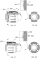
- this example has an array of bumps 402, 403 facing inwardly from an inner face of the distal end of the connector 4 and a corresponding array of bumps 403 projecting outwardly from a complimentary outer face of the collet 3.
- the locking cap 4 approaches its locked position, the user will feel and hear a vibration as the bumps 402, 403 ride over one another. This will occur shortly before the break-off tab is engaged by the locking cap 4 which will then produce an audible click as the tab is broken off and retained as set out above. Further movement of the locking cap 4 is then prevented by its engagement with the flange 401 and the intervening break-off tab 400.
- the user is provided with a series of audible and tactile signals indicating that they are approaching and have reached the fully locked position, whereupon further movement of the cap 4 is prevented.
Landscapes
- Engineering & Computer Science (AREA)
- General Engineering & Computer Science (AREA)
- Mechanical Engineering (AREA)
- Quick-Acting Or Multi-Walled Pipe Joints (AREA)
- Details Of Connecting Devices For Male And Female Coupling (AREA)
- Cable Accessories (AREA)
- Paper (AREA)
- Connector Housings Or Holding Contact Members (AREA)
Applications Claiming Priority (3)
| Application Number | Priority Date | Filing Date | Title |
|---|---|---|---|
| GB2011440.1A GB2597494B (en) | 2020-07-23 | 2020-07-23 | A plumbing connector |
| PCT/GB2021/051822 WO2022018413A1 (en) | 2020-07-23 | 2021-07-15 | A plumbing connector |
| EP21745402.4A EP4185799B1 (de) | 2020-07-23 | 2021-07-15 | Ein rohrleitungsanschluss |
Related Parent Applications (1)
| Application Number | Title | Priority Date | Filing Date |
|---|---|---|---|
| EP21745402.4A Division EP4185799B1 (de) | 2020-07-23 | 2021-07-15 | Ein rohrleitungsanschluss |
Publications (2)
| Publication Number | Publication Date |
|---|---|
| EP4530515A2 true EP4530515A2 (de) | 2025-04-02 |
| EP4530515A3 EP4530515A3 (de) | 2025-05-28 |
Family
ID=72339364
Family Applications (2)
| Application Number | Title | Priority Date | Filing Date |
|---|---|---|---|
| EP25157364.8A Pending EP4530515A3 (de) | 2020-07-23 | 2021-07-15 | Sanitärverbinder |
| EP21745402.4A Active EP4185799B1 (de) | 2020-07-23 | 2021-07-15 | Ein rohrleitungsanschluss |
Family Applications After (1)
| Application Number | Title | Priority Date | Filing Date |
|---|---|---|---|
| EP21745402.4A Active EP4185799B1 (de) | 2020-07-23 | 2021-07-15 | Ein rohrleitungsanschluss |
Country Status (6)
| Country | Link |
|---|---|
| EP (2) | EP4530515A3 (de) |
| CN (2) | CN118532567A (de) |
| AU (1) | AU2021312366A1 (de) |
| ES (1) | ES3030514T3 (de) |
| GB (1) | GB2597494B (de) |
| WO (1) | WO2022018413A1 (de) |
Families Citing this family (8)
| Publication number | Priority date | Publication date | Assignee | Title |
|---|---|---|---|---|
| USD1097081S1 (en) | 2021-10-05 | 2025-10-07 | Reliance Worldwide Corporation (UK) Limited | Connector |
| US20230313920A1 (en) * | 2022-03-31 | 2023-10-05 | Donald Stott | Hose attachment fitting |
| US20260049681A1 (en) * | 2022-08-11 | 2026-02-19 | Elysee Irrigation Ltd. | Connector, pipe system and assembling process |
| GB202214413D0 (en) | 2022-09-30 | 2022-11-16 | Reliance Worldwide Corporation Uk Ltd | A tube connector |
| GB2625100A (en) | 2022-12-06 | 2024-06-12 | Reliance Worldwide Corporation Uk Ltd | A plumbing connector |
| GB2637127A (en) * | 2023-12-22 | 2025-07-16 | Reliance Worldwide Corporation Uk Ltd | A plumbing connector |
| WO2025141856A1 (ja) * | 2023-12-28 | 2025-07-03 | ニッタ株式会社 | 管継手 |
| AT18454U1 (de) * | 2024-04-03 | 2025-04-15 | Ke Kelit Gmbh | Anschlussvorrichtung für ein Kunststoffrohr |
Citations (6)
| Publication number | Priority date | Publication date | Assignee | Title |
|---|---|---|---|---|
| EP0168260A2 (de) | 1984-07-13 | 1986-01-15 | Sekisui Kagaku Kogyo Kabushiki Kaisha | Rohrverbindung |
| EP0206582A2 (de) | 1985-06-11 | 1986-12-30 | Hozelock-ASL Limited | Rohrkupplung |
| EP1860260A1 (de) | 2005-05-13 | 2007-11-28 | Illinois Tool Works Inc. | Türgriffanordnung |
| WO2011099519A1 (ja) | 2010-02-10 | 2011-08-18 | 日本フレックス株式会社 | ホースコネクタ |
| JP2011247335A (ja) | 2010-05-26 | 2011-12-08 | Nippon Flex Kk | ホースコネクタ |
| WO2015089583A2 (en) | 2013-12-19 | 2015-06-25 | Gsa Industries (Aust.) Pty Ltd | Pipe connection fitting |
Family Cites Families (1)
| Publication number | Priority date | Publication date | Assignee | Title |
|---|---|---|---|---|
| WO2015029815A1 (ja) * | 2013-08-30 | 2015-03-05 | 株式会社トヨックス | 管継手 |
-
2020
- 2020-07-23 GB GB2011440.1A patent/GB2597494B/en active Active
-
2021
- 2021-07-15 EP EP25157364.8A patent/EP4530515A3/de active Pending
- 2021-07-15 EP EP21745402.4A patent/EP4185799B1/de active Active
- 2021-07-15 AU AU2021312366A patent/AU2021312366A1/en active Pending
- 2021-07-15 WO PCT/GB2021/051822 patent/WO2022018413A1/en not_active Ceased
- 2021-07-15 CN CN202410568235.4A patent/CN118532567A/zh active Pending
- 2021-07-15 ES ES21745402T patent/ES3030514T3/es active Active
- 2021-07-15 CN CN202180065051.0A patent/CN116547469A/zh active Pending
Patent Citations (6)
| Publication number | Priority date | Publication date | Assignee | Title |
|---|---|---|---|---|
| EP0168260A2 (de) | 1984-07-13 | 1986-01-15 | Sekisui Kagaku Kogyo Kabushiki Kaisha | Rohrverbindung |
| EP0206582A2 (de) | 1985-06-11 | 1986-12-30 | Hozelock-ASL Limited | Rohrkupplung |
| EP1860260A1 (de) | 2005-05-13 | 2007-11-28 | Illinois Tool Works Inc. | Türgriffanordnung |
| WO2011099519A1 (ja) | 2010-02-10 | 2011-08-18 | 日本フレックス株式会社 | ホースコネクタ |
| JP2011247335A (ja) | 2010-05-26 | 2011-12-08 | Nippon Flex Kk | ホースコネクタ |
| WO2015089583A2 (en) | 2013-12-19 | 2015-06-25 | Gsa Industries (Aust.) Pty Ltd | Pipe connection fitting |
Also Published As
| Publication number | Publication date |
|---|---|
| GB2597494B (en) | 2022-12-21 |
| AU2021312366A1 (en) | 2023-03-09 |
| EP4185799B1 (de) | 2025-03-12 |
| WO2022018413A1 (en) | 2022-01-27 |
| EP4530515A3 (de) | 2025-05-28 |
| EP4185799A1 (de) | 2023-05-31 |
| ES3030514T3 (en) | 2025-06-30 |
| GB202011440D0 (en) | 2020-09-09 |
| GB2597494A (en) | 2022-02-02 |
| CN118532567A (zh) | 2024-08-23 |
| CN116547469A (zh) | 2023-08-04 |
Similar Documents
| Publication | Publication Date | Title |
|---|---|---|
| EP4185799B1 (de) | Ein rohrleitungsanschluss | |
| EP4185798B1 (de) | Ein rohrleitungsanschluss | |
| US20230265952A1 (en) | A plumbing connector | |
| EP0655577B1 (de) | Rohrkupplungsanordnung | |
| US4647086A (en) | Tube coupling | |
| CA2459637C (en) | Pipe coupling | |
| CN107110406A (zh) | 用于连接至管形件、管路连接的接头以及用于将接头连接至管形件的方法 | |
| JP2001124258A (ja) | 管継手 | |
| JP5269178B2 (ja) | 管継手の組立て方法 | |
| US7681929B1 (en) | Pipe coupler for metal to plastic pipe | |
| JP4939826B2 (ja) | 管継手の組立て方法 | |
| CA2637939A1 (en) | Adaptor and method for converting standard tube fitting/port to push-to-connect tube fitting/port | |
| EP1800047B1 (de) | Rohrkupplung | |
| JP5395971B2 (ja) | 管継手及び閉鎖バルブ | |
| AU2023391245A1 (en) | A plumbing connector | |
| JP3762380B2 (ja) | 可撓管継手 | |
| JP2000266252A (ja) | 管継手 | |
| JP4597889B2 (ja) | 管継手 | |
| JP2006132694A (ja) | メカニカルタイプの管継手 | |
| JP2024142551A (ja) | 接続具用取付方法及び接続具 | |
| JP2013242040A (ja) | 管継手及び閉鎖バルブ | |
| HK1204672A1 (zh) | 管连接器 | |
| HK1123595A1 (en) | A coupling system for polymeric pipes | |
| HK1204672B (en) | Tube joint |
Legal Events
| Date | Code | Title | Description |
|---|---|---|---|
| PUAI | Public reference made under article 153(3) epc to a published international application that has entered the european phase |
Free format text: ORIGINAL CODE: 0009012 |
|
| STAA | Information on the status of an ep patent application or granted ep patent |
Free format text: STATUS: THE APPLICATION HAS BEEN PUBLISHED |
|
| AC | Divisional application: reference to earlier application |
Ref document number: 4185799 Country of ref document: EP Kind code of ref document: P |
|
| AK | Designated contracting states |
Kind code of ref document: A2 Designated state(s): AL AT BE BG CH CY CZ DE DK EE ES FI FR GB GR HR HU IE IS IT LI LT LU LV MC MK MT NL NO PL PT RO RS SE SI SK SM TR |
|
| PUAL | Search report despatched |
Free format text: ORIGINAL CODE: 0009013 |
|
| AK | Designated contracting states |
Kind code of ref document: A3 Designated state(s): AL AT BE BG CH CY CZ DE DK EE ES FI FR GB GR HR HU IE IS IT LI LT LU LV MC MK MT NL NO PL PT RO RS SE SI SK SM TR |
|
| RIC1 | Information provided on ipc code assigned before grant |
Ipc: F16L 33/22 20060101AFI20250424BHEP |
|
| STAA | Information on the status of an ep patent application or granted ep patent |
Free format text: STATUS: REQUEST FOR EXAMINATION WAS MADE |
|
| 17P | Request for examination filed |
Effective date: 20251127 |
|
| GRAP | Despatch of communication of intention to grant a patent |
Free format text: ORIGINAL CODE: EPIDOSNIGR1 |
|
| STAA | Information on the status of an ep patent application or granted ep patent |
Free format text: STATUS: GRANT OF PATENT IS INTENDED |