EP4530550A1 - Klimaanlage - Google Patents
Klimaanlage Download PDFInfo
- Publication number
- EP4530550A1 EP4530550A1 EP24202405.7A EP24202405A EP4530550A1 EP 4530550 A1 EP4530550 A1 EP 4530550A1 EP 24202405 A EP24202405 A EP 24202405A EP 4530550 A1 EP4530550 A1 EP 4530550A1
- Authority
- EP
- European Patent Office
- Prior art keywords
- indoor
- indoor unit
- air conditioner
- unit
- units
- Prior art date
- Legal status (The legal status is an assumption and is not a legal conclusion. Google has not performed a legal analysis and makes no representation as to the accuracy of the status listed.)
- Pending
Links
Images



Classifications
-
- F—MECHANICAL ENGINEERING; LIGHTING; HEATING; WEAPONS; BLASTING
- F24—HEATING; RANGES; VENTILATING
- F24F—AIR-CONDITIONING; AIR-HUMIDIFICATION; VENTILATION; USE OF AIR CURRENTS FOR SCREENING
- F24F11/00—Control or safety arrangements
- F24F11/62—Control or safety arrangements characterised by the type of control or by internal processing, e.g. using fuzzy logic, adaptive control or estimation of values
- F24F11/63—Electronic processing
- F24F11/64—Electronic processing using pre-stored data
-
- F—MECHANICAL ENGINEERING; LIGHTING; HEATING; WEAPONS; BLASTING
- F24—HEATING; RANGES; VENTILATING
- F24F—AIR-CONDITIONING; AIR-HUMIDIFICATION; VENTILATION; USE OF AIR CURRENTS FOR SCREENING
- F24F11/00—Control or safety arrangements
- F24F11/62—Control or safety arrangements characterised by the type of control or by internal processing, e.g. using fuzzy logic, adaptive control or estimation of values
- F24F11/63—Electronic processing
-
- F—MECHANICAL ENGINEERING; LIGHTING; HEATING; WEAPONS; BLASTING
- F24—HEATING; RANGES; VENTILATING
- F24F—AIR-CONDITIONING; AIR-HUMIDIFICATION; VENTILATION; USE OF AIR CURRENTS FOR SCREENING
- F24F11/00—Control or safety arrangements
- F24F11/30—Control or safety arrangements for purposes related to the operation of the system, e.g. for safety or monitoring
- F24F11/46—Improving electric energy efficiency or saving
-
- F—MECHANICAL ENGINEERING; LIGHTING; HEATING; WEAPONS; BLASTING
- F24—HEATING; RANGES; VENTILATING
- F24F—AIR-CONDITIONING; AIR-HUMIDIFICATION; VENTILATION; USE OF AIR CURRENTS FOR SCREENING
- F24F11/00—Control or safety arrangements
- F24F11/50—Control or safety arrangements characterised by user interfaces or communication
- F24F11/54—Control or safety arrangements characterised by user interfaces or communication using one central controller connected to several sub-controllers
-
- F—MECHANICAL ENGINEERING; LIGHTING; HEATING; WEAPONS; BLASTING
- F24—HEATING; RANGES; VENTILATING
- F24F—AIR-CONDITIONING; AIR-HUMIDIFICATION; VENTILATION; USE OF AIR CURRENTS FOR SCREENING
- F24F11/00—Control or safety arrangements
- F24F11/70—Control systems characterised by their outputs; Constructional details thereof
- F24F11/80—Control systems characterised by their outputs; Constructional details thereof for controlling the temperature of the supplied air
-
- F—MECHANICAL ENGINEERING; LIGHTING; HEATING; WEAPONS; BLASTING
- F24—HEATING; RANGES; VENTILATING
- F24F—AIR-CONDITIONING; AIR-HUMIDIFICATION; VENTILATION; USE OF AIR CURRENTS FOR SCREENING
- F24F2110/00—Control inputs relating to air properties
- F24F2110/10—Temperature
-
- F—MECHANICAL ENGINEERING; LIGHTING; HEATING; WEAPONS; BLASTING
- F25—REFRIGERATION OR COOLING; COMBINED HEATING AND REFRIGERATION SYSTEMS; HEAT PUMP SYSTEMS; MANUFACTURE OR STORAGE OF ICE; LIQUEFACTION SOLIDIFICATION OF GASES
- F25B—REFRIGERATION MACHINES, PLANTS OR SYSTEMS; COMBINED HEATING AND REFRIGERATION SYSTEMS; HEAT PUMP SYSTEMS
- F25B2313/00—Compression machines, plants or systems with reversible cycle not otherwise provided for
- F25B2313/023—Compression machines, plants or systems with reversible cycle not otherwise provided for using multiple indoor units
- F25B2313/0233—Compression machines, plants or systems with reversible cycle not otherwise provided for using multiple indoor units in parallel arrangements
Definitions
- the present disclosure relates to an air conditioner, and particularly, to an air conditioner which may control operations of a plurality of indoor units disposed in a plurality of regions constituting an indoor space, respectively.
- an air conditioner In order to create a pleasant indoor environment, an air conditioner is installed to provide humans with a more comfortable indoor environment by discharging the air at a cold hot temperature to the room to adjust a room temperature and purify indoor air.
- the air conditioner includes an indoor unit constituted by a heat exchanger and installed in the room, and an outdoor unit constituted by a compressor and the heat exchanger, and supplying refrigerant to the indoor unit.
- the air conditioner is cooling-operated or heating-operated according to the flow of the refrigerant.
- high-temperature and high-pressure liquid refrigerant is supplied to the indoor unit from the compressor of the outdoor unit via the heat exchanger of the outdoor unit, and a temperature of surrounding air is lowered while the refrigerant is expanded and vaporized in the heat exchanger of the indoor unit, and as an indoor unit fan rotates, cooling air is discharged to the room.
- high-temperature and high-pressure gas refrigerant is supplied to the indoor unit from the compressor of the outdoor unit, and air which is warmed by energy emitted while the high-temperature and high-pressure gas refrigerant is liquefied is discharged to the room according to an operation of the indoor fan in the heat exchanger of the indoor unit.
- cooling-temperature air can be supplied to each of a plurality of regions of an indoor space by using the plurality of indoor units. Further, cooling-temperature air discharged from a specific indoor unit can influence a region corresponding to the specific indoor unit, and the other region adjacent thereto. As described above, it is necessary to study a method for more efficiently controlling operations of the indoor units by considering a correlation between indoor units in the case of cooling and heating the indoor space by using the plurality of indoor units.
- the present disclosure solves the above-described problems and other problems.
- the present disclosure also provides an air conditioner capable of controlling a support operation of an indoor unit adjacent to a predetermined region so that an indoor temperature of the predetermined region quickly reaches a target temperature.
- the present disclosure also provides an air conditioner capable of determining an optimal indoor unit which is to be used for an operation support for the predetermined region.
- an air conditioner may include: an outdoor unit; a plurality of indoor units disposed to correspond to a plurality of regions, respectively; temperature sensors sensing indoor temperatures for the plurality of regions corresponding to the plurality of indoor units, respectively; and a controller, and the controller may set, when there is at least one first indoor unit in which an indoor temperature of a corresponding region is lower than a target temperature among the plurality of indoor units, any one of the first indoor units to a second indoor unit requiring an operation support, based on a difference between the target temperature and the indoor temperature, set any one of indoor units which are adjacent to the second indoor unit, and of which powers are off to a third indoor unit that supports an operation of the second indoor unit, and control the operation by turning on a power of the third indoor unit.
- the indoor temperature of the predetermined region may quickly reach the target temperature through the support operation of the indoor unit adjacent to the predetermined region.
- the optimal indoor unit may be determined, which is to be used for the operation support for the predetermined region.
- a sample detection device 1 may obtain an enlarged image of a sample 3 using light emitted from a light source 2.
- module and unit for components used in the following description are given in consideration of easy preparation of the specification only and do not have their own particularly important meanings or roles. Accordingly, the “module” and “unit” may be used interchangeably.
- first, second, etc. may be used for describing various components, but the components are not limited by the terms. The terms are used for distinguishing one component from another component.
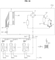
- FIGS. 1A and 1B are diagrams illustrating a configuration of an air conditioner according to an embodiment of the present disclosure.
- the air conditioner may include an outdoor unit ODU and an indoor unit IDU connected to each other by a refrigerant pipe.
- the air conditioner may further include a remote control unit (RCU).
- the outdoor unit ODU, the indoor unit IDU, and/or the remote control unit RCU may transmit and receive signals to and from each other.
- the outdoor unit ODU may include a compressor 1, an oil separator 2, a switching valve 3, an outdoor heat exchanger 4, an outdoor expansion valve E2, and/or an accumulator 6.
- the outdoor unit IDU may include an indoor heat exchanger 5 and an indoor expansion valve E1.
- the compressor 1 may compress refrigerant introduced from the accumulator 6 at high temperature and at high pressure.
- the compressor 1 may be an inverter compressor that adjusts an operating frequency to control a refrigerant amount and s discharge pressure of the refrigerant.
- the compressor 1 may be an oil compressor using oil as a lubricant.
- the oil separator 2 may recover the oil from the refrigerant discharged from the compressor 1, and provide the recovered oil to the compressor 1 again.
- a first check valve C1 is installed in a pipe in which the oil separated by the oil separator 2 flows, and a flowing direction of the oil may be limited to a direction from the oil separator 2 to the compressor 1.
- the switching valve 3 may selectively guide the refrigerant introduced from the oil separator 2 to the outdoor heat exchanger 4 or the indoor heat exchanger 5.
- the switching valve 3 may be a 4-way valve.
- the outdoor heat exchanger 4 may heat-exchange the refrigerant and outdoor air.
- a heat transfer direction between the refrigerant and the outdoor air in the outdoor heat exchanger 4 may vary depending on an operation mode of the air conditioner, i.e., the heating operation or the cooling operation.
- An outdoor fan (not illustrated) is installed at one side of the outdoor heat exchanger 4 to adjust the amount of air provided to the outdoor heat exchanger 4.
- the indoor heat exchanger 5 may heat-exchange the refrigerant and indoor air.
- a heat transfer direction between the refrigerant and the indoor air in the indoor heat exchanger 5 may vary depending on the operation mode of the air conditioner, i.e., the heating operation or the cooling operation.
- An indoor fan (not illustrated) is installed at one side of the indoor heat exchanger 5 to adjust the amount of air provided to the indoor heat exchanger 5.
- the indoor heat exchanger 5 may include a plurality of indoor heat exchangers 5a, 5b, and 5c.
- the indoor unit IDU may include a first outdoor unit IDUa including a first indoor heat exchanger 5a, a first indoor fan, and a first indoor expansion valve E1a, a second indoor unit IDUb including a second indoor heat exchanger 5b, a second indoor fan, and a second indoor expansion valve E1b, and a third indoor unit IDUc including a third indoor heat exchanger 5c, a third indoor fan, and a third indoor expansion valve E1c.
- some of the plurality of indoor heat exchangers 5a, 5b, and 5c may be operated, and the remaining indoor heat exchangers may be non-operated, in response to a cooling or heating required load of the room.
- the expansion valves E1 and E2 are installed between the outdoor heat exchanger 4 and the indoor heat exchange 5 to expand the refrigerant which passes through the outdoor heat exchanger 4 or the indoor heat exchanger 5.
- the expansion valves E1 and E2 may include the outdoor expansion valve E2 adjacent to the outdoor heat exchanger 4 and the indoor expansion valve E1 adjacent to the indoor heat exchanger 5.
- the outdoor expansion valve E2 may be used for expanding the refrigerant which passes through the indoor heat exchanger 5
- the indoor expansion valve E1 may be used for expanding the refrigerant which passes through the outdoor heat exchanger 4.
- the expansion valves E1 and E2 may be electronic expansion valves (EEVs) capable of adjusting an opening level of a path of the refrigerant pipe in which the expansion valves E1 and E2 are installed.
- the indoor expansion valve E1 may include a first indoor expansion valve E1a expanding the refrigerant provided to the first indoor heat exchanger 5a, a second indoor expansion valve E1b expanding the refrigerant provided to the second indoor heat exchanger 5b, and a third indoor expansion valve E1c expanding the refrigerant provided to the third indoor heat exchanger 5c.
- a plurality of sensors may measure a temperature and/or a pressure of the refrigerant which flows in the refrigerant pipe.
- a controller (not illustrated) is electrically connected to each component of the air conditioner to control the operation of each component of the air conditioner.
- the controller may perform the heating operation of the air conditioner.
- the heating operation signal may be a signal arbitrarily input by a user.
- the heating operation signal may be a signal which a thermostat provided in the indoor space provides to the controller when an indoor temperature sensed by an indoor-side temperature sensor is lower than a desired temperature set by the user by a predetermined level or more.
- low-temperature and low-pressure refrigerant which is introduced from the accumulator 6 into the compressor 1 may be compressed at the high temperature and the high pressure by the compressor 1 and discharged to the oil separator 2.
- the refrigerant from which the oil is separated by the oil separator 2 may be introduced into the second indoor heat exchanger 5b via the switching valve 3 and a first service valve SV1.
- the second indoor expansion valve E1b may completely open a path of the refrigerant, which is linked to the outdoor heat exchanger 4 by passing through the second indoor heat exchanger 5b.
- first indoor expansion valve E1a and a third indoor expansion valve E1c may close a path of the refrigerant, which is linked to the outdoor heat exchanger 4 by passing through the first indoor heat exchanger 5a and the third indoor heat exchanger 5c. Further, when a required heating load increases, the first indoor expansion valve E1a and/or the third indoor expansion valve E1c may also be opened.
- the refrigerant may be condensed.
- the second indoor heat exchanger 5b may serve as a condenser.
- the indoor space may be heated according to the heat exchange between the refrigerant and the indoor air.
- the refrigerant condensed while passing through the second indoor heat exchanger 5b may pass through the outdoor expansion valve E2 via the second indoor expansion valve E1b and a second service valve SV2.
- Refrigerant expanded while passing through the outdoor expansion valve E2 may be distributed to a plurality of points of the outdoor heat exchanger 4 via a distributor 41.
- the refrigerant may be evaporated.
- the outdoor heat exchanger 4 may serve as an evaporator.
- the refrigerant evaporated while passing through the outdoor heat exchanger 4 may be introduced into the compressor 1 via a header 42, the switching valve 3, and the accumulator 6 sequentially. As a result, a refrigerant cycle for the heating operation of the air conditioner may be completed.
- the controller may perform a cooling operation of the air conditioner.
- the cooling operation signal may be a signal arbitrarily input by the user.
- the cooling operation signal may be a signal which the thermostat provided in the indoor space provides to the controller when the indoor temperature sensed by the indoor-side temperature sensor is higher than a desired temperature set by the user by a predetermined level or more.
- the low-temperature and low-pressure refrigerant which is introduced from the accumulator 6 into the compressor 1 may be compressed at the high temperature and the high pressure by the compressor 1 and discharged to the oil separator 2.
- the refrigerant from which the oil is separated by the oil separator 2 may be introduced into the outdoor heat exchanger 4 via the switching valve 3 and the header 42.
- the refrigerant may be condensed.
- the outdoor heat exchanger 4 may serve as the condenser.
- the refrigerant condensed while passing through the outdoor heat exchanger 4 may be introduced into the second indoor expansion valve E1b via the distributor 41, the outdoor expansion valve E2, and the second service valve SV2 sequentially.
- the outdoor expansion valve E2 may completely open the path.
- the refrigerant expanded while passing through the second indoor expansion valve E1b may be introduced into the second indoor heat exchanger 5b.
- the first indoor expansion valve E1a and/or the third indoor expansion valve E1c may also be opened at a predetermined opening level.
- the refrigerant may be evaporated.
- the second indoor heat exchanger 5b may serve as an evaporator.
- the indoor space may be cooled according to the heat exchange between the refrigerant and the indoor air.
- the refrigerant evaporated while passing through the second indoor heat exchanger 5b may be introduced into the compressor 1 via the first service valve SV1, the switching valve 3, and the accumulator 6 sequentially. As a result, a refrigerant cycle for the cooling operation of the air conditioner may be completed.
- the air conditioner according to the present disclosure performs the cooling operation, but the present is not limited thereto, and the present disclosure may be applied to the case where the air conditioner performs the heating operation in the same manner or similarly.
- FIG. 2 is a diagram referenced for describing an air conditioner including a plurality of indoor units according to an embodiment of the present disclosure.
- a plurality of indoor units IDUa to IDUn may be connected to at least one outdoor unit ODU through the refrigerant pipe.
- the plurality of indoor units IDUa to IDUn may be installed in the indoor space to be spaced apart from each other.
- the plurality of indoor units IDUa to IDUn may occupy a plurality of regions constituting the indoor space, respectively. Meanwhile, two or more of the plurality of indoor units IDUa to IDUn may also occupy one of a plurality of regions constituting the indoor space.
- the indoor unit IDU is a ceiling type, but is not limited thereto.
- the indoor unit IDU may include a suction hole 51 providing the indoor air to the indoor heat exchanger 5 of the indoor unit IDU, and a discharge hole 52 discharging the air which passes through the indoor heat exchanger 5 to the room, in response to the operation of the indoor fan.
- the indoor unit IDU may include a vane 53 which is movably installed in the discharge hole 52, and adjusts a direction of the air discharged to the room from the discharge hole 52.
- the indoor unit IDU includes a plurality of vanes 53 corresponding to four directions.
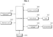
- FIG. 3 is a block diagram of the air conditioner according to an embodiment of the present disclosure.
- the air conditioner may include a communication interface 310, a sensor unit 320, a memory 330, a fan driver 340 driving a fan 351, a compressor driver 350 driving a compressor 341 (the compressor 1 of FIG. 1A ), and/or a controller 370.
- the communication interface 310 may include at least one communication module.
- the communication interface 310 may be provided in each of the outdoor unit ODU and the indoor unit IDU, and the outdoor unit ODU and the indoor unit IDU may transmit/receive data to/from each other.
- the communication interface 310 may be provided in the remote control unit RCU.
- a communication scheme of the outdoor unit ODU, the indoor unit IDU, and/or the remote control unit RCU may be, for example, a wireless communication scheme such as Wi-fi, Bluetooth, Beacon, ZigBee, etc., in addition to a wired communication scheme using a power line, a serial communication scheme (e.g., RS-485 communication), and a wired communication scheme through the refrigerant pipe.
- a wireless communication scheme such as Wi-fi, Bluetooth, Beacon, ZigBee, etc.
- a serial communication scheme e.g., RS-485 communication
- the communication interface 310 may mutually transmit/receive data to/from an external device.
- the communication interface 310 may also transmit/receive data by accessing a server connected to an external network.
- the sensor unit 320 may include at least one sensor, and transmit data for a detection value detected through the sensor to the controller 370.
- the sensor unit 320 may include a heat exchanger temperature sensor (not illustrated).
- the heat exchanger temperature sensor may be disposed inside the indoor heat exchanger 5, and may detect a temperature of the indoor heat exchanger 5.
- the sensor unit 320 may include a pipe temperature sensor (not illustrated).
- the pipe temperature sensor may detect a temperature of refrigerant which flows through each pipe of the air conditioner.
- the pipe temperature sensor may be disposed at an inlet-side pipe of the indoor unit IDU and/or an outlet-side pipe of the indoor unit IDU, and may detect the temperature of the refrigerant which flows through the pipe.
- the pipe temperature sensor may be disposed on a pipe connected to the compressor 341, and may detect a temperature (hereinafter, referred to as a suction temperature) of refrigerant introduced into the compressor 341 and/or a temperature (hereinafter, referred to as a discharge temperature) of refrigerant discharged from the compressor 341.
- the sensor unit 310 may include a pressure sensor (not illustrated).
- the pressure sensor (not illustrated) may detect a pressure of gas refrigerant which flows through each pipe of the air conditioner.
- the pressure sensor may be disposed on the pipe connected to the compressor 341, and may detect a pressure (hereinafter, referred to as a suction pressure) of the refrigerant introduced into the compressor 341 and/or a pressure (hereinafter, referred to as a discharge pressure) of the refrigerant discharged from the compressor 341.
- the sensor unit 320 may include an indoor temperature sensor (not illustrated) detecting an indoor temperature and/or an outdoor temperature sensor (not illustrated) detecting an outdoor temperature.
- the sensor unit 320 may include an indoor humidity sensor (not illustrated) detecting an indoor humidity and/or an outdoor humidity sensor (not illustrated) detecting an outdoor humidity.
- the memory 330 may store data for a reference value related to the operation of each component provided in the air conditioner.
- the memory 330 may store a program for processing and controlling each signal in the controller 370, and store processed data and data to be processed.
- the memory 330 may store application programs designed for a purpose of performing various tasks which are enabled to be processed by the controller 370, and selectively provide some of the stored application programs upon a request by the controller 370.
- the memory 330 may include, for example, at least one of a volatile memory (e.g., DRAM, SRAM, SDRAM, etc.) or a non-volatile memory (e.g., a flash memory, a hard disk drive (HDD), a solid-state drive (SSD), etc.).
- a volatile memory e.g., DRAM, SRAM, SDRAM, etc.
- a non-volatile memory e.g., a flash memory, a hard disk drive (HDD), a solid-state drive (SSD), etc.
- the fan driver 340 may drive the fan 351 provided in the air conditioner.
- the fan 351 may include an outdoor fan and/or an indoor fan.
- the fan driver 340 may include a rectifier (not illustrated) rectifying and outputting an alternating current (AC) power into a direct current (DC) power, and outputting the DC power, a dc-terminal capacitor (not illustrated) storing a pulse voltage from the rectifier, an inverter (not illustrated) including a plurality of switching elements, and converting and outputting a smoothed DC power into a 3-phase AC power having a predetermined frequency, and/or at least one motor driving the fan 351 driving the fan 351 according to the 3-phase AC power output from the inverter.
- a rectifier (not illustrated) rectifying and outputting an alternating current (AC) power into a direct current (DC) power, and outputting the DC power
- a dc-terminal capacitor not illustrated
- an inverter including a plurality of switching elements, and converting and outputting a smoothed DC power into a 3-phase AC power having a predetermined frequency
- the fan driver 340 may separately include components for driving the outdoor fan and the indoor fan, respectively.
- the air conditioner may include a first fan driver for driving the outdoor fan and a second fan driver for driving the indoor fan.
- the compressor driver 350 may drive the compressor 341.
- the compressor driver 350 may include a rectifier (not illustrated) rectifying and outputting the alternating current (AC) power into the direct current (DC) power, and outputting the DC power, a dc-terminal capacitor (not illustrated) storing the pulse voltage from the rectifier, an inverter (not illustrated) including the plurality of switching elements, and converting and outputting the smoothed DC power into the 3-phase AC power having a predetermined frequency, and/or a compressor motor 102b driving the compressor 341 according to the 3-phase AC power output from the inverter.
- the controller 370 may control an overall operation of the air conditioner.
- the controller 370 may connected to each component provided in the air conditioner, and transmits and/or receives a signal to/from each component to control the overall operation of each component.
- the controller 370 controls an operation of the fan driver 340 to change an RPM of the fan 351.
- the fan driver 340 changes the frequency of the 3-phase AC power output to an outdoor fan motor according to the control by the controller 370 to change an RPM of the outdoor fan.
- the fan driver 340 changes the frequency of the 3-phase AC power output to the outdoor fan motor according to the control by the controller 370 to change an RPM of the indoor fan.
- the controller 370 controls an operation of the compressor driver 350 to change an operating frequency of the compressor 341.
- the compressor driver 350 changes the frequency of the 3-phase AC power output to the compressor motor 102b according to the control by the controller 370 to change the operating frequency of the compressor 341.
- the controller 370 may also be provided in the indoor unit IDU, the outdoor unit ODU, and/or the remote control unit RCU.
- the controller 370 may include at least one processor, and control an overall operation of the air conditioner by using a processor included in the controller 370.
- the processor may be a general processor such as a central processing unit (CPU).
- the processor a dedicated device such as ASIC or another hardware based processor.
- the controller 370 may acquire data related to each component provided in the air conditioner. In this case, the controller 370 may also acquire the data related to each component provided in the air conditioner at a predetermined time interval according to a predetermined cycle by considering a computational load.
- the controller 370 may perform various computations based on the acquired data, and control the overall operation of each component provided in the air conditioner according to a computational result.
- the data related to each component provided in the air conditioner may include, for example, the operating frequency of the compressor 341, the suction temperature, the discharge temperature, the suction pressure, and the discharge pressure of the compressor 341, the inlet-side pipe temperature of the indoor unit IDU, the outlet-side pipe temperature of the indoor unit IDU, the indoor temperature, the outdoor temperature, the opening level of the electronic expansion valve EEV, etc.
- the air conditioner may further include an input device (not illustrated) which may receive a user input.
- the input device e.g., a touch panel, a key, etc.
- the air conditioner may perform an operation corresponding to the received user input.
- the air conditioner may further include an output interface 360 which outputs a message for an operating state.
- the output interface 360 may include a display device such as a display, a light emitting diode (LED), etc., and/or an audio device such as a speaker, a buzzer, etc.
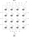
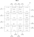
- FIG. 4 is a diagram referenced for describing locations of a plurality of indoor units disposed in an indoor space according to an embodiment of the present disclosure.
- a plurality of indoor units IDU11 to IDU44 may be disposed in an indoor space 400.
- the plurality of indoor units IDU11 to IDU44 may correspond to a plurality of regions 411 to 444 constituting the indoor space 400, respectively.
- the plurality of regions 411 to 444 constituting the indoor space 400 may be in communication with each other.
- Operating the plurality of indoor units IDU11 to IDU44 may influence an adjacent region. For example, when the air conditioner performs the cooling operation while a first indoor unit IDU11 is in operation, cooling air may be discharged from the first indoor unit IDU11 to a first region 411. In this case, a temperature of the first region 411 may be lowered by the cooling air discharged from the first indoor unit IDU11. Meanwhile, as the temperature of the first region 411 is lowered, temperatures of a second region 412 and a fifth region 421 adjacent to the first region 411 may be lowered.
- Each of the plurality of indoor units IDU11 to IDU44 may acquire data regarding a corresponding region among the plurality of regions 411 to 444.
- each of the plurality of indoor units IDU11 to IDU44 may detect an indoor temperature and/or an indoor humidity of a corresponding region among the plurality of regions 411 to 444.
- the air conditioner may store location information of the plurality of indoor units IDU11 to IDU44.
- location information of the plurality of indoor units IDU11 to IDU44 may be coordinates.
- the location information of the plurality of indoor units IDU11 to IDU44 may be registered by a user. For example, the user may input the location information of the plurality of indoor units IDU11 to IDU44 through the input device included in the remote control unit RCU.
- the location information of the plurality of indoor units IDU11 to IDU44 may be transmitted to the plurality of indoor units IDU11 to IDU44, respectively.
- Each of the plurality of indoor units IDU11 to IDU44 may acquire data regarding an adjacent indoor unit based on the location information of the plurality of indoor units IDU11 to IDU44.
- an indoor unit adjacent to the first indoor unit IDU11 may be a second indoor unit IDU 12 and a fifth indoor unit IDU21.
- an indoor unit adjacent to a sixth indoor unit IDU22 may be the second indoor unit IDU12, the fifth indoor unit IDU21, a seventh indoor unit IDU23, and a tenth indoor unit IDU32.
- each of the plurality of indoor units IDU11 to IDU44 may collect regarding another indoor unit by using a depth-first search (DFS) algorithm.
- each of the plurality of indoor units IDU11 to IDU44 may acquire an operating state of another indoor unit, an indoor temperature of a region corresponding to another indoor unit, etc.
- the air conditioner may include indoor temperature sensors that sense indoor temperatures for the plurality of regions 411 to 444 corresponding to the plurality of indoor units IDU11 to IDU44, respectively.
- the indoor temperature sensor may be disposed in the plurality of indoor units IDU11 to IDU44, respectively.
- the remote control unit RCU may acquire data regarding the plurality of indoor units IDU11 to IDU44 based on the location information of the plurality of indoor units IDU11 to IDU44.
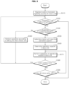
- FIG. 5 is a flowchart for an operating method of an air conditioner according to an embodiment of the present disclosure. A detailed description of contents duplicated with the contents described in FIGS. 1A to 4 will be omitted.
- the air conditioner may register location information for a plurality of indoor units IDU in operation S510.
- the air conditioner may register the location information for the plurality of indoor units IDU based on coordinates corresponding to the plurality of indoor units IDU, which are received through the remote control unit RCU, respectively.
- the air conditioner may check whether powers of one or more indoor units IDU among the plurality of indoor units IDU are on in operation S520.
- the air conditioner may determine whether there is an indoor unit IDU requiring the operation support when the powers of one or more indoor units IDU are on in operation S530.
- the air conditioner may determine whether there is the indoor unit IDU requiring the operation support based on an indoor temperature of a corresponding region and a set target temperature, for each of the plurality of indoor units IDU. For example, the air conditioner may determine, as the indoor unit IDU requiring the operation support, an indoor unit IDU in which the indoor temperature of the corresponding region is lower than the target temperature among the plurality of indoor units IDU.
- the air conditioner may perform the operation with respect to each of the plurality of indoor units IDU according to the setting for each indoor unit IDU when the indoor unit IDU requiring the operation support is not present in operation S540.
- the air conditioner may determine at least one of the indoor units IDU requiring the operation support as an indoor unit (hereinafter, referred to as a target indoor unit) which is a target of the operation support when the indoor unit IDU requiring the operation support is present in operation S550.
- a target indoor unit an indoor unit which is a target of the operation support when the indoor unit IDU requiring the operation support is present in operation S550.
- the air conditioner may determine the target indoor unit based on a difference between the target temperature and the indoor temperature. For example, the air conditioner may determine, as the target indoor unit, an indoor unit IDU in which the difference between the target temperature and the indoor temperature is the largest among the indoor units IDU requiring the operation support. In this case, when the indoor unit IDU in which the difference between the target temperature and the indoor temperature is the largest among the indoor units IDU requiring the operation support is already previously set to the target indoor unit, an indoor unit IDU in which the difference between the target temperature and the indoor temperature is the second largest among the indoor units IDU requiring the operation support may be determined as the target indoor unit.
- the air conditioner may determine the target indoor unit based on the number of indoor units in operation, which are adjacent to the indoor unit IDU requiring the operation support. For example, when there are a plurality of indoor units IDU in which the difference between the target temperature and the indoor temperature is the largest among the indoor units IDU requiring the operation support, an indoor unit IDU having the smallest number of indoor units IDU in operation therearound among the indoor units IDU in which the difference between the target temperature and the indoor temperature is the largest may be determined as the target indoor unit.
- the air conditioner may determine the target indoor unit based on the target temperature. For example, when there are a plurality of indoor units IDU requiring the operation support in which the difference between the target temperature and the indoor temperature is the same, and the number of adjacent indoor units in operation is the same, the air conditioner may determine, as the target indoor unit, an indoor unit IDU in which the target temperature is lower than the indoor temperature.
- the air conditioner may determine all of the indoor unit IDU requiring the operation support as the target indoor unit.
- the air conditioner may determine an indoor unit (hereinafter, referred to as a support indoor unit) which is to support an operation of the target indoor unit in operation S560.
- the air conditioner may determine, as the support indoor unit, any one of indoor units of which powers are off, which are adjacent to the target indoor unit.
- the air conditioner may additionally determine the support indoor unit among the indoor units of which powers are off according to a predetermined condition. For example, when a change in indoor temperature of a region corresponding to the target indoor unit during a predetermined control cycle is less than a reference, the air conditioner may determine addition of the support indoor unit. For example, when the change in indoor temperature of the region corresponding to the target indoor unit during the predetermined control cycle is equal to or more than the reference, the air conditioner may skip the determination of the addition of the support indoor unit.
- the air conditioner may determine the support indoor unit based on a capacity of the indoor unit. For example, the air conditioner may determine, as the support indoor unit, an indoor unit having a largest capacity among the plurality of indoor units adjacent to the target indoor unit. In this case, when there are two or more indoor units having the largest capacity, the air conditioner may determine, as the support indoor unit, an indoor unit adjacent to more indoor units which are in operation. Meanwhile, the air conditioner may also determine, as the support indoor unit, an indoor unit having more adjacent regions among the indoor units having the largest capacity.
- the air conditioner may perform the operation of the support indoor unit which supports the operation of the target indoor unit in operation S570.
- a target temperature of the support indoor unit during the cooling operation may be lower than the target temperature of the target indoor unit.
- the target temperature of the support indoor may be lower than the target temperature of the target indoor unit by 2°C.
- the target temperature of the support indoor unit during the heating operation may be higher than the target temperature of the target indoor unit.
- the air conditioner may determine whether a predetermined control cycle elapses in operation S580.
- the control cycle may be changed according to the setting of the user. For example, the control cycle may be set to 30 minutes, 1 hour, 2 hours, etc.
- the air conditioner may add and/or remove the setting for the target indoor unit when the predetermined control cycle elapses.
- the air conditioner may check whether the powers of the indoor units IDU are all off in operation S590. When the power of at least one of the indoor units IDU is on, the air conditioner may continue controlling the operation fo the indoor unit IDU.
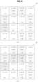
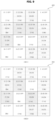
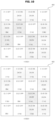
- FIGS. 6 to 11 are diagrams referenced for describing an operation of the air conditioner according to an embodiment of the present disclosure.
- a cooling target temperature for each region may be displayed at a left side and the indoor temperature may be displayed at a right side.
- powers of a second indoor unit IDU12, a third indoor unit IDU13, a fifth indoor unit IDU21, an eighth indoor unit IDU21, a twelfth indoor unit IDU34, a fifteenth indoor unit IDU43, and a sixteenth indoor unit IDU44 may be on.
- the second indoor unit IDU12, the third indoor unit IDU13, the fifth indoor unit IDU21, and the fifteenth indoor unit IDU43 among the indoor units IDU of which powers are on may be the indoor units IDU requiring the operation support.
- the fifth indoor unit IDU21 in which the difference between the target temperature and the indoor temperature is the largest as 4°C among the indoor units IDU requiring the operation support may be determined as the target indoor unit.
- the air conditioner may determine a ninth indoor unit IDU31 having a largest capacity as 13k BTU, as the support indoor unit for the fifth indoor unit IDU21.
- the air conditioner may additionally determine the target indoor unit among the indoor units IDU requiring the operation support.
- the third indoor unit IDU13 in which the difference between the target temperature and the indoor temperature is the largest as 3°C may be determined as the target indoor unit.
- the air conditioner may add the support indoor unit for the fifth indoor unit IDU21.
- the air conditioner since the first indoor unit IDU11 and the sixth indoor unit IDU22 have the same capacity, and regions adjacent to the sixth indoor unit IDU22 are more than those of the first indoor unit IDU11, the air conditioner may add the sixth indoor unit IDU22 as the support indoor unit for the fifth indoor unit IDU21.
- the air conditioner may determine the seventh indoor unit IDU23 as the support indoor unit for the third indoor unit IDU13.
- the air conditioner may additionally determine the fifteenth indoor unit IDU43 among the indoor units IDU requiring the operation support as the target indoor unit.
- the third indoor unit IDU13 may be excluded from the target indoor unit. Further, as the third indoor unit IDU13 is removed from the target indoor unit, the power of the seventh indoor unit IDU23 which is the support indoor unit for the third indoor unit IDU13 may be off.
- the air conditioner may maintain the number of support indoor units for the fifth indoor unit IDU21.
- the air conditioner may determine the eleventh indoor unit IDU33 as the support indoor unit for the fifteenth unit IDU13.
- the air conditioner may skip the addition of the target indoor unit because all of the indoor units IDU requiring the operation support are set to the target state.
- the fifth indoor unit IDU21 may be excluded from the target indoor unit. Further, as the fifth indoor unit IDU21 is removed from the target indoor unit, the powers of the sixth indoor unit IDU22 and the ninth indoor unit IDU31 which are the support indoor units for the fifth indoor unit IDU23 may be off.
- the air conditioner may maintain the number of support indoor units for the fifteenth indoor unit IDU43.
- the indoor temperature of the predetermined region may quickly reach the target temperature through the support operation of the indoor unit IDU adjacent to the predetermined region.
- the optimal indoor unit IDU may be determined, which is to be used for the operation assistance for the predetermined region.
- an air conditioner may include: an outdoor unit; a plurality of indoor units disposed to correspond to a plurality of regions, respectively; temperature sensors sensing indoor temperatures for the plurality of regions corresponding to the plurality of indoor units, respectively; and a controller, and the controller may set, when there is at least one first indoor unit in which an indoor temperature of a corresponding region is lower than a target temperature among the plurality of indoor units, any one of the first indoor units to a second indoor unit requiring an operation support, based on a difference between the target temperature and the indoor temperature, set any one of indoor units which are adjacent to the second indoor unit, and of which powers are off to a third indoor unit that supports an operation of the second indoor unit, and control the operation by turning on a power of the third indoor unit.
- the controller may determine a fourth indoor unit in which the difference between the target temperature and the indoor temperature is the largest to the second indoor unit among the plurality of first indoor units.
- the controller may determine, as the second indoor unit, an indoor unit having the smallest number of indoor units in operation therearound among the plurality of fourth indoor units.
- the controller may perform a cooling operation, and determines, when there are a plurality of fourth indoor units, as the second indoor unit, an indoor unit in which the target temperature is the lowest among the plurality of fourth indoor units, and performs a heating operation, and determine, when there are a plurality of fourth indoor units, as the second indoor unit, an indoor unit in which the target temperature is the highest among the plurality of fourth indoor units.
- the controller may determine, as the third indoor unit, a fifth indoor unit having a largest capacity among the plurality of indoor units which are adjacent to the second indoor unit, and of which powers are off.
- the controller may determine, as the third indoor unit, an indoor unit having the largest number of indoor units in operation therearound among the plurality of fifth indoor units.
- the controller may determine, as the third indoor unit, an indoor unit having the largest number of adjacent regions among the plurality of fifth indoor units.
- a target temperature of the third indoor unit may be lower than the target temperature of the second indoor unit corresponding thereto during a cooling operation, and the target temperature of the third indoor unit may be higher than the target temperature of the second indoor unit corresponding thereto during a heating operation.
- the controller may control an operation of the third indoor unit during a predetermined control cycle, determine a change degree of an indoor temperature of a region corresponding to the second indoor unit for the control cycle when the control cycle elapses, and set any one of indoor units which are adjacent to the second indoor unit, and of which powers are off to a sixth indoor unit that additionally supports the operation of the second indoor unit when the change degree is less than a predetermined reference.
- the controller may release the setting for the second indoor unit when an indoor temperature of a predetermined region corresponding to the second indoor unit reaches the target temperature of the second indoor unit, and turn off a power of the third indoor unit.
- an operating method of the present disclosure may be implemented as a processor readable code in a processor readable recording medium.
- the processor readable recording medium includes all kinds of recording devices storing data which may be deciphered by a processor. Examples of the processor readable recording medium include a ROM, a RAM, a CD-ROM, a magnetic tape, a floppy disk, an optical data storage device, and the like and further include a device implemented as a type of a carrier wave such as transmission through the Internet. Further, the processor readable recording media may be stored and executed as codes which may be distributed in the computer system connected through a network and read by the processor in a distribution method.
Landscapes
- Engineering & Computer Science (AREA)
- Signal Processing (AREA)
- Chemical & Material Sciences (AREA)
- Combustion & Propulsion (AREA)
- Mechanical Engineering (AREA)
- General Engineering & Computer Science (AREA)
- Physics & Mathematics (AREA)
- Fuzzy Systems (AREA)
- Mathematical Physics (AREA)
- Human Computer Interaction (AREA)
- Air Conditioning Control Device (AREA)
Applications Claiming Priority (1)
| Application Number | Priority Date | Filing Date | Title |
|---|---|---|---|
| KR1020230130112A KR20250046548A (ko) | 2023-09-27 | 2023-09-27 | 공기조화기 |
Publications (1)
| Publication Number | Publication Date |
|---|---|
| EP4530550A1 true EP4530550A1 (de) | 2025-04-02 |
Family
ID=92909510
Family Applications (1)
| Application Number | Title | Priority Date | Filing Date |
|---|---|---|---|
| EP24202405.7A Pending EP4530550A1 (de) | 2023-09-27 | 2024-09-25 | Klimaanlage |
Country Status (4)
| Country | Link |
|---|---|
| US (1) | US20250102178A1 (de) |
| EP (1) | EP4530550A1 (de) |
| KR (1) | KR20250046548A (de) |
| CN (1) | CN119713514A (de) |
Citations (4)
| Publication number | Priority date | Publication date | Assignee | Title |
|---|---|---|---|---|
| JP2014149117A (ja) * | 2013-01-31 | 2014-08-21 | Fujitsu General Ltd | 空気調和機 |
| EP3370004A1 (de) * | 2016-01-06 | 2018-09-05 | Samsung Electronics Co., Ltd. | Automatisches temperaturregelungsverfahren und vorrichtung |
| WO2020224037A1 (zh) * | 2019-05-07 | 2020-11-12 | 珠海格力电器股份有限公司 | 多联机空调系统的控制方法及装置 |
| US11306934B2 (en) * | 2017-08-30 | 2022-04-19 | Mitsubishi Electric Corporation | Air-conditioning system control apparatus using degree of influence between air-conditioning indoor units |
-
2023
- 2023-09-27 KR KR1020230130112A patent/KR20250046548A/ko active Pending
-
2024
- 2024-09-23 CN CN202411324255.3A patent/CN119713514A/zh active Pending
- 2024-09-25 EP EP24202405.7A patent/EP4530550A1/de active Pending
- 2024-09-26 US US18/897,417 patent/US20250102178A1/en active Pending
Patent Citations (4)
| Publication number | Priority date | Publication date | Assignee | Title |
|---|---|---|---|---|
| JP2014149117A (ja) * | 2013-01-31 | 2014-08-21 | Fujitsu General Ltd | 空気調和機 |
| EP3370004A1 (de) * | 2016-01-06 | 2018-09-05 | Samsung Electronics Co., Ltd. | Automatisches temperaturregelungsverfahren und vorrichtung |
| US11306934B2 (en) * | 2017-08-30 | 2022-04-19 | Mitsubishi Electric Corporation | Air-conditioning system control apparatus using degree of influence between air-conditioning indoor units |
| WO2020224037A1 (zh) * | 2019-05-07 | 2020-11-12 | 珠海格力电器股份有限公司 | 多联机空调系统的控制方法及装置 |
Also Published As
| Publication number | Publication date |
|---|---|
| US20250102178A1 (en) | 2025-03-27 |
| CN119713514A (zh) | 2025-03-28 |
| KR20250046548A (ko) | 2025-04-03 |
Similar Documents
| Publication | Publication Date | Title |
|---|---|---|
| EP2620718B1 (de) | Vorrichtung und verfahren zur luftkühlung und heisswasserzufuhr | |
| CN102770718B (zh) | 空调系统及空调系统的控制方法 | |
| CN103597290B (zh) | 温度调节系统、空调系统 | |
| EP3882524A1 (de) | Klimatisierungssystem | |
| JPWO2016071947A1 (ja) | 冷凍サイクル装置及び冷凍サイクル装置の異常検知システム | |
| CN105953369B (zh) | 一种变频空调控制方法及装置 | |
| US20190353374A1 (en) | Air conditioner system and control method thereof | |
| US11300302B2 (en) | Air conditioner system, air conditioner control device, air conditioner method, and program for control using water circulation and based on indoor latent and sensible heat loads | |
| KR20150057624A (ko) | 공기 조화기 및 그 제어방법 | |
| JP2012037159A (ja) | 空気調和機の制御装置および冷凍装置の制御装置 | |
| KR20210093666A (ko) | 공기조화기 및 그 제어방법 | |
| KR20150125343A (ko) | 공기조화기 및 그 제어방법 | |
| EP4163562A1 (de) | Klimaanlage und betriebsverfahren dafür | |
| US20230408129A1 (en) | Air conditioner | |
| CN113465224A (zh) | 热泵及其动作方法 | |
| JPH1194327A (ja) | 空気調和機の制御装置 | |
| EP4530550A1 (de) | Klimaanlage | |
| AU2015364901A1 (en) | Air conditioning apparatus | |
| EP4530548A1 (de) | Klimaanlage | |
| KR20230050103A (ko) | 공기조화기 및 그 동작방법 | |
| CN214370579U (zh) | 空调器系统 | |
| US11573025B2 (en) | Server and control method thereof for a multi-air conditioning system including grouping of indoor units | |
| KR102104446B1 (ko) | 공기조화기 및 그 동작 방법 | |
| KR102080844B1 (ko) | 멀티형 공기 조화기 및 그의 배관탐색방법 | |
| CN114543299A (zh) | 用于空调器的控制方法及空调器 |
Legal Events
| Date | Code | Title | Description |
|---|---|---|---|
| PUAI | Public reference made under article 153(3) epc to a published international application that has entered the european phase |
Free format text: ORIGINAL CODE: 0009012 |
|
| STAA | Information on the status of an ep patent application or granted ep patent |
Free format text: STATUS: REQUEST FOR EXAMINATION WAS MADE |
|
| 17P | Request for examination filed |
Effective date: 20240925 |
|
| AK | Designated contracting states |
Kind code of ref document: A1 Designated state(s): AL AT BE BG CH CY CZ DE DK EE ES FI FR GB GR HR HU IE IS IT LI LT LU LV MC ME MK MT NL NO PL PT RO RS SE SI SK SM TR |