EP4530608A1 - Ensemble capteur, machine agricole et procédé associé - Google Patents
Ensemble capteur, machine agricole et procédé associé Download PDFInfo
- Publication number
- EP4530608A1 EP4530608A1 EP24194002.2A EP24194002A EP4530608A1 EP 4530608 A1 EP4530608 A1 EP 4530608A1 EP 24194002 A EP24194002 A EP 24194002A EP 4530608 A1 EP4530608 A1 EP 4530608A1
- Authority
- EP
- European Patent Office
- Prior art keywords
- sample
- sensor
- measuring chamber
- inlet
- sensor assembly
- Prior art date
- Legal status (The legal status is an assumption and is not a legal conclusion. Google has not performed a legal analysis and makes no representation as to the accuracy of the status listed.)
- Pending
Links
Images
Classifications
-
- G—PHYSICS
- G01—MEASURING; TESTING
- G01N—INVESTIGATING OR ANALYSING MATERIALS BY DETERMINING THEIR CHEMICAL OR PHYSICAL PROPERTIES
- G01N21/00—Investigating or analysing materials by the use of optical means, i.e. using sub-millimetre waves, infrared, visible or ultraviolet light
- G01N21/84—Systems specially adapted for particular applications
- G01N21/85—Investigating moving fluids or granular solids
-
- A—HUMAN NECESSITIES
- A01—AGRICULTURE; FORESTRY; ANIMAL HUSBANDRY; HUNTING; TRAPPING; FISHING
- A01D—HARVESTING; MOWING
- A01D41/00—Combines, i.e. harvesters or mowers combined with threshing devices
- A01D41/12—Details of combines
- A01D41/127—Control or measuring arrangements specially adapted for combines
- A01D41/1277—Control or measuring arrangements specially adapted for combines for measuring grain quality
-
- G—PHYSICS
- G01—MEASURING; TESTING
- G01N—INVESTIGATING OR ANALYSING MATERIALS BY DETERMINING THEIR CHEMICAL OR PHYSICAL PROPERTIES
- G01N21/00—Investigating or analysing materials by the use of optical means, i.e. using sub-millimetre waves, infrared, visible or ultraviolet light
- G01N21/17—Systems in which incident light is modified in accordance with the properties of the material investigated
- G01N21/25—Colour; Spectral properties, i.e. comparison of effect of material on the light at two or more different wavelengths or wavelength bands
- G01N21/31—Investigating relative effect of material at wavelengths characteristic of specific elements or molecules, e.g. atomic absorption spectrometry
- G01N21/35—Investigating relative effect of material at wavelengths characteristic of specific elements or molecules, e.g. atomic absorption spectrometry using infrared light
- G01N21/3563—Investigating relative effect of material at wavelengths characteristic of specific elements or molecules, e.g. atomic absorption spectrometry using infrared light for analysing solids; Preparation of samples therefor
-
- G—PHYSICS
- G01—MEASURING; TESTING
- G01N—INVESTIGATING OR ANALYSING MATERIALS BY DETERMINING THEIR CHEMICAL OR PHYSICAL PROPERTIES
- G01N21/00—Investigating or analysing materials by the use of optical means, i.e. using sub-millimetre waves, infrared, visible or ultraviolet light
- G01N21/17—Systems in which incident light is modified in accordance with the properties of the material investigated
- G01N21/25—Colour; Spectral properties, i.e. comparison of effect of material on the light at two or more different wavelengths or wavelength bands
- G01N21/31—Investigating relative effect of material at wavelengths characteristic of specific elements or molecules, e.g. atomic absorption spectrometry
- G01N21/35—Investigating relative effect of material at wavelengths characteristic of specific elements or molecules, e.g. atomic absorption spectrometry using infrared light
- G01N21/359—Investigating relative effect of material at wavelengths characteristic of specific elements or molecules, e.g. atomic absorption spectrometry using infrared light using near infrared light
-
- G—PHYSICS
- G01—MEASURING; TESTING
- G01N—INVESTIGATING OR ANALYSING MATERIALS BY DETERMINING THEIR CHEMICAL OR PHYSICAL PROPERTIES
- G01N21/00—Investigating or analysing materials by the use of optical means, i.e. using sub-millimetre waves, infrared, visible or ultraviolet light
- G01N21/84—Systems specially adapted for particular applications
-
- G—PHYSICS
- G01—MEASURING; TESTING
- G01N—INVESTIGATING OR ANALYSING MATERIALS BY DETERMINING THEIR CHEMICAL OR PHYSICAL PROPERTIES
- G01N21/00—Investigating or analysing materials by the use of optical means, i.e. using sub-millimetre waves, infrared, visible or ultraviolet light
- G01N21/84—Systems specially adapted for particular applications
- G01N2021/8466—Investigation of vegetal material, e.g. leaves, plants, fruits
-
- G—PHYSICS
- G01—MEASURING; TESTING
- G01N—INVESTIGATING OR ANALYSING MATERIALS BY DETERMINING THEIR CHEMICAL OR PHYSICAL PROPERTIES
- G01N21/00—Investigating or analysing materials by the use of optical means, i.e. using sub-millimetre waves, infrared, visible or ultraviolet light
- G01N21/84—Systems specially adapted for particular applications
- G01N21/85—Investigating moving fluids or granular solids
- G01N2021/8592—Grain or other flowing solid samples
Definitions
- the present invention relates to a sensor assembly according to the preamble of claim 1, an agricultural machine equipped therewith and a corresponding method.
- Other harvesting machines such as balers or forage harvesters, are also equipped with sensors to record crop properties, either to map these properties at a specific location for precision agriculture purposes or to allow the operator to adjust crop processing parameters based on the measured crop properties either automatically or based on a display of the crop properties.
- sensors are also used on other agricultural machines, e.g., on seed drills to record the properties of the seed being sown or on slurry tankers to record the nutrient content of the slurry being spread.
- the sensors are arranged adjacent to a channel along which the material flows during operation (as in EP 1 523 874 A1 or US 2022/0132736 A1 ), or they are attached to a branch line to which a portion of the material is fed, and capture flowing or standing material (see, for example, WO 2006/010761 A1 , US 6 285 198 B1 , US 2002/0133309 A1 , EP 0 908 086 A1 , DE 10 2010 062 417 A1 ).
- the sensors are often detachably mounted on the agricultural machine and can also be used to examine other materials, for example by attaching them to a different mount, i.e. by being used as a stationary sensor (EP 1 523 874 A1 ) or can be positioned on a conveyor belt on which the crop is transported past them, or can be manually immersed into a tank containing crop ( US 2002/0039186 A1 ).
- a sensor assembly comprises a sensor configured to detect at least one property of a sample, and a measuring chamber having an inlet through which the sample can be introduced into the measuring chamber.
- the sensor is configured to interact with the sample contained in the measuring chamber and determine its property.
- the inlet is connectable to a line through which material conveyed in an agricultural machine can be guided as a sample through the inlet into the measuring chamber.
- the line is detachable from the inlet of the measuring chamber, and a filling device for filling a (different) sample can be coupled to the inlet instead of the line.
- the sensor assembly to the agricultural machine permanently or detachably in order to introduce, in a manner known per se, material conveyed in the machine through a line and an inlet into a measuring chamber of the sensor assembly in a first (normal) measuring mode, in which the material is examined by the sensor, but to make the sensor assembly reconfigurable when attached to the machine in such a way that the line is separated from the inlet and, instead of the line, a filling device is coupled to the inlet in order to (different) measuring mode, a sample other than the material currently being conveyed by the agricultural machine can be fed into the measuring chamber and examined there with the sensor.
- the line can be manually removed from a fastening at the inlet and replaced with the filling device, although it would also be conceivable to install a valve at the inlet or in the line that can be adjusted manually or by means of an actuator, through which the inlet can be connected either to the line that is supplied with the material from the machine, or to the filling device, which can be permanently or detachably attached to the valve.
- the filling device can be manually filled by an operator and may, for example, comprise a hopper. The operator can then feed the material to be tested through the filling device into the sensor assembly.
- the operator can use a container (bucket or similar) to take a sample from a crop container, e.g., the grain tank of a combine harvester or a loading hopper containing crops picked up and chopped by a forage harvester, or any other container or storage facility, and empty the container into the filling device to test the crop using the sensor assembly.
- the measuring chamber can comprise a first outlet through which the material fed through the line can be fed back to the agricultural machine, and a second outlet through which a (different) sample fed into the measuring chamber by means of the filling device can be led out of the measuring chamber. Accordingly, the (different) sample is not returned to the machine through the first outlet, but is led into the second outlet.
- This second outlet can be connectable to a container for receiving the sample drained from the measuring chamber.
- the second outlet is arranged at the bottom of the measuring chamber upstream of the first outlet and can be closed, be it by a plug or lid or a movable closure.
- the measuring chamber is preferably assigned a conveyor which is configured to convey the sample along the sensitive surface of the sensor.
- This makes it possible to use the sensor not only to create a single measured value of the sample, but also to record a larger number of measured values at different points of the sample which is gradually passed by the sensor (either by moving the sample step by step in order to be able to record the area of the sample detected by the sensor with a longer measuring time, or by moving the sample continuously past the sensor and the sensor taking measurements at a predetermined frequency, e.g. 1 Hz) in order to reduce measurement errors.
- a predetermined frequency e.g. 1 Hz
- the conveyor is arranged downstream of the sensitive surface of the sensor, particularly with regard to the flow direction of the sample.
- the sensor may be a near-infrared spectrometer, although any other sensors, such as cameras, capacitive humidity meters, and the like, may also be used as a sensor.
- the sensor assembly may comprise a single such sensor or a combination of two or more different sensors mentioned in this paragraph.
- An agricultural machine in particular a harvesting machine, can be equipped with a described sensor assembly.
- the machine comprises means for conveying agricultural material, wherein the sensor assembly is configured to receive material conveyed through the line in the machine and present it to the sensor as a sample so that the sensor can detect the property of the material. Accordingly, in the normal, first measuring mode, a portion of the material moving in a conveyor channel in the agricultural machine (branched off from the conveyor channel) or the entire material flowing in the conveyor channel (which then corresponds to the line) is conveyed through the line into the sensor assembly.
- a method for measuring properties of harvested material or another sample by means of a sensor assembly comprising a sensor configured to detect at least one property of a sample and a measuring chamber having an inlet for the sample, provides that in a first measuring mode the inlet is connected to a line through which material conveyed in an agricultural machine is guided as a sample through the inlet and into the measuring chamber and the sensor interacts with the sample contained in the measuring chamber and determines its property, while in a second measuring mode the line is separated from the inlet of the measuring chamber and instead of the line a filling device for filling in a sample (other than that coming from the machine) is coupled to the inlet.
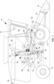
- FIG. 1 in which, as an example of an agricultural machine, a harvesting machine in the form of a combine harvester 10 is shown, which comprises a main frame 12 with driven front and steerable rear, ground-engaging wheels 14 which support the main frame 12 for forward movement across a field to be harvested.
- wheels 14 are shown, the combine harvester 10 may be supported wholly or partially on ground-engaging crawler tracks.
- the drive to the front wheels 14 is provided by a conventional hydrostatic transmission from an internal combustion engine attached to the main frame 12.
- directional references (such as forward) refer to the forward direction of the combine harvester 10, which in the Figure 1 runs to the right.
- a height-adjustable header in the form of a cutting unit 16 is used to harvest crop and feed it to a feederhouse 18.
- the feederhouse 18 is pivotally mounted on the main frame 12 and includes a conveyor for feeding the incoming crop to a guide drum 20.
- the guide drum 20 conveys the crop upward through an inlet transition section 22 to a rotating threshing and separating assembly 24.
- Other orientations and types of threshing structures and other types of headers 16 may also be used, such as a transversely extending frame supporting individual row units.
- the rotating threshing and separating assembly 24 threshes and separates the crop. Grain and chaff fall through grates at the bottom of the rotating threshing and separating assembly 24 into a cleaning system 26.
- the cleaning system 26 comprises a Blower 28, upper sieves 30, and lower sieves 32 separate the chaff.
- the clean grain is gathered across the width of the cleaning system 26 by a cross-feed auger 34, which feeds it to a clean grain elevator 36.
- the elevator 36 comprises chains and paddles and conveys the clean grain into a transition section 38, from which it is conveyed into a grain tank 42 by a grain tank filling auger 40.
- the elevator 36 has an upward conveying run (arrow 52) and a downward (empty) run (arrow 54).
- the clean grain in the grain tank 42 can be transferred to a grain cart or truck by an unloading auger 44.
- Tailings are returned from the rear end of the lower sieve 32 to the rotating threshing and separating assembly 24 by a tailings elevator 54.
- Threshed, separated straw is transferred from the rotating threshing and separating assembly 24 through an outlet 46 to a discharge conveyor 48.
- the discharge conveyor 48 discharges the straw out the rear of the combine harvester 10. It should be noted that the discharge conveyor 48 could feed the non-grain material directly to a straw chopper.
- the operation of the combine harvester 10 is controlled from an operator's cab 50.
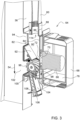
- the sensor assembly 64 comprises a sensor 66, which is mounted within a housing 68.
- the sensor 66 is, in particular, a near-infrared spectrometer that looks into a measuring chamber 72 through a window 70 in the housing.
- the sensor 66 designed as a near-infrared spectrometer, comprises, in a manner known per se, a light source with which the measuring chamber 72 is exposed to light in the infrared range, as well as light-sensitive elements that receive light reflected from a sample contained in the measuring chamber 72, split according to wavelength.
- a computer device 76 can determine the proportions of certain ingredients in the sample.
- the computer device 76 can be contained in the housing 68 or be separate from it.
- a fiber optic cable could be mounted between the sample and the light-sensitive elements.
- a suitable sensor 66 itself is for example in the EP 4 184 148 A1 shown and described.
- the computer device 76 is connected to a controller 80 with a processor 78, which in turn is connected to a display device 74 and transmits the respectively detected ingredient contents of the sample.
- the ingredients of the grain detected by the sensor 66 can be displayed on the display device 74, stored in a georeferenced manner by the processor 78, and/or used by the controller 80 to automatically control operating parameters of the combine harvester 10. For example, the adjustment of a threshing gap can be dependent on the moisture content of the grain detected by the sensor 66 in order to avoid unnecessary breakage when the grain is dry.
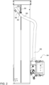
- the measuring chamber 72 is located within a support assembly 82, which in turn is attached to the side wall of the elevator 36.
- the support assembly 82 comprises a hollow housing 84 equipped with an upper nozzle 86 to which the line 60 is removably attached by means of a union nut 88. Below the nozzle 86, the housing 84 of the support assembly 82 forms a chamber 90.
- the wall 92 of the chamber 90 opposite the sensor 66 is inclined downwards and towards the sensor 66, so that the chamber 90 narrows downwards in a funnel shape and forms the measuring chamber 72 at the lower end of the wall 92.
- the sensor 66 detects the properties or contents of a sample contained in the measuring chamber 72.
- the lower end of the nozzle 86 can be regarded in the sense of the claims as the inlet 114 of the support assembly 82 and thus also of the measuring chamber 72.
- the support assembly 82 is provided with an opening 94 which overlaps with an opening in the side wall of the elevator 36.
- the conveyor 96 which in the embodiment shown is equipped with drivers distributed around its circumference, which are here helical, and is drivable by a drive (not shown) about an axis running horizontally and parallel to the side wall of the elevator 36.
- the undershot conveyor 96 is arranged downstream of the measuring chamber 72 and, when rotated by the drive, conveys the grain out of the measuring chamber 72, so that new grain is fed in from above. slides down and the conveyor 96 as a result conveys the grain or sample through the measuring chamber 72 and along the sensor 66, so that different grains are gradually examined by the sensor 66.
- the bottom 98 of the support assembly 82 forms a trough below the conveyor 96 adapted to the envelope of the conveyor 96.
- the conveyor 96 when driven, conveys the grain from the measuring chamber 72 along the bottom 98 and through a first outlet 102 back to the downwardly running run of the elevator 36.
- the first outlet 102 is formed by corresponding openings in the support assembly 82 and in the side wall of the elevator 36.
- the bottom 98 also includes, upstream of the first outlet 102 below the conveyor 96, a second outlet 100, which merges downwards into a nozzle 104.
- the second outlet 100 and the nozzle 104 are closed by a plug 106 (which is flush with the adjacent base 98), which is inserted into the nozzle 104 and locked there by a pin 108.
- the cross sections of the nozzle 104 and the plug 106, which fits exactly into it, are rectangular here.
- the previously described structure of the sensor assembly 64 makes it possible, in a first measuring mode, to guide grain from the upwardly moving section of the elevator 36 via the line 60 into the measuring chamber 72, examine it there (as a sample) with the sensor 66, convey it out of the measuring chamber 72 with the conveyor 96, and guide the grain through the first opening back into the downwardly moving section of the elevator 36.
- the sample flows continuously past the sensor 66, and measurements are taken at a predetermined frequency.
- the measured values can be georeferenced and mapped in a conventional manner, in particular by compensating for the travel time of the crop from its original location in the field until it reaches the sensor.
- Such a sensor assembly 64 is (apart from the second outlet 100, the nozzle 104 and the plug 106) in the US patent application 18/312841 and 18/312905 dated 5 May 2023, the contents of which are incorporated into the present documents by reference.
- Other similar sensor assemblies are also disclosed in the Figures 2 and 4 the US 2002/0133309 A1 shown, the entire disclosure of which is also incorporated by reference into these documents.
- a second measuring mode is also possible with the sensor assembly shown.
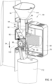
- the line 60 is disconnected from the upper nozzle 86 (by an operator of the combine harvester 10 manually, in particular without tools by unscrewing the union nut 88 and pulling the flexible line 66 from the nozzle 86). removed and, in its place, a filling device 110 in the form of a funnel is placed on the upper nozzle 86.
- the cylindrical outlet of the filling device 110 extends into the chamber 90.
- the plug 106 is removed from the nozzle 104 and a container 112 is placed or otherwise fixed (suspended or the like) below the nozzle 104.
- an operator can therefore fill grain (of any origin, e.g., from the grain tank 42 or another container in which, for example, grain is stored) into the filling device 110 when the combine harvester 10 is stationary but the sensor 66 and the drive of the conveyor 96 are electrically supplied.
- the conveyor 96 then conveys the grain from the chamber 90 into the measuring chamber 72 and it is examined (as a sample) by the sensor 66 and finally passes through the second outlet 100 and the nozzle 104 into the container 112.
- the measured values associated with a single total sample filled into the filling device 110 are usually averaged and displayed and/or stored to the operator, e.g., on the sensor assembly or the display device 74.
- the sensor 66 and the conveyor 96 can be continuously in operation or can be activated upon operator input via a suitable interface (particularly on the sensor assembly, e.g., in the form of a (push-button) switch, possibly with an operating mode display) or remote control.
- the sensor arrangement 64 is thus configured to examine a (different) sample in a second measuring mode, which sample does not pass through the line 60, but rather from the filling device 110 into the measuring chamber 72, where it is examined by the sensor 66.
- This (different) sample is not returned to the returning run of the elevator 36, but is guided into the container 112.
- Another possibility is to open the second outlet 100 (with the combine harvester 10 and conveyor 96 stationary) and position a container 112 underneath it, while the line 66 is connected to the nozzle 86, and then to activate the conveyor 96 for a limited time in order to remove the grain sensed by the sensor 66 from the combine harvester 10 as a reference sample and to examine it in a laboratory for calibration purposes. Automatic sampling could also be provided for this purpose, see FIG. DE 10 2010 062 417 A1 , and the second opening 100 can be opened and closed by an actuator-operated closure.
Landscapes
- Physics & Mathematics (AREA)
- Spectroscopy & Molecular Physics (AREA)
- Life Sciences & Earth Sciences (AREA)
- General Health & Medical Sciences (AREA)
- Analytical Chemistry (AREA)
- Biochemistry (AREA)
- Chemical & Material Sciences (AREA)
- General Physics & Mathematics (AREA)
- Immunology (AREA)
- Pathology (AREA)
- Health & Medical Sciences (AREA)
- Environmental Sciences (AREA)
- Investigating Or Analysing Materials By Optical Means (AREA)
Applications Claiming Priority (1)
| Application Number | Priority Date | Filing Date | Title |
|---|---|---|---|
| DE102023126147.9A DE102023126147A1 (de) | 2023-09-26 | 2023-09-26 | Sensorzusammenbau, landwirtschaftliche Maschine und zugehöriges Verfahren |
Publications (1)
| Publication Number | Publication Date |
|---|---|
| EP4530608A1 true EP4530608A1 (fr) | 2025-04-02 |
Family
ID=92302436
Family Applications (1)
| Application Number | Title | Priority Date | Filing Date |
|---|---|---|---|
| EP24194002.2A Pending EP4530608A1 (fr) | 2023-09-26 | 2024-08-12 | Ensemble capteur, machine agricole et procédé associé |
Country Status (4)
| Country | Link |
|---|---|
| US (1) | US20250102430A1 (fr) |
| EP (1) | EP4530608A1 (fr) |
| AU (1) | AU2024216286A1 (fr) |
| DE (1) | DE102023126147A1 (fr) |
Citations (11)
| Publication number | Priority date | Publication date | Assignee | Title |
|---|---|---|---|---|
| EP0908086A1 (fr) | 1997-10-09 | 1999-04-14 | CLAAS Selbstfahrende Erntemaschinen GmbH | Dispositif de mesure de l'humidité de grain dans des machines de récolte |
| US6285198B1 (en) | 1995-09-01 | 2001-09-04 | Deere & Company | Grain moisture sensor |
| WO2001069213A2 (fr) | 2000-03-10 | 2001-09-20 | Textron Systems Corporation | Sondes optiques et procedes d'analyse spectrale |
| US20020133309A1 (en) | 2000-07-19 | 2002-09-19 | Hardt Ivan E. | Yield monitoring system for grain harvesting combine |
| US6559655B1 (en) * | 2001-04-30 | 2003-05-06 | Zeltex, Inc. | System and method for analyzing agricultural products on harvesting equipment |
| EP1523874A1 (fr) | 2003-10-15 | 2005-04-20 | Deere & Company | Dispositif de mesure des substances contenues dans des récoltes |
| WO2006010761A1 (fr) | 2004-07-28 | 2006-02-02 | Cnh Belgium Nv | Appareil et procede servant a analyser la composition d'une recolte dans une machine a transporter la recolte |
| DE102010062417A1 (de) | 2009-12-11 | 2011-06-16 | Deere & Company, Moline | Erntegutprobenpräsentationssystem |
| US20220132736A1 (en) | 2020-11-03 | 2022-05-05 | Deere & Company | Kernel-level grain monitoring systems for combine harvesters |
| EP4184148A1 (fr) | 2021-11-18 | 2023-05-24 | Deere & Company | Agencement de capteurs |
| US20230296506A1 (en) * | 2022-03-18 | 2023-09-21 | Topcon Corporation | Granular-substance component measuring method and granular-substance component measuring instrument |
Family Cites Families (10)
| Publication number | Priority date | Publication date | Assignee | Title |
|---|---|---|---|---|
| US6845326B1 (en) * | 1999-11-08 | 2005-01-18 | Ndsu Research Foundation | Optical sensor for analyzing a stream of an agricultural product to determine its constituents |
| DE102008043377A1 (de) * | 2008-10-31 | 2010-05-06 | Deere & Company, Moline | Messanordnung zur spektroskopischen Untersuchung und Durchsatzerfassung eines Erntegutstroms |
| US10318138B2 (en) * | 2011-03-11 | 2019-06-11 | Intelligent Agricultural Solutions Llc | Harvesting machine capable of automatic adjustment |
| US9629308B2 (en) * | 2011-03-11 | 2017-04-25 | Intelligent Agricultural Solutions, Llc | Harvesting machine capable of automatic adjustment |
| DE102015215299A1 (de) * | 2015-08-11 | 2017-02-16 | Deere & Company | Messeinrichtung zur Untersuchung geernteten Korns in einem Mähdrescher |
| US10172285B2 (en) * | 2015-10-23 | 2019-01-08 | Carnegie Mellon University | System for evaluating agricultural material |
| AU2017382800B2 (en) * | 2016-12-19 | 2022-08-04 | Climate Llc | Systems, methods and apparatus for soil and seed monitoring |
| DE102017214352A1 (de) * | 2017-08-17 | 2019-02-21 | Deere & Company | Spektrometrischer Messkopf für forst-, land- und lebensmittelwirtschaftliche Anwendungen |
| DE102020205708A1 (de) * | 2020-05-06 | 2021-11-11 | Deere & Company | Sensoranordnung |
| US11832550B2 (en) * | 2020-11-03 | 2023-12-05 | Deere & Company | Agricultural nutrient application using real-time spectroscopic analysis of live crop |
-
2023
- 2023-09-26 DE DE102023126147.9A patent/DE102023126147A1/de active Pending
-
2024
- 2024-08-12 EP EP24194002.2A patent/EP4530608A1/fr active Pending
- 2024-08-23 AU AU2024216286A patent/AU2024216286A1/en active Pending
- 2024-09-12 US US18/882,842 patent/US20250102430A1/en active Pending
Patent Citations (12)
| Publication number | Priority date | Publication date | Assignee | Title |
|---|---|---|---|---|
| US6285198B1 (en) | 1995-09-01 | 2001-09-04 | Deere & Company | Grain moisture sensor |
| EP0908086A1 (fr) | 1997-10-09 | 1999-04-14 | CLAAS Selbstfahrende Erntemaschinen GmbH | Dispositif de mesure de l'humidité de grain dans des machines de récolte |
| WO2001069213A2 (fr) | 2000-03-10 | 2001-09-20 | Textron Systems Corporation | Sondes optiques et procedes d'analyse spectrale |
| US20020039186A1 (en) | 2000-03-10 | 2002-04-04 | Rosenberg Charles W. Von | Optical probes and methods for spectral analysis |
| US20020133309A1 (en) | 2000-07-19 | 2002-09-19 | Hardt Ivan E. | Yield monitoring system for grain harvesting combine |
| US6559655B1 (en) * | 2001-04-30 | 2003-05-06 | Zeltex, Inc. | System and method for analyzing agricultural products on harvesting equipment |
| EP1523874A1 (fr) | 2003-10-15 | 2005-04-20 | Deere & Company | Dispositif de mesure des substances contenues dans des récoltes |
| WO2006010761A1 (fr) | 2004-07-28 | 2006-02-02 | Cnh Belgium Nv | Appareil et procede servant a analyser la composition d'une recolte dans une machine a transporter la recolte |
| DE102010062417A1 (de) | 2009-12-11 | 2011-06-16 | Deere & Company, Moline | Erntegutprobenpräsentationssystem |
| US20220132736A1 (en) | 2020-11-03 | 2022-05-05 | Deere & Company | Kernel-level grain monitoring systems for combine harvesters |
| EP4184148A1 (fr) | 2021-11-18 | 2023-05-24 | Deere & Company | Agencement de capteurs |
| US20230296506A1 (en) * | 2022-03-18 | 2023-09-21 | Topcon Corporation | Granular-substance component measuring method and granular-substance component measuring instrument |
Also Published As
| Publication number | Publication date |
|---|---|
| US20250102430A1 (en) | 2025-03-27 |
| DE102023126147A1 (de) | 2025-03-27 |
| AU2024216286A1 (en) | 2025-04-10 |
Similar Documents
| Publication | Publication Date | Title |
|---|---|---|
| DE102010062417B4 (de) | Erntegutprobenpräsentationssystem | |
| EP2401906B1 (fr) | Dispositif de détection et de détermination de la composition de matières en vrac | |
| EP1053671B2 (fr) | Dispositif de mesure des substances contenues dans et/ou des propriétés des récoltes | |
| EP1523874B1 (fr) | Dispositif de mesure des substances contenues dans des récoltes | |
| EP2517549B1 (fr) | Agencement et procédé de détection de la quantité de plantes sur un champ | |
| DE102004038404B4 (de) | Einrichtung zur selbsttätigen Einstellung der Schnitthöhe eines Erntevorsatzes zur Ernte stängelartiger Pflanzen | |
| EP2845461B1 (fr) | Agencement de mesure de perte dans une moissonneuse-batteuse | |
| EP3130213B1 (fr) | Dispositif de mesure destiné à analyser des grains récoltés dans une moissonneuse-batteuse | |
| EP3444577B1 (fr) | Tête de mesure spectrométrique pour applications forestières, agricoles et alimentaires | |
| DE102008043377A1 (de) | Messanordnung zur spektroskopischen Untersuchung und Durchsatzerfassung eines Erntegutstroms | |
| DE102005043991A1 (de) | Verfahren zur Einstellung eines Arbeitsaggregats einer Erntemaschine | |
| EP2761984A1 (fr) | Capteur d'oscillations | |
| EP1038429A1 (fr) | Dispositif pour mesurer la quantité des grains dans le dispositif de renvoi de résidus d'une moissonneuse-batteuse | |
| EP2168419B1 (fr) | Moissonneuse agricole | |
| DE102016217169B4 (de) | Elevatorpaddel-Design zum Optimieren der Entnahme von Stichproben im Nebenstrom | |
| DE102015212107B4 (de) | Vorrichtung und Verfahren zur kontinuierlichen Bestimmung des Sandgehaltes von Futterpflanzen während des Ernteprozesses | |
| DE10230475A1 (de) | Vorrichtung zur Entnahme von Proben | |
| DE102022110185A1 (de) | Verfahren und Anordnung zur Messung einer kornspezifischen Größe an einer Erntemaschine | |
| DE102023126147A1 (de) | Sensorzusammenbau, landwirtschaftliche Maschine und zugehöriges Verfahren | |
| DE19647433A1 (de) | Verfahren und Vorrichtung zum Hanfdrusch mit Schleppergeräten | |
| DE19523026A1 (de) | Verfahren und Vorrichtung zur Messung eines Massestromes | |
| DE102021110556A1 (de) | Mähdrescher sowie Verfahren zum Betreiben eines Mähdreschers | |
| EP4368969A1 (fr) | Procédé et dispositif pour déterminer une taille spécifique à la masse et/ou à la taille de céréales | |
| DE102024118178A1 (de) | Sensoranordnung zur Erfassung von Körnern in einem Körner und Nichtkornbestandteile enthaltenden Materialstrom in einem Mähdrescher | |
| WO2026104725A1 (fr) | Système de fauchage agricole |
Legal Events
| Date | Code | Title | Description |
|---|---|---|---|
| PUAI | Public reference made under article 153(3) epc to a published international application that has entered the european phase |
Free format text: ORIGINAL CODE: 0009012 |
|
| STAA | Information on the status of an ep patent application or granted ep patent |
Free format text: STATUS: THE APPLICATION HAS BEEN PUBLISHED |
|
| AK | Designated contracting states |
Kind code of ref document: A1 Designated state(s): AL AT BE BG CH CY CZ DE DK EE ES FI FR GB GR HR HU IE IS IT LI LT LU LV MC ME MK MT NL NO PL PT RO RS SE SI SK SM TR |
|
| STAA | Information on the status of an ep patent application or granted ep patent |
Free format text: STATUS: REQUEST FOR EXAMINATION WAS MADE |
|
| 17P | Request for examination filed |
Effective date: 20251002 |