EP4530612A1 - Dispositif de détection de vis - Google Patents
Dispositif de détection de vis Download PDFInfo
- Publication number
- EP4530612A1 EP4530612A1 EP23200702.1A EP23200702A EP4530612A1 EP 4530612 A1 EP4530612 A1 EP 4530612A1 EP 23200702 A EP23200702 A EP 23200702A EP 4530612 A1 EP4530612 A1 EP 4530612A1
- Authority
- EP
- European Patent Office
- Prior art keywords
- rail
- guide
- assembly
- screw
- visual
- Prior art date
- Legal status (The legal status is an assumption and is not a legal conclusion. Google has not performed a legal analysis and makes no representation as to the accuracy of the status listed.)
- Withdrawn
Links
Images







Classifications
-
- G—PHYSICS
- G01—MEASURING; TESTING
- G01N—INVESTIGATING OR ANALYSING MATERIALS BY DETERMINING THEIR CHEMICAL OR PHYSICAL PROPERTIES
- G01N21/00—Investigating or analysing materials by the use of optical means, i.e. using sub-millimetre waves, infrared, visible or ultraviolet light
- G01N21/84—Systems specially adapted for particular applications
- G01N21/88—Investigating the presence of flaws or contamination
- G01N21/95—Investigating the presence of flaws or contamination characterised by the material or shape of the object to be examined
- G01N21/952—Inspecting the exterior surface of cylindrical bodies or wires
-
- G—PHYSICS
- G01—MEASURING; TESTING
- G01N—INVESTIGATING OR ANALYSING MATERIALS BY DETERMINING THEIR CHEMICAL OR PHYSICAL PROPERTIES
- G01N21/00—Investigating or analysing materials by the use of optical means, i.e. using sub-millimetre waves, infrared, visible or ultraviolet light
- G01N21/84—Systems specially adapted for particular applications
- G01N21/88—Investigating the presence of flaws or contamination
- G01N21/8851—Scan or image signal processing specially adapted therefor, e.g. for scan signal adjustment, for detecting different kinds of defects, for compensating for structures, markings, edges
-
- G—PHYSICS
- G01—MEASURING; TESTING
- G01N—INVESTIGATING OR ANALYSING MATERIALS BY DETERMINING THEIR CHEMICAL OR PHYSICAL PROPERTIES
- G01N21/00—Investigating or analysing materials by the use of optical means, i.e. using sub-millimetre waves, infrared, visible or ultraviolet light
- G01N21/84—Systems specially adapted for particular applications
- G01N2021/845—Objects on a conveyor
Definitions
- the present invention relates to a device configured to detect screws, especially to a device with a linear carrying rail, which is used to carry screws, and automatically controlling and adjusting mechanisms through a controlling module to detect screws of different sizes.
- the screw detection device comprises multiple detection cameras and a rotary disk.
- the rotary disk has multiple detection recesses.
- the multiple detection cameras are disposed around and face the rotary disk to photograph.
- the screw detection device rotates the rotary disk.
- a screw-feeding device feeds multiple screws to the rotary disk and puts each of the screws into a respective one of the multiple detection recesses.
- the screw detection device rotates the rotary disk to move the screws to pass through the front of the multiple detection cameras. By the multiple detection cameras photographing each screw, the screw detection device detects and determines whether said screw is defective.
- a screw factory often produces screws of different sizes.
- detection recesses in a rotary disk also have different sizes. So, to detect screws of different sizes, the rotary disk in the screw detection device needs to be changed. This is less convenient, and also the multiple detection cameras of the screw detection device have to be refocused, and changing the rotary disk and refocusing the multiple detection cameras are manually operated.
- manual adjustments are prone to errors, hence increasing the detection error rate and product defect rate, and therefore it is hard to tell whether a defective product is caused by errors of a detection device or by errors of production, and therefore improvements are still needed.
- the main objective of the present invention is to provide a screw detection device to resolve drawbacks that a detection device nowadays needs to change rotary disks and refocus detection cameras manually, hence being inconvenient, increasing a detection error rate and a product defect rate, and causes of a defective product are hard to tell.
- the screw detection device comprises a device base, a carrying mechanism, a top visual-detection mechanism and a lateral visual-detection mechanism.
- the device base has an installing plate and a controlling module mounted inside the device base.
- the device base comprises a classifying assembly mounted on the installing plate.
- the controlling module is electrically connected to the classifying assembly.
- the carrying mechanism is mounted on the installing plate and comprises a carrying rail, a space-adjusting assembly and a conveyance assembly.
- the carrying rail has two guide-rail assemblies extending along a linear direction and arranged parallelly.
- the space-adjusting assembly is connected to the two guide-rail assemblies and drives the two guide-rail assemblies toward or away from each other.
- the conveyance assembly cooperates with the carrying rail to move a screw on the two guide-rail assemblies along the linear direction toward the classifying assembly.
- the controlling module is electrically connected to and controls the space-adjusting assembly and the conveyance assembly.
- the top visual-detection mechanism is mounted on the installing plate and comprises a top visual-detection camera and a top focal-length-controlling assembly.
- the top visual-detection camera is disposed over the carrying rail and faces toward the carrying rail.
- the top focal-length-controlling assembly is connected to the top visual-detection camera, is electrically connected to and controlled by the controlling module, and can adjust a focal length of the top visual-detection camera.
- the controlling module is electrically connected to the top visual-detection camera and the lateral visual-detection camera and controls the top visual-detection camera and the lateral visual-detection camera to photograph the screw, so that the controlling module determines whether the screw is defective and discards a defective screw through the classifying assembly.
- the screw detection device is configured to detect screws.
- a screw-feeding device feeds several screws onto the two guide-rail assemblies of the carrying rail of the carrying mechanism and lets the screws extend to be between the two guide-rail assemblies.
- the conveyance assembly drives the screws moving forward along the linear direction.
- each one of the screws is photographed.
- the controlling module of the screw detection device detects and determines whether the screw is defective, and discards a defective screw through the classifying assembly.
- the screw detection device has the following advantages:
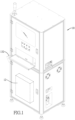
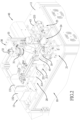
- a screw detection device in accordance with the present invention comprises a device base 10, a carrying mechanism 20, a top visual-detection mechanism 30 and a lateral visual-detection mechanism 40.
- the device base 10 has an installing plate 11 and a controlling module 12, which is mounted inside the device base 10.
- the device base 10 comprises a classifying assembly 13 mounted on the installing plate 11.
- the controlling module 12 is electrically connected to the classifying assembly 13.
- the carrying mechanism 20 is mounted on the installing plate 11 and comprises a carrying rail 21, a space-adjusting assembly 22 and a conveyance assembly 23.
- the carrying rail 21 has two guide-rail assemblies 211 extending along a linear direction and arranged parallelly.
- the space-adjusting assembly 22 is connected to the two guide-rail assemblies 211 and drives the two guide-rail assemblies 211 toward or away from each other.
- the conveyance assembly 23 cooperates with the carrying rail 21 to move a screw 50 on the two guide-rail assemblies 211 along the linear direction toward the classifying assembly 13.
- the controlling module 12 is electrically connected to and controls the space-adjusting assembly 22 and the conveyance assembly 23.
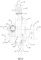
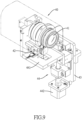
- the top visual-detection mechanism 30 is mounted on the installing plate 11 and comprises a top visual-detection camera 31 and a top focal-length-controlling assembly 32.
- the top visual-detection camera 31 is disposed over the carrying rail 21 and faces toward the carrying rail 21.
- the top focal-length-controlling assembly 32 is connected to the top visual-detection camera 31, is electrically connected to and controlled by the controlling module 12, and can adjust a focal length of the top visual-detection camera 31.
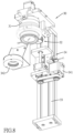
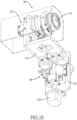
- the lateral visual-detection mechanism 40 is mounted on the installing plate 11 and comprises a lateral visual-detection camera 41 and a lateral focal-length-controlling assembly 42.
- the lateral visual-detection camera 41 is disposed at a side of the carrying rail 21 and faces toward the carrying rail 21.
- the lateral focal-length-controlling assembly 42 is connected to the lateral visual-detection camera 41, is electrically connected to and controlled by the controlling module 12, and can adjust a focal length of the lateral visual-detection camera 41.
- controlling module 12 is electrically connected to the top visual-detection camera 31 and the lateral visual-detection camera 41 and controls the top visual-detection camera 31 and the lateral visual-detection camera 41 to photograph the screw 50, so that the controlling module 12 determines whether the screw 50 is defective and discards a defective screw through the classifying assembly 13.
- the screw detection device is configured to detect screws 50.
- a screw-feeding device feeds several screws 50 onto the two guide-rail assemblies 211 of the carrying rail 21 of the carrying mechanism 20 and lets the screws 50 extend to be between the two guide-rail assemblies 211.
- the conveyance assembly 23 drives the screws 50 to move forward along the linear direction.
- each one of the screws 50 is photographed.
- the controlling module 12 of the screw detection device detects and determines whether a screw 50 is defective.
- two ends of the carrying rail 21 are respectively defined as a feeding end 212 and a discharging end 213.
- the carrying rail 21 has a detecting area defined between the feeding end 212 and the discharging end 213.
- the screw 50 is fed into the carrying rail 21 through the feeding end 212 and is discharged from the discharging end 213.
- the classifying assembly 13 is adjacent to the discharging end 213.
- the top visual-detection camera 31 and the lateral visual-detection camera 41 respectively face toward the detecting area of the carrying rail 21.
- the conveyance assembly 23 comprises a conveyance driving set 231 and two conveyance belts 232.
- the conveyance driving set 231 comprises a conveyance driving element 233, a conveyance link component 234 and two driving wheels 235.
- the conveyance driving element 233 is mounted at the installing plate 11 and is electrically connected to and controlled by the controlling module 12.
- the conveyance driving element 233 is connected to the conveyance link component 234.
- the two driving wheels 235 are connected to the conveyance link component 234 and respectively correspond to the two guide-rail assemblies 211.
- the two conveyance belts 232 are respectively mounted around the two driving wheels 235 and the two guide-rail assemblies 211.
- the conveyance driving set 231 drives the two conveyance belts 232 to operate.
- the conveyance driving element 233 is preferably a motor.
- each one of the two guide-rail assemblies 211 comprises a guide-rail seat 214 and a guide-rail element 215.
- the guide-rail element 215 is mounted on the guide-rail seat 214.
- Each one of the two driving wheels 235 is mounted on the guide-rail seat 214 of the corresponding guide-rail assembly 211.
- Each one of the two conveyance belts 232 is mounted around the guide-rail element 215 of the corresponding guide-rail assembly 211.
- Each one of the two guide-rail assemblies 211 comprises multiple position-limited pieces 216 and multiple guiding wheels 217.
- the multiple position-limited pieces 216 are mounted at the guide-rail element 215 of said guide-rail assembly 211 to limit the conveyance belt 232 corresponding to the said guide-rail assembly 211 in position.
- the multiple guiding wheels 217 are adjustably mounted at the guide-rail seat 214 and are disposed at two ends of the guide-rail element 215 of said guide-rail assembly 211.
- Each one of the two conveyance belts 232 is mounted around the multiple guiding wheels 217 of the corresponding guide-rail assembly 211.
- the multiple guiding wheels 217 abut the corresponding conveyance belt 232.
- the carrying mechanism 20 comprises a pressing assembly 24 disposed at the feeding end 212 of the carrying mechanism 20.
- the pressing assembly 24 comprises a pressing seat 241, a pressing arm 242 and an elastic element 243.
- the pressing seat 241 is mounted at the carrying rail 21.
- One end of the pressing arm 242 is swing-ably mounted at the pressing seat 241, and another end of the pressing arm 242 is disposed over the two guide-rail assemblies 211 and has a pressing wheel 244.
- the elastic element 243 is mounted between and abuts the pressing seat 241 and the pressing arm 242.
- the screw head of the screw 50 is carried on the two conveyance belts 232 and a thread segment of the screw 50 is in a space between the two guide-rail elements 215.
- the controlling module 12 controls the conveyance driving element 233 of the conveyance driving set 231 of the conveyance assembly 23 to operate.
- the conveyance link component 234 driving the two driving wheels 235 to rotate, the two driving wheels 235 respectively move the conveyance belts 232 on the two corresponding guide-rail assemblies 211, so the screw 50 is moved from the feeding end 212 of the carrying rail 21 toward the discharging end 213 along the linear direction.
- the top visual-detection camera 31 photographs the screw 50 to take a photograph of the screw head of the screw 50.
- the lateral visual-detection camera 41 photographs the screw 50 to take a photograph of the thread segment of the screw 50. Then the top visual-detection camera 31 and the lateral visual-detection camera 41 respectively transmit photographic data to the controlling module 12 for the controlling module 12 to determine whether the screw 50 is defective.
- the classifying assembly 13 comprises a first discharging slideway 131, a second discharging slideway 132 and an air-spraying classifying element 133.
- the first discharging slideway 131 and the second discharging slideway 132 are adjacent to a tail end of the carrying rail 21.
- the first discharging slideway 131 corresponds to the tail end of the carrying rail 21 in position.
- the second discharging slideway 132 is adjacent to the first discharging slideway 131.
- the air-spraying classifying element 133 is adjacent to the tail end of the carrying rail 21 and is connected to an external air source.
- the controlling module 12 is electrically connected to and controls the air-spraying classifying element 133.
- the tail end of the carrying rail 21 is the discharging end 213 of the carrying rail 21.
- the controlling module 12 determines that the screw 50 is a normal screw without any defect, then when the normal screw is moved to the discharging end 213 of the carrying rail 21, the controlling module 12 controls the air-spraying classifying element 133 to spray air, pushing the normal screw to leave the carrying rail 21 and fall into the second discharging slideway 132. If the controlling module 12 determines that the screw 50 is a defective screw, then when the defective screw is moved to the discharging end 213 of the carrying rail 21, the defective screw leaves the carrying rail 21, and falls into the first discharging slideway 131, thereby classifying the screws 50 into the normal screw and the defective screw.
- a conventional screw detection device uses a rotary disk to carry to-be-detected screws, so the screw-feeding device feeds the to-be-detected screws onto the rotating rotary disk.
- a rotational speed of the rotary disk is limited.
- the conveyance assembly 23 of the carrying mechanism 20 moves screws 50 on the two guide-rail assemblies 211 along the linear direction to process detection. So, compared to the conventional screw detection device, the screw detection device in accordance with the present invention does not need to consider the effect of centrifugal device, and hence a feeding speed of the screw-feeding device can be increased, thereby increasing a detection amount.
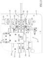
- the space-adjusting assembly 22 is mounted at a bottom side of the installing plate 11 and comprises at least one space-adjusting slide rail 221, an adjusting driving element 222, an adjusting driven component 223 and two connecting bars 224.
- the at least one space-adjusting slide rail 221 is mounted on the installing plate 11 and is perpendicular to the linear direction.
- the guide-rail seats 214 of the two guide-rail assemblies 211 are linearly movable on the at least one space-adjusting slide rail 221.
- the adjusting driven component 223 is connected between the adjusting driving element 222 and the two connecting bars 224.
- the two connecting bars 224 pass through the installing plate 11 and are respectively connected to the guide-rail seats 214 of the two guide-rail assemblies 211.
- the adjusting driving element 222 is electrically connected to and controlled by the controlling module 12.
- the adjusting driving element 222 drives the adjusting driven component 223 to move the two connecting bars 224, thereby moving the two guide-rail assemblies 211 toward and away from each other to adjust the space between the two guide-rail elements 215 to correspond to the screws 50 of different sizes.
- the adjusting driving element 222 is preferably a motor.
- the space-adjusting assembly 22 comprises a manually-adjusting element 225 connected to the adjusting driven component 223. Operating the manually-adjusting element 225 can manually adjust the two guide-rail elements 215.
- the top visual-detection mechanism 30 comprises a top base seat 33, a top fill-light assembly 34 and a top back-light plate 35.
- the top base seat 33 is vertically mounted on the installing plate 11.
- the top visual-detection camera 31, the top focal-length-controlling assembly 32 and the top fill-light assembly 34 are mounted at the top base seat 33.
- the top fill-light assembly 34 comprises a top fill-light driving component 341 and a top fill-light element 342.
- the top fill-light driving component 341 is electrically connected to and controlled by the controlling module 12, and connects to and moves the top fill-light element 342 up and down.
- the top fill-light element 342 is disposed between the top visual-detection camera 31 and the two guide-rail assemblies 211 of the carrying rail 21.
- the top back-light plate 35 is mounted at the carrying rail 21, is disposed below the two guide-rail assemblies 211, and corresponds to the top visual-detection camera 31 in position.
- the lateral visual-detection mechanism 40 comprises a lateral base seat 43, a lateral camera-driving assembly 44 and a lateral back-light plate 45.
- the lateral base seat 43 is vertically mounted on the installing plate 11.
- the lateral camera-driving assembly 44 comprises a lateral camera pedestal 441 and a pedestal-driving element 442.
- the lateral camera pedestal 441 is up-and-down moveably mounted at the lateral base seat 43.
- the pedestal-driving element 442 is mounted at the lateral base seat 43 and is electrically connected to and controlled by the controlling module 12 to move the lateral camera pedestal 441.
- the lateral visual-detection camera 41 and the lateral focal-length-controlling assembly 42 are respectively mounted on the lateral camera pedestal 441.
- the lateral back-light plate 45 corresponds to the lateral visual-detection camera 41 in position.
- the lateral back-light plate 45 and the lateral visual-detection camera 41 are respectively disposed at two sides of the two guide-rail assemblies 211.
- the pedestal-driving element 442 is preferably a motor.
- top back-light plate 35 is electrically connected to and controlled by the controlling module 12.
- the top fill-light element 342 and the top back-light plate 35 emit light to make the photograph of the screw 50 taken by the top visual-detection camera 31 clearer.
- the lateral back-light plate 45 is electrically connected to and controlled by the controlling module 12, and emits light to make the photograph of the screw 50 taken by the lateral visual-detection camera 41 clearer, thereby increasing detection accuracy.
- the controlling module 12 controls the top focal-length-controlling assembly 32 to adjust the focal length of the top visual-detection camera 31, controls the top fill-light driving component 341 to move the top fill-light element 342 up and down, and controls the lateral focal-length-controlling assembly 42 to adjust the focal length of the lateral visual-detection camera 41.
- the controlling module 12 controls the pedestal-driving element 442 of the lateral camera-driving assembly 44 to move the lateral camera pedestal 441 up and down along the lateral base seat 43, thereby adjusting a height position of the lateral visual-detection camera 41.
- the controlling module 12 When using the screw detection device to detect the screws 50 of different sizes, by presetting the adjusting parameters of the controlling module 12, the controlling module 12 automatically controls the carrying rail 21, the top visual-detection camera 31 and the lateral visual-detection camera 41 to meet detection needs of the screws 50 of different sizes. Therefore, manual adjustments are unnecessary, increasing convenience and reducing time spent on operations, and effectively reducing errors caused by adjusting device, hence increasing detection accuracy, and it is easier for manufacturers to determine whether a defective product is caused by errors of production.
- the distance between the two guide-rail assemblies 211 can be adjusted through the space-adjusting assembly 22, so the carrying rail 21 can correspond to the screws 50 of different sizes, and rotary disks of different sizes are unnecessary, thereby lowering the costs.
- the controlling module 12 inside the device base 10 of said screw detection device records the adjusting parameters of the screws of the particular size. Then, the adjusting parameters can be provided to the controlling module 12 of another screw detection device for use. Therefore, different screw detection devices can share the adjusting parameters, so repeating detecting and recording is unnecessary, increasing convenience of use.
- the screw detection device is configured to detect the screws 50 of different sizes.
- the controlling module 12 automatically controls the carrying rail 21, the top visual-detection camera 31 and the lateral visual-detection camera 41 to meet the detection needs of screws 50 of different sizes, and therefore manual adjustments are unnecessary. And by the linear carrying rail 21, the detection amount is increased.
Landscapes
- Chemical & Material Sciences (AREA)
- Pathology (AREA)
- Analytical Chemistry (AREA)
- Physics & Mathematics (AREA)
- Health & Medical Sciences (AREA)
- Life Sciences & Earth Sciences (AREA)
- Biochemistry (AREA)
- Immunology (AREA)
- General Physics & Mathematics (AREA)
- General Health & Medical Sciences (AREA)
- Computer Vision & Pattern Recognition (AREA)
- Engineering & Computer Science (AREA)
- Signal Processing (AREA)
- Sorting Of Articles (AREA)
Priority Applications (1)
| Application Number | Priority Date | Filing Date | Title |
|---|---|---|---|
| EP23200702.1A EP4530612A1 (fr) | 2023-09-29 | 2023-09-29 | Dispositif de détection de vis |
Applications Claiming Priority (1)
| Application Number | Priority Date | Filing Date | Title |
|---|---|---|---|
| EP23200702.1A EP4530612A1 (fr) | 2023-09-29 | 2023-09-29 | Dispositif de détection de vis |
Publications (1)
| Publication Number | Publication Date |
|---|---|
| EP4530612A1 true EP4530612A1 (fr) | 2025-04-02 |
Family
ID=88315789
Family Applications (1)
| Application Number | Title | Priority Date | Filing Date |
|---|---|---|---|
| EP23200702.1A Withdrawn EP4530612A1 (fr) | 2023-09-29 | 2023-09-29 | Dispositif de détection de vis |
Country Status (1)
| Country | Link |
|---|---|
| EP (1) | EP4530612A1 (fr) |
Cited By (1)
| Publication number | Priority date | Publication date | Assignee | Title |
|---|---|---|---|---|
| CN121113773A (zh) * | 2025-11-14 | 2025-12-12 | 中建新科建设发展有限公司 | 一种建筑用绿色建筑新材料检测装置 |
Citations (8)
| Publication number | Priority date | Publication date | Assignee | Title |
|---|---|---|---|---|
| JPS62239008A (ja) * | 1986-04-11 | 1987-10-19 | Chiyuushiyou Kigyo Jigyodan | 頭付き部品の検査機用搬送装置 |
| JPH0971310A (ja) * | 1995-09-06 | 1997-03-18 | Tokyo Giken Kogyo Kk | 被検査部品搬送機構 |
| US20050257599A1 (en) * | 2004-05-21 | 2005-11-24 | Aerser International Co., Ltd. | Screw detecting machine |
| KR101478824B1 (ko) * | 2013-11-08 | 2015-01-02 | 나사록코팅 주식회사 | 상이한 속도로 이송되는 한쌍의 컨베이어벨트를 가지는 부품선별장치 및 그 운용방법 |
| JP2016102717A (ja) * | 2014-11-28 | 2016-06-02 | 東京技研工業株式会社 | ねじ類の検査方法 |
| CN207929596U (zh) * | 2017-12-18 | 2018-10-02 | 健进制药有限公司 | 灯检机上料轨道 |
| CN213179866U (zh) * | 2020-11-18 | 2021-05-11 | 苏州米基尔自动化设备有限公司 | 一种钢带式ccd检测装置 |
| JP7041200B2 (ja) * | 2020-06-29 | 2022-03-23 | 和通科技股▲フン▼有限公司 | 検品装置 |
-
2023
- 2023-09-29 EP EP23200702.1A patent/EP4530612A1/fr not_active Withdrawn
Patent Citations (8)
| Publication number | Priority date | Publication date | Assignee | Title |
|---|---|---|---|---|
| JPS62239008A (ja) * | 1986-04-11 | 1987-10-19 | Chiyuushiyou Kigyo Jigyodan | 頭付き部品の検査機用搬送装置 |
| JPH0971310A (ja) * | 1995-09-06 | 1997-03-18 | Tokyo Giken Kogyo Kk | 被検査部品搬送機構 |
| US20050257599A1 (en) * | 2004-05-21 | 2005-11-24 | Aerser International Co., Ltd. | Screw detecting machine |
| KR101478824B1 (ko) * | 2013-11-08 | 2015-01-02 | 나사록코팅 주식회사 | 상이한 속도로 이송되는 한쌍의 컨베이어벨트를 가지는 부품선별장치 및 그 운용방법 |
| JP2016102717A (ja) * | 2014-11-28 | 2016-06-02 | 東京技研工業株式会社 | ねじ類の検査方法 |
| CN207929596U (zh) * | 2017-12-18 | 2018-10-02 | 健进制药有限公司 | 灯检机上料轨道 |
| JP7041200B2 (ja) * | 2020-06-29 | 2022-03-23 | 和通科技股▲フン▼有限公司 | 検品装置 |
| CN213179866U (zh) * | 2020-11-18 | 2021-05-11 | 苏州米基尔自动化设备有限公司 | 一种钢带式ccd检测装置 |
Cited By (1)
| Publication number | Priority date | Publication date | Assignee | Title |
|---|---|---|---|---|
| CN121113773A (zh) * | 2025-11-14 | 2025-12-12 | 中建新科建设发展有限公司 | 一种建筑用绿色建筑新材料检测装置 |
Similar Documents
| Publication | Publication Date | Title |
|---|---|---|
| US12350714B2 (en) | Screw detection device | |
| CN1100061A (zh) | 零件排列移送装置 | |
| SE451305B (sv) | Maskin for vinkelstegvis slipning av kanterna pa glasogonlinser | |
| CN109049708B (zh) | 一种3d打印机进料机构 | |
| CN208345372U (zh) | 一种纸板输送机构 | |
| JP2025044321A (ja) | ねじ検出設備 | |
| CN112729097B (zh) | 一种轴承套圈内径检测机 | |
| JP6198314B2 (ja) | ミシン目加工装置 | |
| CN109580616A (zh) | 一种ffc检测切断机 | |
| JPS59160734A (ja) | 光学検査装置 | |
| CN117225738B (zh) | 一种单晶金刚石分选设备及其分选方法 | |
| US10741434B2 (en) | Apparatus for packing ultra-small electronic devices | |
| EP1518807A1 (fr) | Appareil pour accumuler et distribuer des groupes de feuilles | |
| CN117825409A (zh) | 圆柱滚子柱面检测设备 | |
| CN210136180U (zh) | 一种用于影像检查机的小零件上料导正装置 | |
| CN116046792A (zh) | 一种基于在线机器视觉检测的自动定位对焦检测装置 | |
| CN117538258A (zh) | 一种芯片外观检测装置和芯片外观检测设备 | |
| TW202500275A (zh) | 螺絲檢測設備 | |
| CN119658552B (zh) | 一种芯片角磨设备及研磨方法 | |
| CN220548492U (zh) | 修边设备 | |
| CN216880499U (zh) | 一种切离装置及除尘设备 | |
| CN220906340U (zh) | 油石位置校准装置 | |
| CN119703432B (zh) | 一种mlcc陶瓷电容封端质量优化的自动化设备 | |
| CN113318997A (zh) | 视觉检测铆钉设备 | |
| CN222431211U (zh) | 一种用于多线切割设备的张力调整装置 |
Legal Events
| Date | Code | Title | Description |
|---|---|---|---|
| PUAI | Public reference made under article 153(3) epc to a published international application that has entered the european phase |
Free format text: ORIGINAL CODE: 0009012 |
|
| STAA | Information on the status of an ep patent application or granted ep patent |
Free format text: STATUS: REQUEST FOR EXAMINATION WAS MADE |
|
| 17P | Request for examination filed |
Effective date: 20240821 |
|
| AK | Designated contracting states |
Kind code of ref document: A1 Designated state(s): AL AT BE BG CH CY CZ DE DK EE ES FI FR GB GR HR HU IE IS IT LI LT LU LV MC ME MK MT NL NO PL PT RO RS SE SI SK SM TR |
|
| GRAP | Despatch of communication of intention to grant a patent |
Free format text: ORIGINAL CODE: EPIDOSNIGR1 |
|
| STAA | Information on the status of an ep patent application or granted ep patent |
Free format text: STATUS: GRANT OF PATENT IS INTENDED |
|
| INTG | Intention to grant announced |
Effective date: 20250724 |
|
| STAA | Information on the status of an ep patent application or granted ep patent |
Free format text: STATUS: THE APPLICATION IS DEEMED TO BE WITHDRAWN |
|
| 18D | Application deemed to be withdrawn |
Effective date: 20251125 |