EP4530924A1 - Procédé de fonctionnement de plusieurs lecteurs rfid et unité de commande et de surveillance pour lecteurs rfid - Google Patents
Procédé de fonctionnement de plusieurs lecteurs rfid et unité de commande et de surveillance pour lecteurs rfid Download PDFInfo
- Publication number
- EP4530924A1 EP4530924A1 EP23200152.9A EP23200152A EP4530924A1 EP 4530924 A1 EP4530924 A1 EP 4530924A1 EP 23200152 A EP23200152 A EP 23200152A EP 4530924 A1 EP4530924 A1 EP 4530924A1
- Authority
- EP
- European Patent Office
- Prior art keywords
- antennas
- rfid readers
- rfid
- antenna
- time
- Prior art date
- Legal status (The legal status is an assumption and is not a legal conclusion. Google has not performed a legal analysis and makes no representation as to the accuracy of the status listed.)
- Granted
Links
Images

Classifications
-
- G—PHYSICS
- G06—COMPUTING OR CALCULATING; COUNTING
- G06K—GRAPHICAL DATA READING; PRESENTATION OF DATA; RECORD CARRIERS; HANDLING RECORD CARRIERS
- G06K7/00—Methods or arrangements for sensing record carriers, e.g. for reading patterns
- G06K7/10—Methods or arrangements for sensing record carriers, e.g. for reading patterns by electromagnetic radiation, e.g. optical sensing; by corpuscular radiation
- G06K7/10009—Methods or arrangements for sensing record carriers, e.g. for reading patterns by electromagnetic radiation, e.g. optical sensing; by corpuscular radiation sensing by radiation using wavelengths larger than 0.1 mm, e.g. radio-waves or microwaves
- G06K7/10316—Methods or arrangements for sensing record carriers, e.g. for reading patterns by electromagnetic radiation, e.g. optical sensing; by corpuscular radiation sensing by radiation using wavelengths larger than 0.1 mm, e.g. radio-waves or microwaves using at least one antenna particularly designed for interrogating the wireless record carriers
- G06K7/10356—Methods or arrangements for sensing record carriers, e.g. for reading patterns by electromagnetic radiation, e.g. optical sensing; by corpuscular radiation sensing by radiation using wavelengths larger than 0.1 mm, e.g. radio-waves or microwaves using at least one antenna particularly designed for interrogating the wireless record carriers using a plurality of antennas, e.g. configurations including means to resolve interference between the plurality of antennas
-
- H—ELECTRICITY
- H04—ELECTRIC COMMUNICATION TECHNIQUE
- H04L—TRANSMISSION OF DIGITAL INFORMATION, e.g. TELEGRAPHIC COMMUNICATION
- H04L67/00—Network arrangements or protocols for supporting network services or applications
- H04L67/50—Network services
-
- H—ELECTRICITY
- H04—ELECTRIC COMMUNICATION TECHNIQUE
- H04L—TRANSMISSION OF DIGITAL INFORMATION, e.g. TELEGRAPHIC COMMUNICATION
- H04L67/00—Network arrangements or protocols for supporting network services or applications
- H04L67/50—Network services
- H04L67/52—Network services specially adapted for the location of the user terminal
-
- G—PHYSICS
- G06—COMPUTING OR CALCULATING; COUNTING
- G06K—GRAPHICAL DATA READING; PRESENTATION OF DATA; RECORD CARRIERS; HANDLING RECORD CARRIERS
- G06K7/00—Methods or arrangements for sensing record carriers, e.g. for reading patterns
- G06K7/0008—General problems related to the reading of electronic memory record carriers, independent of its reading method, e.g. power transfer
Definitions
- the present invention relates to a method for operating multiple RFID readers, in particular UHF RFID readers, and a control and monitoring unit for RFID readers for carrying out such a method
- Radio transponders can, for example, be RFID tags (radio frequency identification), which are attached to objects to identify or locate them.
- RFID tags contain a memory unit whose content can be read or modified using an RFID reader.
- at least one identifier is stored in each RFID tags.
- RFID readers send out a request signal by generating an alternating electromagnetic field.
- this alternating electromagnetic field can be used to supply power, particularly to passively operated RFID tags that do not have their own power source.
- the alternating electromagnetic field can be modulated by RFID tags to transmit a response signal, for example, through load modulation or varying their antenna impedance.
- Radio transponder systems for industrial automation systems must meet special requirements regarding reliable data transmission, authenticity of transmitted data, and immunity to interference. Since industrial automation systems are used to monitor, control, and regulate technical processes, particularly in the areas of manufacturing, process, and building automation, Disrupted or manipulated radio transponder systems can have serious consequences, in the worst case scenario leading to a standstill of an automation system.
- a method for configuring a communication module of at least one RFID reader is known, which is connected to a communication network via the communication module.
- the at least one RFID reader is connected to the communication module via a serial interface.
- Configuration information comprising at least communication network address information and device type information is stored in a configuration memory unit of the communication module.
- the configuration information stored in the configuration memory unit of the communication module is transmitted to the at least one RFID reader via the serial interface and stored there in a predetermined configuration memory area.
- the configuration information stored in the predetermined configuration memory area of the RFID reader is loaded to configure the replacement communication device when a replacement communication module used instead of the communication module is started up, following a successful validity check.
- a position detection sensor of a position detection system comprising a first and a second radio transponder, each having a transmitting and receiving unit connected to an antenna and a memory unit for persistent data storage.
- the first radio transponder has a power supply source and can be selectively switched to a standby state with reduced energy consumption and to an active operating state with full functionality. In the active operating state, at least one radio connection is established. for position detection to at least one first radio transponder reader.
- the second radio transponder which can be inductively supplied with energy by a radio transponder reader, is designed and configured to switch the first radio transponder from the idle state to the active operating state upon entering a detection range of a second radio transponder reader or to transmit position information assigned to the second radio transponder to a server of the position detection system via the second radio transponder reader.
- UHF RFID systems which operate in the frequency range from 865 MHz to 928 MHz, have a larger coverage area than HF RFID systems, which operate at 13.56 MHz. If multiple RFID readers or multiple RFID reader antennas are located in close proximity to one another, both the positioning and alignment of the antennas must be planned with even greater care to avoid mutual interference, especially during simultaneous reading operations.
- This problem can be solved by synchronizing the reading operations of RFID readers, for example, using a programmable logic controller (PLC) controlling the RFID readers or a master RFID reader.
- PLC programmable logic controller
- synchronization only occurs at the device level, not per antenna. Furthermore, synchronization is only guaranteed as long as the respective programmable logic controller (PLC) or master RFID reader is available without interference.
- RFID readers can generally use the CSMA method to check whether a radio channel is already occupied by other participants before using it. However, this can only detect collisions when accessing a radio channel, not prevent them. An additional check for an existing radio channel occupancy regularly causes performance losses.
- the present invention is therefore based on the object of creating a reliable and high-performance method for operating a plurality of RFID readers, each of which is connected to a plurality of antennas, and of specifying a suitable implementation of the method.
- the RFID readers are time-synchronized via a communications network.
- a time-division multiplexing method in particular Time Division Multiple Access (TDMA)
- TDMA Time Division Multiple Access
- the RFID readers advantageously each comprise a communications module that is synchronized by a time synchronization server provided in the communications network, in particular according to Network Time Protocol (NTP) or Precision Time Protocol (PTP).
- NTP Network Time Protocol
- PTP Precision Time Protocol
- antennas assigned to different RFID readers or to the same RFID reader are identified, the detection ranges of which at least partially overlap.
- a partial overlap of the detection ranges of several antennas occurs in particular when signals from different antennas are received at at least one position. each with a reception field strength above a specified threshold.
- the antennas with at least partially overlapping detection ranges can be identified, for example, during a listen-before-talk operating mode of the antennas or RFID readers.
- the identified antennas with at least partially overlapping detection ranges are marked as conflicting with each other on a graphical user interface of a control and monitoring unit connected to the RFID readers via the communication network.
- a configuration tool for the RFID readers is advantageously provided by the control and monitoring unit.
- At least one cyclically repeating time slot is reserved, which is assigned to the respective antenna.
- the cyclically repeating time slots are reserved for the antennas of the RFID readers, preferably via the control and monitoring unit.
- the time windows are synchronized with time information, in particular NTP or PTP time stamps, within the communication network. Furthermore, the assignment of conflicting antennas to the same time window is blocked. This allows for reliable and high-performance synchronization of the RFID readers and access conflict avoidance at the antenna level.
- the present invention is completely robust against the failure of a previously common programmable logic controller or a master RFID reader used as an alternative for synchronization. For this purpose, redundant time synchronization servers are regularly used in communication networks anyway.
- the antennas of the RFID readers are visualized in a conflict matrix on the graphical user interface of the control and monitoring unit, grouped according to the respective RFID reader. Each antenna is assigned a column and a row within the conflict matrix.
- the conflicting antennas are advantageously highlighted graphically within the conflict matrix. This enables particularly simple and effective monitoring of potential conflicts.
- the assignment of the cyclically repeating time slots to the antennas of the RFID readers is visualized, preferably on the graphical user interface of the control and monitoring unit, grouped by the respective RFID reader in a time slot-antenna matrix.
- Each time slot is assigned a column or row within the time slot-antenna matrix, while each antenna is assigned a row or column within the time slot-antenna matrix.
- Conflicting antennas can thus be graphically highlighted within the time slot-antenna matrix, enabling easy monitoring of critical time slot assignments.
- the control and monitoring unit for RFID readers is intended for carrying out a method according to the preceding embodiments and comprises a graphical user interface.
- the control and monitoring unit configured to detect antennas assigned to different RFID readers or to the same RFID reader whose detection ranges at least partially overlap, and to mark the detected antennas with the at least partially overlapping detection ranges as conflicting with each other on the graphical user interface.
- control and monitoring unit is configured to reserve at least one cyclically repeating time slot for each antenna on the respective RFID reader to use for reading or writing RFID transponders and to assign it to the respective antenna.
- control and monitoring unit is configured to block the assignment of conflicting antennas to the same time slot.
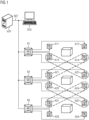
- the arrangement shown comprises several RFID readers R1-R3 interconnected via a communications network NET, each of which has several antennas A11-A14, A21-A24, and A31-A34 connected to it.
- a time-division multiplexing method such as Time Division Multiple Access (TDMA) is used in the communications network NET.
- Each RFID reader R1-R3 includes a communications module that is synchronized by a time synchronization server (NTP) provided in the communications network NET. In this way, the RFID readers are time-synchronized. This can be done, in particular, according to the Network Time Protocol (NTP) or Precision Time Protocol (PTP).
- NTP Network Time Protocol
- PTP Precision Time Protocol
- a control and monitoring unit is provided for the RFID readers R1-R3, which is connected to the RFID readers R1-R3 via the NET communication network.
- the control and monitoring unit provides, in particular, a configuration tool for the RFID readers R1-R3.
- antennas A11-A14, A21-A24, A31-A34 assigned to different RFID readers R1-R3 or to the same RFID reader R1-R3 are identified, whose detection ranges at least partially overlap.
- Such adverse interference is amplified when the RFID readers R1-R3 are UHF RFID readers. Partial overlap of the detection ranges of several antennas occurs particularly when signals from different Antennas A11-A14, A21-A24, A31-A34 are received at at least one position with a reception field strength above a predetermined threshold value.
- the detection ranges of antennas A13 and A22 overlap. Further overlaps exist between antennas A14 and A21, between antennas A23 and A32, and between antennas A24 and A31. Such overlaps can lead to RFID transponders not being correctly read using the affected antennas A13/A22, A14/A21, A23/A32, and A24/A31.
- the antennas A13/A22, A14/A21, A23/A32, A24/A31 with the at least partially overlapping detection ranges can be detected, for example, during a listen-before-talk operating mode of the antennas A11-A14, A21-A24, A31-A34 or the RFID readers R1-R3.
- the identified antennas A13/A22, A14/A21, A23/A32, and A24/A31 with at least partially overlapping detection ranges are identified as conflicting with each other on a graphical user interface of the control and monitoring unit CFG.
- the antennas A11-A14, A21-A24, and A31-A34 of the RFID readers R1-R3 are visualized in a conflict matrix M1 on the graphical user interface of the control and monitoring unit CFG, grouped according to the respective RFID reader R1-R3.
- Each antenna A11-A14, A21-A24, and A31-A34 is assigned a column and a row within the conflict matrix M1.
- the conflicting antennas A13/A22, A14/A21, A23/A32, A24/A31 are graphically highlighted within the conflict matrix M1, for example with a different color or brightness or with additional symbols to indicate overlaps.
- each antenna A11-A14, A21-A24, A31-A34 on the respective RFID reader R1-R3 for reading or writing RFID transponders,
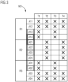
- Figure 3 At least one cyclically repeating time slot T1-T4 is reserved, which is assigned to the respective antenna A11-A14, A21-A24, A31-A34.
- the time slots T1-T4 are synchronized with time information, in particular NTP or PTP time stamps, within the communication network NET. This is preferably done periodically by the RFID readers R1-R3, for example once every several minutes or hours.
- the cyclically repeating time slots T1-T4 are reserved for the antennas A11-A14, A21-A24, A31-A34 of the RFID readers R1-R3 by means of the control and monitoring unit CFG.
- the control and monitoring unit CFG blocks the assignment of the conflicting antennas A13/A22, A14/A21, A23/A32, A24/A31 to the same time slot T1-T4.
- each time window T1-T4 is assigned a column within the time window antenna matrix M2, while each antenna A11-A14, A21-A24, A31-A34 is assigned a row within the time window antenna matrix M2.
- each time slot T1-T4 can be assigned a row within the time slot antenna matrix M2, while each antenna A11-A14, A21-A24, A31-A34 can be assigned a column within the time slot antenna matrix M2.
- the time slot antenna matrix M2 shown shows that the conflicting antennas A13/A22, A14/A21, A23/A32, and A24/A31 are each assigned different time slots T1-T4 due to the blocking described above.
- antenna A13 is assigned time slots T1 and T3, while antenna A22 is assigned complementary time slots T2 and T4.
- antenna A14 is assigned time slots T1 and T3, while antenna A21 is assigned complementary time slots T2 and T4.
- antenna A23 is assigned time slots T2 and T4, while antenna A32 is assigned complementary time slots T1 and T3. Accordingly, time slots T2 and T3 are assigned to antenna A24, while time slots T1 and T4 are assigned to antenna A31.
Landscapes
- Engineering & Computer Science (AREA)
- Computer Networks & Wireless Communication (AREA)
- Signal Processing (AREA)
- Health & Medical Sciences (AREA)
- Toxicology (AREA)
- Physics & Mathematics (AREA)
- Electromagnetism (AREA)
- General Health & Medical Sciences (AREA)
- Artificial Intelligence (AREA)
- Computer Vision & Pattern Recognition (AREA)
- General Physics & Mathematics (AREA)
- Theoretical Computer Science (AREA)
- Mobile Radio Communication Systems (AREA)
Priority Applications (3)
| Application Number | Priority Date | Filing Date | Title |
|---|---|---|---|
| EP23200152.9A EP4530924B1 (fr) | 2023-09-27 | 2023-09-27 | Procédé de fonctionnement de plusieurs lecteurs rfid et unité de commande et de surveillance pour lecteurs rfid |
| PCT/EP2024/074531 WO2025067824A1 (fr) | 2023-09-27 | 2024-09-03 | Procédé de fonctionnement de plusieurs lecteurs rfid, et unité de commande et de surveillance pour lecteurs rfid |
| CN202480062130.XA CN121909469A (zh) | 2023-09-27 | 2024-09-03 | 用于运行多个射频识别读取器的方法和用于射频识别读取器的控制和监视单元 |
Applications Claiming Priority (1)
| Application Number | Priority Date | Filing Date | Title |
|---|---|---|---|
| EP23200152.9A EP4530924B1 (fr) | 2023-09-27 | 2023-09-27 | Procédé de fonctionnement de plusieurs lecteurs rfid et unité de commande et de surveillance pour lecteurs rfid |
Publications (2)
| Publication Number | Publication Date |
|---|---|
| EP4530924A1 true EP4530924A1 (fr) | 2025-04-02 |
| EP4530924B1 EP4530924B1 (fr) | 2026-04-22 |
Family
ID=88207622
Family Applications (1)
| Application Number | Title | Priority Date | Filing Date |
|---|---|---|---|
| EP23200152.9A Active EP4530924B1 (fr) | 2023-09-27 | 2023-09-27 | Procédé de fonctionnement de plusieurs lecteurs rfid et unité de commande et de surveillance pour lecteurs rfid |
Country Status (3)
| Country | Link |
|---|---|
| EP (1) | EP4530924B1 (fr) |
| CN (1) | CN121909469A (fr) |
| WO (1) | WO2025067824A1 (fr) |
Citations (5)
| Publication number | Priority date | Publication date | Assignee | Title |
|---|---|---|---|---|
| US20060022800A1 (en) * | 2004-07-30 | 2006-02-02 | Reva Systems Corporation | Scheduling in an RFID system having a coordinated RFID tag reader array |
| US20090256683A1 (en) * | 2005-10-17 | 2009-10-15 | Reva Systems Corporation | Configuration management system and method for use in an rfid system including a multiplicity of rfid readers |
| US20100176926A1 (en) * | 2007-09-21 | 2010-07-15 | Inha-Industry Partnership Institute | Time slot allocation apparatus and method for preventing collisions between time slots in tdma-based rfid network |
| EP3291488B1 (fr) | 2016-08-30 | 2019-11-20 | Siemens Aktiengesellschaft | Procede de configuration d'un module de communication d'au moins un appareil de lecture rfid et module de communication |
| EP3290948B1 (fr) | 2016-08-31 | 2020-03-25 | Siemens Aktiengesellschaft | Capteur et systeme de determination de position |
-
2023
- 2023-09-27 EP EP23200152.9A patent/EP4530924B1/fr active Active
-
2024
- 2024-09-03 WO PCT/EP2024/074531 patent/WO2025067824A1/fr active Pending
- 2024-09-03 CN CN202480062130.XA patent/CN121909469A/zh active Pending
Patent Citations (5)
| Publication number | Priority date | Publication date | Assignee | Title |
|---|---|---|---|---|
| US20060022800A1 (en) * | 2004-07-30 | 2006-02-02 | Reva Systems Corporation | Scheduling in an RFID system having a coordinated RFID tag reader array |
| US20090256683A1 (en) * | 2005-10-17 | 2009-10-15 | Reva Systems Corporation | Configuration management system and method for use in an rfid system including a multiplicity of rfid readers |
| US20100176926A1 (en) * | 2007-09-21 | 2010-07-15 | Inha-Industry Partnership Institute | Time slot allocation apparatus and method for preventing collisions between time slots in tdma-based rfid network |
| EP3291488B1 (fr) | 2016-08-30 | 2019-11-20 | Siemens Aktiengesellschaft | Procede de configuration d'un module de communication d'au moins un appareil de lecture rfid et module de communication |
| EP3290948B1 (fr) | 2016-08-31 | 2020-03-25 | Siemens Aktiengesellschaft | Capteur et systeme de determination de position |
Also Published As
| Publication number | Publication date |
|---|---|
| CN121909469A (zh) | 2026-04-21 |
| EP4530924B1 (fr) | 2026-04-22 |
| WO2025067824A1 (fr) | 2025-04-03 |
Similar Documents
| Publication | Publication Date | Title |
|---|---|---|
| EP3657424B1 (fr) | Système de communication par intervalles de temps | |
| DE102013207760B4 (de) | Elektrisches Interfacemodul | |
| EP1307395B2 (fr) | Dispositif de surveillance pour ascenseur | |
| DE3424810C2 (fr) | ||
| WO2004001657A1 (fr) | Systeme pour l'echange de donnees entre au moins deux supports de donnees sans contact | |
| EP1508870A1 (fr) | Procédé pour le transfert des données sans fil entre une station de base et un transpondeur | |
| EP1526474B1 (fr) | Procédé pour sélectionner un ou plusieurs transpondeurs | |
| EP2713305B1 (fr) | Procédé et appareil d'écriture/de lecture pour la configuration d'un appareil d'écriture/de lecture dans un agencement RFID | |
| EP2223261B1 (fr) | Réseau rfid et procédé de fonctionnement du réseau rfid | |
| DE102013008516B3 (de) | Transpondereinheit, System und Verfahren zur kontaktlosen Datenübertragung | |
| EP4530924B1 (fr) | Procédé de fonctionnement de plusieurs lecteurs rfid et unité de commande et de surveillance pour lecteurs rfid | |
| DE102014219572A1 (de) | System mit aneinander-reihbaren Elektronikmodulen | |
| EP3599573A1 (fr) | Procédé de transmission de données entre un appareil de lecture transpondeur radio et un transpondeur radio et transpondeur radio | |
| EP3126991B1 (fr) | Module d'interface électrique | |
| EP2560125B1 (fr) | Procédé et appareil d'écriture laser pour un agencement doté d'une multitude de transpondeurs lisibles sans contact | |
| DE60204860T2 (de) | Tdma-übertragungssystem | |
| EP1586917A2 (fr) | Méthode pour faire un choix entre un ou plusieurs répondeurs | |
| DE69803548T2 (de) | Elektronisches Identifizierungssystem für mehrere Transponder | |
| EP1735735B1 (fr) | Procede et dispositif pour reconnaitre des etats fonctionnels dans des systemes rfid et des systemes de teledetection | |
| EP1122684A2 (fr) | Système et procédé d'identification par ondes radio | |
| EP3910529B1 (fr) | Procédé de détection et de suivi locaux des transpondeurs rfid au moyen d'un agencement de lecteur | |
| EP3376430B1 (fr) | Procédé d'attribution d'adresses dans des modules d'un système comportant au moins deux antennes rfid ainsi que dispositif d'antennes de grille comportant au moins deux antennes rfid | |
| EP3282740A1 (fr) | Dispositif de surveillance de bande pour un système de radiocommunication | |
| EP1587022B1 (fr) | Méthode de transmission de données sans fil | |
| DE102008054610A1 (de) | Radiofrequenz-Identifikationssytem zur Vermeidung von Signalkollisionen bei Mehrkanal-Übertragung |
Legal Events
| Date | Code | Title | Description |
|---|---|---|---|
| PUAI | Public reference made under article 153(3) epc to a published international application that has entered the european phase |
Free format text: ORIGINAL CODE: 0009012 |
|
| STAA | Information on the status of an ep patent application or granted ep patent |
Free format text: STATUS: REQUEST FOR EXAMINATION WAS MADE |
|
| 17P | Request for examination filed |
Effective date: 20250103 |
|
| AK | Designated contracting states |
Kind code of ref document: A1 Designated state(s): AL AT BE BG CH CY CZ DE DK EE ES FI FR GB GR HR HU IE IS IT LI LT LU LV MC ME MK MT NL NO PL PT RO RS SE SI SK SM TR |
|
| GRAP | Despatch of communication of intention to grant a patent |
Free format text: ORIGINAL CODE: EPIDOSNIGR1 |
|
| STAA | Information on the status of an ep patent application or granted ep patent |
Free format text: STATUS: GRANT OF PATENT IS INTENDED |
|
| RIC1 | Information provided on ipc code assigned before grant |
Ipc: G06K 7/10 20060101AFI20260116BHEP Ipc: H04L 67/50 20220101ALI20260116BHEP Ipc: H04L 67/52 20220101ALI20260116BHEP Ipc: G06K 7/00 20060101ALN20260116BHEP |
|
| INTG | Intention to grant announced |
Effective date: 20260209 |
|
| GRAS | Grant fee paid |
Free format text: ORIGINAL CODE: EPIDOSNIGR3 |
|
| GRAA | (expected) grant |
Free format text: ORIGINAL CODE: 0009210 |
|
| STAA | Information on the status of an ep patent application or granted ep patent |
Free format text: STATUS: THE PATENT HAS BEEN GRANTED |
|
| AK | Designated contracting states |
Kind code of ref document: B1 Designated state(s): AL AT BE BG CH CY CZ DE DK EE ES FI FR GB GR HR HU IE IS IT LI LT LU LV MC ME MK MT NL NO PL PT RO RS SE SI SK SM TR |
|
| REG | Reference to a national code |
Ref country code: CH Ref legal event code: F10 Free format text: ST27 STATUS EVENT CODE: U-0-0-F10-F00 (AS PROVIDED BY THE NATIONAL OFFICE) Effective date: 20260422 Ref country code: GB Ref legal event code: FG4D Free format text: NOT ENGLISH |