EP4531009A1 - Élément de dispositif de verrouillage destiné à être utilisé dans un procédé d'accès - Google Patents
Élément de dispositif de verrouillage destiné à être utilisé dans un procédé d'accès Download PDFInfo
- Publication number
- EP4531009A1 EP4531009A1 EP23199842.8A EP23199842A EP4531009A1 EP 4531009 A1 EP4531009 A1 EP 4531009A1 EP 23199842 A EP23199842 A EP 23199842A EP 4531009 A1 EP4531009 A1 EP 4531009A1
- Authority
- EP
- European Patent Office
- Prior art keywords
- time
- locking device
- device element
- access
- update
- Prior art date
- Legal status (The legal status is an assumption and is not a legal conclusion. Google has not performed a legal analysis and makes no representation as to the accuracy of the status listed.)
- Pending
Links
Images



Classifications
-
- G—PHYSICS
- G07—CHECKING-DEVICES
- G07C—TIME OR ATTENDANCE REGISTERS; REGISTERING OR INDICATING THE WORKING OF MACHINES; GENERATING RANDOM NUMBERS; VOTING OR LOTTERY APPARATUS; ARRANGEMENTS, SYSTEMS OR APPARATUS FOR CHECKING NOT PROVIDED FOR ELSEWHERE
- G07C9/00—Individual registration on entry or exit
- G07C9/00174—Electronically operated locks; Circuits therefor; Nonmechanical keys therefor, e.g. passive or active electrical keys or other data carriers without mechanical keys
-
- G—PHYSICS
- G07—CHECKING-DEVICES
- G07C—TIME OR ATTENDANCE REGISTERS; REGISTERING OR INDICATING THE WORKING OF MACHINES; GENERATING RANDOM NUMBERS; VOTING OR LOTTERY APPARATUS; ARRANGEMENTS, SYSTEMS OR APPARATUS FOR CHECKING NOT PROVIDED FOR ELSEWHERE
- G07C9/00—Individual registration on entry or exit
- G07C9/00174—Electronically operated locks; Circuits therefor; Nonmechanical keys therefor, e.g. passive or active electrical keys or other data carriers without mechanical keys
- G07C9/00571—Electronically operated locks; Circuits therefor; Nonmechanical keys therefor, e.g. passive or active electrical keys or other data carriers without mechanical keys operated by interacting with a central unit
-
- G—PHYSICS
- G07—CHECKING-DEVICES
- G07C—TIME OR ATTENDANCE REGISTERS; REGISTERING OR INDICATING THE WORKING OF MACHINES; GENERATING RANDOM NUMBERS; VOTING OR LOTTERY APPARATUS; ARRANGEMENTS, SYSTEMS OR APPARATUS FOR CHECKING NOT PROVIDED FOR ELSEWHERE
- G07C9/00—Individual registration on entry or exit
- G07C9/00174—Electronically operated locks; Circuits therefor; Nonmechanical keys therefor, e.g. passive or active electrical keys or other data carriers without mechanical keys
- G07C9/00944—Details of construction or manufacture
-
- G—PHYSICS
- G07—CHECKING-DEVICES
- G07C—TIME OR ATTENDANCE REGISTERS; REGISTERING OR INDICATING THE WORKING OF MACHINES; GENERATING RANDOM NUMBERS; VOTING OR LOTTERY APPARATUS; ARRANGEMENTS, SYSTEMS OR APPARATUS FOR CHECKING NOT PROVIDED FOR ELSEWHERE
- G07C2209/00—Indexing scheme relating to groups G07C9/00 - G07C9/38
- G07C2209/08—With time considerations, e.g. temporary activation, valid time window or time limitations
Definitions
- the invention relates to a locking device element, in particular designed as a key, fitting, or locking cylinder.
- the locking device element is designed for use in an access method. In this access method, access to a physical area is granted or denied.
- the present invention further shows the access method using the locking device element.
- EP 1 899 924 B1 shows a known key for an electromechanical locking cylinder.
- the known key comprises a key blade on which electronics are arranged between two housing shells.
- the object is achieved by the features of the independent claims.
- the dependent claims relate to preferred embodiments of the invention.
- the object is also achieved by a method according to claim 17.
- the method can be carried out using the locking device element according to the invention, in particular the locking device element according to one of claims 1 to 16.
- the locking device element can be designed to carry out the method according to the invention, in particular the method according to claim 16.
- the invention shows a locking device element, which is designed in particular as a key, electromechanical fitting, or locking cylinder.
- the locking device element is designed for use in an access method.
- access method access to a physical area is granted or denied.
- "Granted or denied" means in particular, that access can be both granted and denied, although these two states cannot occur simultaneously. If access is authorized, access is granted. If, on the other hand, access is not authorized, access is denied.
- at least one access condition is checked in an access decision step. Preferably, several access conditions are checked in several access decision steps. Access is authorized if all access decision steps have been decided positively.
- At least one access condition is denied during the access procedure in which at least one access condition, preferably several access conditions, are checked, this results in the entire access being denied.
- This denial of the access condition can, in particular, mean that an access decision is decided negatively in an access decision step of the access procedure.
- At least one access decision step is performed by the locking device element.
- Access to a physical area specifically describes that the access method using the locking device element makes the physical area accessible to a person, allowing the person to enter the physical area and/or at least open the physical area.
- the physical area may also be the interior of a safe or cabinet, into which the person does not enter but gains access by opening a corresponding door.
- access to a physical area may include, for example, opening a door to a room or building, or opening a barrier, turnstile, or turnstile barrier.
- the blocking device element serves to carry out at least one access decision step for granting or denying access to the physical area. It is conceivable that the blocking device element makes the access decision completely or only partially. Alternatively or additionally, the locking device element can provide data for at least one access decision step.
- the locking device element is intended to be carried by a user or located outside the physical area to which access is to be granted or denied. Therefore, attempts to tamper with the locking device element may be made.
- the present invention counteracts such tampering attempts.
- the locking device element is preferably designed as a key comprising a key blade that is inserted into a locking cylinder.
- the key contains electronics.
- the electronics can be used to perform an access decision step and/or to transmit data for an access decision step to the locking cylinder.
- rotation of a driver of the locking cylinder is enabled.
- the locking device element is thus designed as an "electromechanical" key, since in addition to the electronics in the key, mechanical actuation of the locking cylinder—namely, by turning the key—also occurs.
- the locking device element can be designed as an "electronic" key.
- an access decision step can be performed and/or data for an access decision step can be sent to a lock, a locking cylinder, a reader, or a fitting, so that the corresponding access can be granted.
- the locking device element is configured as a fitting, in particular an electromechanical fitting, or a locking cylinder, in particular an electromechanical locking cylinder
- electronics are located in the fitting or the locking cylinder.
- the electronics can preferably perform at least one access decision step.
- a mechanism in the fitting or locking cylinder, controlled by the electronics, can grant or deny access; for example, by releasing the door handle of the fitting or by blocking it, or by engaging or disengaging it. or by unlocking or leaving a cylinder core in the locking cylinder locked, engaging the driver or leaving the driver disengaged.
- the locking device element comprises a first time element.
- This first time element is thus located in the locking device element, for example, in the key.
- the first time element outputs a first time signal.
- This first time signal indicates a first time.
- This first time signal is output by the first time element, in particular continuously or at regular intervals.
- the first time element outputs any signal with a defined frequency.
- This signal or frequency specifies a clock pulse that is counted in another element of the locking device, ultimately resulting in a count value. Before counting, the frequency can preferably be divided.
- the time signal can "indicate the first time” simply by oscillating at a defined frequency.
- the first time element outputs a count value or a value based on the count value (e.g., time) as a time signal and thus as the "first time.”
- the counting of the clock pulse and preferably also the preceding division of the frequency thus takes place in the first time element.
- the count value in the first time element or in another element of the locking device element is interpreted in conjunction with a start value, so that an actual time is ultimately obtained.
- the time can correspond to the first time.
- the locking device element further comprises an electronic processing device.
- the electronic processing device is configured to perform a verification step on information from the first time element, in particular based on the first time.
- the processing device is located in a controller, in particular a microcontroller, of the locking device element. As will be shown in more detail below, the processing device can also perform several of these verification steps.
- the locking device element in particular the electronic processing device, is designed to have at least one further step which depends on the outcome, i.e., the result, of the verification step. If multiple verification steps are performed, the subsequent step may depend on the outcome of these multiple verification steps. Furthermore, it is also possible to perform different subsequent steps based on the multiple verification steps.
- An actual time such as the time of day or a specific day of the week, can determine whether a specific person or group of people should be granted or denied access to the physical area. For example, certain people may be allowed to enter a building during the day on weekdays, whereas a different group of people may do so on weekends or at night.
- an access authorization can only be valid for at least one specific access authorization time window.
- the access authorization time window is particularly recurring, i.e., it encompasses specific time periods between the start and end of the access authorization validity period, such as days or hours within a week.
- the locking device element comprises at least the first time element, so that the verification of the access authorization does not depend, or at least not exclusively, on a time provided elsewhere.
- the first time element arranged in the locking device element allows the time to be determined within the locking device element.
- At least one access decision step performed by the blocking device element is performed using the first time signal, in particular the first (clock) time determined by the time signal.
- the data sent by the blocking device element so that another device performs an access decision step may include the first time signal, in particular the first time.
- the access decision step may include comparing an access authorization time window with the first time. If the first time lies within the access authorization time window, the access decision step is initiated with a positive Result completed. If the first time is outside the access authorization time window, the access decision step is completed with a negative result.
- the first time is compared with an access authorization validity start and/or an access authorization validity end. If the first time is before the access authorization validity start, this access decision step is concluded with a negative result. If the first time is after the access authorization validity start, this access decision step is concluded with a positive result. If the first time is before the access authorization validity end, the corresponding access decision step is concluded with a positive result. If the first time is after the access authorization validity end, the corresponding access decision step is concluded with a negative result.
- several different access decision steps that are carried out using the first time are conceivable.
- the processing device comprises an internal second time element.
- This internal second time element preferably has an internal RC element.
- the internal second time element is preferably designed to generate a second time signal within the processing device.
- the second time signal is generated in the processing device, preferably in the microcontroller.
- the second time signal indicates a second time.
- the second time signal is generated, in particular, continuously or at regular intervals by the second time element.
- the second time element generates any signal with a defined frequency.
- This signal or frequency specifies a clock pulse that is counted in the second time element, i.e., in the processing device, so that Ultimately, a count value is created.
- the frequency can preferably be divided.
- the count value is interpreted in the second time element or in another area of the processing device in conjunction with a start value, so that an actual time is ultimately obtained.
- the second time can correspond to a second time.
- the first timing element is configured and arranged separately from the processing device; thus, it is preferably located outside the microcontroller.
- the blocking device element contains a circuit board on which the first timing element is arranged separately from the microcontroller of the processing device.
- the first timing element is electrically connected to the processing device for transmitting the first time signal, in particular the first time.
- the first time element is a real-time clock (RTC) with an oscillating crystal.
- RTC real-time clock
- the real-time clock comprises, in addition to the oscillating crystal, a frequency divider and a frequency counter.
- the first and second time elements are preferably used in the locking device element. By comparing the times of the two time elements, it can be checked whether one of the two time elements has been manipulated.
- the first and second time elements in the locking device element are particularly preferably positioned at different locations and/or designed differently.
- the first time element is preferably located outside the processing device, i.e. in particular outside the microcontroller.
- the second time element is preferably located inside the processing device, i.e. in particular inside the microcontroller.
- the first time element is preferably a real-time clock, which is much more difficult to manipulate in terms of software than the second time element integrated into the processing device.
- the second time element which is located inside the processing device is significantly more difficult to physically manipulate than the first time element, which is located outside the processing device. The fact that the processing device includes both the second time element and performs the verification step makes manipulation particularly difficult.
- the at least one access decision step performed by the blocking device element is performed by the processing device.
- the same controller that determines the second time is also used to perform the access decision step, in particular an access decision step that depends on a time. This can increase security against manipulation.
- the second time can be used additionally or alternatively.
- the blocking device element can check whether the second time lies within an access authorization time window and/or compare the second time with an access authorization validity start and/or an access authorization validity end.
- the processing device is configured to compare the first time with the second time as a verification step.
- the processing device is configured to compare the first time signal or a value based thereon with the second time signal or a value based thereon.
- the verification step can be performed periodically. Additionally or alternatively, the verification step can be performed during an access procedure.
- the expression "compare the first time with the second time” describes a comparison that determines whether the two times differ from each other. For example, a first time is determined based on the first time and a second time is determined based on the second time, whereby a difference between these two times can be determined. However, such a comparison can also be performed without using actual times. For example, the two times can be counted values of a clock cycle. whereby a comparison of the two times is possible taking into account the starting times and the clock frequencies.
- the locking device element can be configured to deny access to the physical area. This denial is initiated by the locking device element, preferably carried out by the locking device element itself.
- the locking device element can generally initiate the denial of access. This "initiation" includes the locking device element itself denying access. If access is denied, the locking device element can abort the access procedure or terminate it with a negative result, or send a message about the denial to another element that terminates or aborts the access procedure with a negative result. If the locking device element is designed as an electromechanical key, for example, a driver of the locking cylinder cannot rotate if access is denied.
- steps of the access procedure in particular the verification of at least one access condition, take place in another element (for example, in a server, in a cloud, in a connected smartphone, in the locking cylinder, etc.).
- the locking device element can initiate a denial of access by not transmitting corresponding data, in particular the first and/or second time, to this other element; which the other element requires for an access decision step, in particular the first and/or second time.
- the locking device element therefore does not necessarily deny access itself.
- the expression that the blocking device element is designed to initiate, preferably carry out, a denial of access to the physical area refers to all, i.e. future and possibly current, access procedures, at least until a revocation occurs. This means that the use of the blocking device element for all access procedures is denied - at least until a revocation occurs.
- the expression that that the blocking device element is configured to initiate a denial of access to the physical area, preferably to perform this itself may be limited only to the current access procedure, provided that the verification step takes place within the framework of an access procedure.
- the expression that the blocking device element is configured to initiate a denial of access to the physical area may mean generally denying the use of the blocking device element for access procedures for granting access to a physical area or denying current access to the physical area.
- the blocking device element is designed to initiate, preferably itself, a refusal of access to the physical area based on the outcome of the verification step.
- the verification step that leads to the denial includes, in particular, checking whether the first time and the second time differ by more than a stored first time difference. Thus, if the first time deviates too far from the second time, the blocking device element initiates the denial of access to the physical area.
- This verification step can be performed periodically, regardless of whether the blocking device element is currently in an access procedure. Additionally or alternatively, this verification step can be performed in each access procedure.
- the first time and the second time differ by more than a stored first time difference, access can no longer be granted for access procedures by means of the blocking device element - at least until a cancellation has occurred. If the exceeding of the first time difference is detected during a periodic review, access can no longer be granted for all subsequent access procedures - at least until a cancellation has occurred. If the exceeding of the first time difference is detected in an access procedure, access can no longer be granted in the current and all subsequent access procedures - at least until a Cancellation.
- the status of the locking device element is preferably set to "tampered.” The locking device element is thus "locked.”
- the locking device element corresponds to a key
- no access procedure can be successfully completed with the key, granting access to different physical areas, at least until a revocation occurs.
- an electromechanical key is used as the locking device element, no access procedure can be successfully completed on different locking cylinders.
- the denial of access is only temporary.
- the blocking device element is configured to initiate, preferably carry out, a lifting of the denial upon receipt of a positive approval message.
- This positive approval message can be sent, in particular, from a backend system to the blocking device element.
- the locking device element can, in particular, submit an unlock request to the backend system. If the backend issues a positive approval message, i.e., if the locking device element receives the approval message, the locking device element can cancel the "tampered" state. This allows the locking device element to participate in access procedures that end with access being granted.
- a corresponding algorithm and/or user input can cause the locking of the locking device element to be lifted or the current access to be granted despite the large time difference between the first time and the second time.
- the backend system preferably comprises software, in particular also the hardware on which the software runs.
- the backend system can run on a single computing unit or be distributed across multiple computing units and be at least partially cloud-based. Accordingly, the Backend system preferably at least one server and/or a building control unit.
- the data connection between the backend system and the locking device element can be established in any manner, in particular wirelessly at least in some sections. It is particularly preferred that the data connection between the backend system and the locking device element be established via an electronic "device.”
- This device is understood to be, for example, a portable computing unit, such as a smartphone, tablet, or laptop.
- the device can establish a connection to the backend system via the Internet and/or a telecommunications network.
- the device can communicate with the locking device element via a wireless short-range connection, such as NFC, Bluetooth Low Energy, or Ultra Wide Band.
- the processing device receives and evaluates an error message from the first time element.
- the checking step can be based not only on the first time, but also on the error message.
- the information from the first time element can thus correspond to an error message.
- the blocking device element can - as a further step - initiate, in particular carry out, an at least temporary denial of access to the physical area.
- the first time element in particular designed as a real-time clock, can, for example, detect that the crystal is no longer oscillating or no longer oscillates properly. The first time element can then generate a corresponding error message and transmit it to the processing device.
- the first time element has been manipulated or malfunctioned as a checking step, whereupon a denial of access Access to the physical area can be initiated. Specifically, the status is changed to "tampered.” Furthermore, the error message can also inform about other tampering with the first time element, which can then result in access being denied. This represents the next step.
- the backend system described above sends an update time signal to the locking device element.
- the update time signal can indicate an update time, in particular an update time.
- the update time signal can correspond to an update (clock) time.
- the data connection from the backend system to the locking device element preferably takes place via the described device.
- the locking device element is configured to receive the update time signal encrypted from the backend system and to decrypt it using encryption information.
- This encryption information in particular the cryptographic key, is in particular individual to the locking device element. This means that only the one locking device element can decrypt the update time signal.
- the backend system knows the public key of the locking device element, and the corresponding secret key of the locking device element is stored in the locking device element. Using this individual information, the communication between the backend system and the locking device element, in particular the transmission of the update time signal, can be encrypted.
- the update time signal can be buffered in the described device. Accordingly, the backend system first transmits the update time signal to the device. There, the update time signal is buffered and forwarded to the locking device element.
- the locking device element is configured to receive a buffer time period with which the update time signal was buffered between the backend system and the locking device element, in particular on the device. The buffer time period is determined by the device.
- the blocking device element is preferably designed to compare the update time corrected by the buffer time duration with the first time and/or second time as a checking step in the processing device.
- the locking device element is preferably designed to set the first time element and/or the second time element based on the update time corrected by the buffering time duration, as a further step, if the update time corrected by the buffering time duration differs from the first time and/or second time by a smaller value than is specified in a stored limit value.
- the first time element and/or the second time element are therefore set based on the update time; however, only if the update time corrected by the buffering time duration does not deviate too far from the first or second time. This ensures that the update time, in particular in the device, has not been tampered with, since tampering would result in an excessive deviation.
- the update time corrected by the buffering time, deviates too much from the first and/or second time, i.e., by more than the specified limit, the update time is not used to set the first or second time element. Instead, the update time is discarded.
- the update time may be discarded if the caching time was too long. To do this, the caching time can be compared to a caching threshold stored in the locking device element.
- the locking device element is designed to adapt the first and/or second time using the received update time.
- This adaptation can also be referred to as an update.
- the adaptation describes in particular that the first time element and/or the second time element after the update time.
- the update time corrected for the buffering time should be used.
- the time is not updated for a certain period of time, only a warning can be issued.
- access will not be denied.
- no update is performed for a longer period of time, i.e., longer than the second update threshold, access will preferably be denied until the update is performed. This ensures that the first or second time is always accurate, allowing existing access authorization to be determined more accurately and thus more reliably.
- the locking device element is designed as a key.
- This key preferably comprises a, in particular rigid, key shaft for insertion into a locking cylinder.
- the processing device and the first timing element are preferably located in a key groove of the key.
- the key shaft comprises a transmission device for transmitting energy and/or electronic data to the locking cylinder.
- This transmission device comprises, in particular, an electrical conductor as a connection from the processing device to the key shaft.
- the transmission can be contact-based.
- the transmission device is particularly designed to contact a corresponding electrically conductive contact inside the locking cylinder in order to transmit energy and/or data to the locking cylinder.
- At least one locking cylinder ID is electronically stored on the key, wherein the key is configured to check, as an access condition, whether a locking cylinder ID received from a locking cylinder matches the stored locking cylinder ID. This corresponds to an access decision step.
- the key is configured to receive the stored locking cylinder ID from the backend system in encrypted form and to decrypt it using encryption information specific to the key. In other words, only this one key can decrypt the received locking cylinder ID.
- the invention preferably comprises an arrangement.
- Components of the arrangement are at least the locking device element, in particular designed as a key, and the device described above.
- the device is in particular a smartphone, tablet, or laptop.
- the device is preferably designed to transmit electronic data from the backend system. received and sent to the locking device element.
- the data can in particular be an update time and/or a locking cylinder ID.
- the data is encrypted in such a way that only the locking device element, in particular only the key, can decrypt the data.
- only a single locking device element, in particular only a single key, namely the correct recipient of the data can decrypt the data.
- the locking device element is preferably designed to initiate, in particular carry out, the refusal or the granting.
- the locking device element, in particular the processing device is in particular designed to carry out at least one checking step and the at least one further step. This can be at least one of the previously described checking steps and/or further steps.
- the invention further comprises a method.
- This can be an access method in which access to the physical area is granted or denied.
- the above-described embodiments of the locking device element and the associated subclaims are advantageously applied to the access method according to the invention.
- the method uses a locking device element, in particular the locking device element described above.
- a time signal indicating a first time is output, in particular with the described first time element.
- the method involves performing at least one verification step based on the first time or an error message of the first time element. In particular, this is performed in the electronic processing device of the locking device element.
- a further step is carried out, in particular by the processing device, depending on the output of the verification procedure, in particular as previously described in the context of the locking device element.
- the method provides that the processing device comprises an internal second time element, preferably with an internal RC element, wherein the second time element generates a second time signal indicating a second time within the processing device.
- the method provides that the first time element is configured and arranged separately from the processing device, preferably on a common printed circuit board, wherein the first time element transmits the first time signal to the processing device; in particular, wherein the first time element is configured as a real-time clock (RTC) with an oscillating crystal.
- RTC real-time clock
- the method provides that the processing device compares the first time with the second time, in particular compares the first time signal with the second time signal, as a checking step.
- the method preferably provides that, based on the outcome of the verification step, the blocking device element, preferably when the first time and the second time differ by more than a stored first time difference, initiates, preferably itself, an at least temporary denial of access to the physical area as a further step.
- the blocking device element initiates, preferably itself, a lifting of the denial after receiving a positive approval message, in particular from a backend system.
- the access method provides that the locking device element, based on the outcome of the checking step, preferably if the first time and the second time differ by less than a stored second time difference, as a further step, Carrying out an access decision step; in particular, wherein the blocking device element compares a time, in particular the first and/or the second time, with an access authorization time window and/or with an access authorization validity start and/or with an access authorization validity end for checking the access condition.
- the method provides that the locking device element, based on the output of the checking step, preferably if the first time and the second time differ by less than a stored second time difference, corrects the second time based on the first time as a further step, in particular sets the second time element after the first time.
- the method provides that the checking step comprises the reception and evaluation of an error message of the first time element by the processing device, wherein the blocking device element, depending on the error message, initiates, preferably carries out itself, an at least temporary refusal of access to the physical area as a further step.
- the method provides that the locking device element receives an update time signal indicating an update time from a backend system, in particular via a wireless short-range communication with a device.
- the method provides that the locking device element receives the update time signal in encrypted form from the backend system and decrypts it using encryption information that is individual for the locking device element.
- the method provides that the blocking device element receives a buffer time period with which the update time signal was buffered between the backend system and the blocking device element, in particular on the device, as a checking step in the processing device, the buffer time period corrected by the buffer time period Update time is compared with the first time and/or second time, and as a further step, if the update time corrected by the buffering time differs from the first time and/or second time by a smaller value than is specified in a stored limit value, sets the first time element and/or the second time element based on the update time corrected by the buffering time, or, if the update time corrected by the buffering time differs from the first and/or second time by a larger value than is specified in a stored limit value, discards the update time.
- the method provides that the locking device element adapts the first and/or second time using the received update time, in particular sets the first time element and/or the further time element after the update time, wherein the checking step includes that a time period since the last adaptation is determined using the first time and/or the second time and is compared with at least one stored update limit value.
- the access method provides that, if the time period is greater than a first stored update threshold, the locking device element issues a warning to carry out the adaptation by means of an update time as a further step.
- the access method provides that, if the time period is greater than a second stored update threshold value, the blocking device element initiates, preferably carries out itself, an at least temporary refusal of access to the physical area as a further step, in particular until the first time and/or the second time has been adjusted by means of the update time.
- the access method provides that the locking device element is designed as a key, wherein the key comprises a, in particular rigid, key shaft for insertion into a locking cylinder.
- the access method provides that the key shaft transmits energy and/or electronic data to the locking cylinder.
- the access method provides that at least one locking cylinder ID is electronically stored on the key, wherein the key checks, as an access condition, whether a locking cylinder ID received from a locking cylinder matches the stored locking cylinder ID; in particular, wherein the key receives the locking cylinder ID to be stored in encrypted form from the backend system and decrypts it using encryption information specific to the key.
- Fig. 1 shows an arrangement 100.
- This arrangement 100 comprises a locking device element 1, here designed as an electromechanical key.
- the arrangement 100 comprises a locking cylinder 101, which can be actuated, in particular rotated, by means of the locking device element 1.
- the arrangement 100 further comprises a device 103, designed as a smartphone, tablet or laptop, and a backend system 104.
- the backend system 104 is, for example, a server.
- the backend system 104 and the device 103 are connected to each other for data transmission.
- This data transmission can be wireless, at least in part.
- the locking device element 1 and the device 103 are connected to each other for data transmission, in particular via wireless near-field communication.
- the data transmission between the locking cylinder 101 and the locking device element 1 takes place in particular through direct electrically conductive contact, as will be described below.
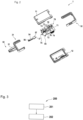
- the locking device element 1 comprises a key blade 2 formed by a housing 10.
- the housing 10 is composed of a first housing part 11 and a second housing part 12.
- the two housing parts 11, 12 are connected to one another by a frame 30.
- the frame 30 is composed of a first frame part 31 and a second frame part 32.
- a key shank 50 of the locking device element 1 extends from the first frame part 31.
- the key shank 50 comprises a key shank base body 51, which is in particular formed monolithically with the first frame part 31.
- An insert element 54 is inserted into the key shaft base body 51. At least one electrical conductor extends through this insert element 54 as part of a transmission device for transmitting energy and/or electronic data to the locking cylinder 101.
- the electrical conductor points The tip of the key shaft 50 has at least one lock cylinder contact surface 56 as part of the transmission device.
- the insert element 54 has at least one circuit board contact surface 57, which is located inside the housing 10.
- FIG. 2 illustrates an electronics 70 of the locking device element 1.
- This electronics 70 comprises a printed circuit board 71.
- a processing device 72 which is designed as a microcontroller.
- the electronics 70 comprises a first time element 76 and a second time element 77.
- the first time element 76 is located on the circuit board 71, but outside the processing device 72, and is preferably designed as a real-time clock.
- the second time element 77 is located inside the processing device 72, i.e. in particular inside the microcontroller.
- the first time element 76 outputs a first time signal indicating the first time t1.
- the second time element 77 is designed to generate a second time signal within the processing device 72 indicating the second time t2.
- a first time t1 is thus measured by the first time element 76.
- a second time t2 is thus measured by the second time element 77.
- the first timing element 76 is electrically connected to the processing device 72 for transmitting the first timing signal.
- the first timing element 76 is designed, in particular, as a real-time clock (RTC) with an oscillating crystal.
- the electronics 70 on the circuit board 71 comprises a button 73.
- the button 73 can be actuated by pressing the first housing part 11
- the locking device element 1 can, for example, establish a connection with the device 103 using the button 73.
- the electronics 70 comprises a socket 74, for example formed from a USB port, for charging an energy storage device 85 of the locking device element 1.
- Fig. 2 further shows that the electronics 70 includes a lighting device 75.
- This lighting device 75 can, for example, be used to output a warning message or to indicate another state of the locking device element 1.
- Fig. 2 further shows that the electronics 70 comprises a wireless communication module 78, with which in particular the data transmission with the device 103 is possible.
- an electrical actuator in particular an electric motor, must be energized in the locking cylinder 101.
- This enables a locking element (not shown) in the locking cylinder 101 to release a lock between a rotor 105 of the locking cylinder 101 and a stator 106 of the locking cylinder 101, so that the rotor 105 can rotate in the stator 106.
- This enables a rotation of a driver 107 of the locking cylinder 101.
- a corresponding actuator and a corresponding locking element are described, for example, in the EP 4191004 A1 disclosed.
- the rotor 105 can always be rotatable within the stator 106.
- the rotor is connected to the driver 107 in a rotationally fixed manner by an actuator, thereby enabling rotation of the driver 107.
- the processing device 72 compares an access authorization time window stored electronically in the processing device 72 with the first and/or second time. If the used time is in the access authorization time window, the access decision step is concluded with a positive result, otherwise with a negative result. The processing device 72 also checks whether the first and/or the second time is after an access authorization validity start date stored electronically in the processing device 72. If this is the case, this access decision step is concluded with a positive result, otherwise with a negative result. The processing device 72 also checks whether the first and/or the second time is before an access authorization validity end date stored electronically in the processing device 72. If this is the case, this access decision step is concluded with a positive result, otherwise with a negative result.
- At least one locking cylinder ID can be electronically stored on the locking device element 1.
- the locking device element 1 is configured to receive the locking cylinder ID to be stored in previously encrypted form from the backend system 104.
- the locking device element 1 can decrypt the locking cylinder ID using encryption information specific to the locking device element 1.
- the locking device element 1 is configured to check, as an access condition, whether a locking cylinder ID received from a locking cylinder 101 matches the stored locking cylinder ID; this also corresponds to an access decision step. If a stored locking cylinder ID matches the received locking cylinder ID, the access decision step is concluded with a positive result; otherwise, with a negative result.
- At least one further access decision step can be carried out by the locking cylinder 101.
- the transmitted result is checked to see whether it was sent by an authorized
- the locking device element 1 is accessed, for example, by appropriate decryption.
- a key ID can be transmitted to the locking cylinder 101, wherein the locking cylinder checks, as an access decision step, whether the key ID is listed in a whitelist or blacklist stored in the locking cylinder 101. If all access decision steps have been completed with a positive result, the actuator is energized and access is granted by the user rotating the driver 107.
- the stored data for comparison in the access decision steps e.g., access authorization time window, access authorization validity start, access authorization validity end, locking cylinder ID
- the device 103 cannot decrypt the data.
- the data can be linked to one another; for example, different locking cylinder IDs can be assigned different access authorization time windows.
- the locking device element 1 is designed to receive an update time signal indicating an update time upt from the backend system 104 (see Figure 5 ), in particular via wireless short-range communication with the device 103.
- an update time upt is sent from the backend system 104 via the device 103 to the locking device element 1.
- the update time upt is encrypted in such a way that the device 103 cannot decrypt the update time upt.
- the update time upt is preferably decrypted using encryption information specific to the locking device element 1.
- the locking device element 1 can be triggered via the device 103 at the backend system 104 Sends a request, e.g., to receive the update time upt and/or to update the data for comparison in the access decision steps.
- the time can be measured continuously. This eliminates the need to measure the time in the locking cylinder 101 and to provide a corresponding energy storage device in the locking cylinder.
- Fig. 3 shows purely schematically the steps of the access method 200 defined in the general part of the description with the checking step 201 and the further step 202 depending on the outcome of the checking step 201.
- the processing device 72 is designed to carry out the checking step 201 based on the first time, and wherein the locking device element 1 is designed to carry out at least one further step 202 depending on the outcome of the checking step 201.
- the described time-dependent access decision steps can be considered an example of a verification step 201.
- a further step can be considered the transmission of the information to the locking cylinder 101.
- FIGS. 4 to 6 show further examples of checking steps 201 and further steps 202, which can each be carried out in the locking device element 1.
- the processing device 72 is designed to compare the first time t1 with the second time t2 as a checking step 201, in particular to compare the first time signal with the second time signal, e.g. by comparing the difference I t1 - t2 I with a stored time difference dt1.
- step 202 Based on the output of the checking step 201, preferably if the first time and the second time differ by more than a stored first time difference dt1 or corresponds to the stored first time difference dt1, Further step 202 initiates an at least temporary denial of access to the physical area by the processing device 72.
- the status of the locking device element 1 is set to "manipulated.”
- verification step 201 may include receiving an error message from the first timing element 76 by the processing device 72, for example, because the crystal is no longer oscillating. In this case, too, the status of the locking device element 1 is set to "tampered.”
- the locking device element 1 sends an unlocking request E to the backend system 104 via the device 103. This corresponds to a subsequent step 203.
- the locking device element 1 can then receive an approval message G from the backend system 104 in a step 204.
- the update time upt is received from the locking device element 1 in addition to the approval message. Using this update time upt, the first time t1 can be set at the first time element 76 and/or the second time t2 can be set at the second time element 77.
- the update time upt is sent in encrypted form from the backend system 104 to the locking device element 1 in such a way that the device 103 cannot manipulate the update time upt.
- the update time upt is only adopted if there is a continuous connection between the backend system 104 and the locking device element 1, so that the update time upt is not buffered in the device 103 for a long time and becomes inaccurate.
- the time between the date of the unlock request E and receipt of the response G + upt can be used as a measure of the connection to the backend system 104.
- the device 103 receives a buffer time period zt, with which the update time upt was buffered between the backend system on the device 103, the Approval message added.
- the first and/or second time t1, t2 is adjusted by the update time upt, which is corrected by the buffering time zt. To prevent manipulation, it can be provided that the adjustment only occurs if the buffering time zt does not exceed a time period stored in the processing device 72.
- the check 201 in which the first and second times t1, t2 are compared, is carried out at regular intervals and as an access decision step within an access procedure.
- the locking device element 1 can be configured to initiate, preferably carry out itself, a granting of access to the physical area taking into account at least one further access condition based on the output of the checking step 201, preferably if the first time t1 and the second time t2 differ by less than the stored first time difference dt1, as a further step 202; in particular, the locking device element 1 is configured to compare a time, in particular the first and/or the second time, with an access authorization time window and/or with an access authorization validity start and/or with an access authorization validity end, in order to check the access condition. This applies if the first and second times t1, t2 are compared within an access method.
- the locking device element 1 can be designed to correct the second time t2 based on the first time t1 as a further step 202, in particular to set the second time element 77 after the first time t1, based on the output of the checking step 201, preferably if the first time t1 and the second time t2 differ by less than the stored first time difference dt1.
- the locking device element 1 is designed to receive a buffer time period zt, with which the update time upt between the backend system 104 and the locking device element 1 was buffered on the device 103.
- the buffer time period zt is corrected update time upt is compared with the first time t1 and/or second time t2 (not shown), and as a further step 202, if the update time upt corrected by the buffer time period zt differs from the first time t1 and/or second time t1 by less (i.e., a lower value) than a stored limit value g, to set the first time element 76 and/or the second time element 77 based on the update time upt corrected by the buffer time period zt ("sync"), or, if the update time upt corrected by the buffer time period zt differs from the first and/or second time t1, t2 by more (i.e., a higher value) than a stored limit
- the time period ZS indicates how long ago the first and/or second time t1, t2 was set by an update time upt. If the limit value g is exceeded and the update time upt is discarded, the time period ZS is not restarted ("no reset ZS").
- the time at which the first and/or second time t1, t2 was set after the update time upt can be stored in the processing device 72.
- Verification steps are shown to ensure that the first and/or second time t1, t2 are regularly set by the update time upt.
- the verification step 201 in Figure 6 involves determining a time period ZS since the last adjustment using the first time t1 and/or the second time t2 and comparing it with at least one stored update limit value ZD1, ZD2.
- a warning ("Warn.") is issued in a further step 202 to carry out the adjustment by means of an update time upt.
- the status of the locking device element 1 is set to "inaccurate” in a further step 202.
- the "inaccurate” status it is not possible to use the locking device element 1 for an access procedure with a positive Output. This means that no locking cylinder 101 can achieve rotation of the driver 107 by means of the locking device element 1 in the "inaccurate” state.
- the "inaccurate” status can be canceled by performing a time synchronization with the backend system 104. This is shown in the lower line of Figure 6 shown.
- a request for an update time upt is sent to the backend system 104, whereupon the update time upt is received by the backend system 104.
- the buffering time period zt is missing because it is ensured that the connection between the backend system 104, the device 103 and the locking device element 1 is established.
- the time synchronization with the backend system 104 can be performed using the buffer time period zt, as described above in connection with Figure 5 described.
- a step 208 the time synchronization is performed, which removes the status "inaccurate".
- the locking cylinder 101 for example, particularly if the locking cylinder 101 can be actuated by means of a knob, can correspond to the locking device element 1 and communicate directly with the device 103 via short-range communication. The communication between the device 103 and the backend system 104 is maintained. In this case, the corresponding access decision steps are carried out in the locking cylinder 101.
- an electromechanical fitting, a padlock, or a smart lock can function as the locking device element 1 and accordingly communicate directly with the device 103 and carry out the corresponding access decision steps.
Landscapes
- Physics & Mathematics (AREA)
- General Physics & Mathematics (AREA)
- Engineering & Computer Science (AREA)
- Manufacturing & Machinery (AREA)
- Lock And Its Accessories (AREA)
Priority Applications (4)
| Application Number | Priority Date | Filing Date | Title |
|---|---|---|---|
| EP23199842.8A EP4531009A1 (fr) | 2023-09-26 | 2023-09-26 | Élément de dispositif de verrouillage destiné à être utilisé dans un procédé d'accès |
| CN202480058486.6A CN121889840A (zh) | 2023-09-26 | 2024-08-28 | 用于在访问方法中使用的锁定装置元件 |
| PCT/EP2024/074061 WO2025067803A1 (fr) | 2023-09-26 | 2024-08-28 | Élément de dispositif de verrouillage destiné à être utilisé dans un processus d'accès |
| AU2024353210A AU2024353210A1 (en) | 2023-09-26 | 2024-08-28 | Locking device element for use in an access process |
Applications Claiming Priority (1)
| Application Number | Priority Date | Filing Date | Title |
|---|---|---|---|
| EP23199842.8A EP4531009A1 (fr) | 2023-09-26 | 2023-09-26 | Élément de dispositif de verrouillage destiné à être utilisé dans un procédé d'accès |
Publications (1)
| Publication Number | Publication Date |
|---|---|
| EP4531009A1 true EP4531009A1 (fr) | 2025-04-02 |
Family
ID=88204105
Family Applications (1)
| Application Number | Title | Priority Date | Filing Date |
|---|---|---|---|
| EP23199842.8A Pending EP4531009A1 (fr) | 2023-09-26 | 2023-09-26 | Élément de dispositif de verrouillage destiné à être utilisé dans un procédé d'accès |
Country Status (4)
| Country | Link |
|---|---|
| EP (1) | EP4531009A1 (fr) |
| CN (1) | CN121889840A (fr) |
| AU (1) | AU2024353210A1 (fr) |
| WO (1) | WO2025067803A1 (fr) |
Citations (7)
| Publication number | Priority date | Publication date | Assignee | Title |
|---|---|---|---|---|
| US20110050390A1 (en) * | 1994-11-15 | 2011-03-03 | Denison William D | Electronic Access Control Device and Management System |
| US20140375422A1 (en) * | 2013-06-20 | 2014-12-25 | Parakeet, Llc | Technologies and methods for security access |
| US20160269168A1 (en) * | 2013-12-05 | 2016-09-15 | Deutsche Post Ag | Time synchronization |
| EP1899924B1 (fr) | 2005-06-10 | 2017-08-30 | Assa Ab | Cle de verrouillage et son procede de fabrication |
| US20190025873A1 (en) * | 2017-07-21 | 2019-01-24 | Schlage Lock Company Llc | Secure real-time clock update in an access control system |
| EP4099283A1 (fr) * | 2021-06-01 | 2022-12-07 | ASSA ABLOY Sicherheitstechnik GmbH | Clé pourvue de générateur et d'horloge en temps réel |
| EP4191004A1 (fr) | 2021-12-03 | 2023-06-07 | dormakaba Schweiz AG | Dispositif d'arrêt pour un élément de fermeture |
-
2023
- 2023-09-26 EP EP23199842.8A patent/EP4531009A1/fr active Pending
-
2024
- 2024-08-28 CN CN202480058486.6A patent/CN121889840A/zh active Pending
- 2024-08-28 WO PCT/EP2024/074061 patent/WO2025067803A1/fr active Pending
- 2024-08-28 AU AU2024353210A patent/AU2024353210A1/en active Pending
Patent Citations (7)
| Publication number | Priority date | Publication date | Assignee | Title |
|---|---|---|---|---|
| US20110050390A1 (en) * | 1994-11-15 | 2011-03-03 | Denison William D | Electronic Access Control Device and Management System |
| EP1899924B1 (fr) | 2005-06-10 | 2017-08-30 | Assa Ab | Cle de verrouillage et son procede de fabrication |
| US20140375422A1 (en) * | 2013-06-20 | 2014-12-25 | Parakeet, Llc | Technologies and methods for security access |
| US20160269168A1 (en) * | 2013-12-05 | 2016-09-15 | Deutsche Post Ag | Time synchronization |
| US20190025873A1 (en) * | 2017-07-21 | 2019-01-24 | Schlage Lock Company Llc | Secure real-time clock update in an access control system |
| EP4099283A1 (fr) * | 2021-06-01 | 2022-12-07 | ASSA ABLOY Sicherheitstechnik GmbH | Clé pourvue de générateur et d'horloge en temps réel |
| EP4191004A1 (fr) | 2021-12-03 | 2023-06-07 | dormakaba Schweiz AG | Dispositif d'arrêt pour un élément de fermeture |
Also Published As
| Publication number | Publication date |
|---|---|
| CN121889840A (zh) | 2026-04-17 |
| AU2024353210A1 (en) | 2026-03-12 |
| WO2025067803A1 (fr) | 2025-04-03 |
Similar Documents
| Publication | Publication Date | Title |
|---|---|---|
| EP3053149B2 (fr) | Synchronisation dans le temps | |
| DE60014362T2 (de) | Schlüssel und schlossvorrichtung | |
| EP3327679B1 (fr) | Procédé de contrôle d'accès d'un groupe de personnes au moyen de plusieurs appareils de lecture et de plusieurs jetons | |
| EP3416140B1 (fr) | Procédé et dispositif d'authentification d'un utilisateur sur un véhicule | |
| EP3103057B1 (fr) | Procédé d'accès à une baie physiquement sécurisée ainsi qu'infrastructure informatique | |
| DE102016201603A1 (de) | Verfahren und Vorrichtungen zum Entriegeln eines Kraftfahrzeugs mit einem Motorstart- und/oder Fahrzeugzugangssystem | |
| DE102012219112A1 (de) | Verwenden einer PUF zur Prüfung einer Authentisierung, insbesondere zum Schutz vor unberechtigtem Zugriff auf eine Funktion eines ICs oder Steuergerätes | |
| DE102013215303A1 (de) | Mobiles elektronisches Gerät | |
| EP3135546B1 (fr) | Clé d'automobile, système de communication et procédé associé | |
| EP3422628B1 (fr) | Procédé, dispositif de sécurité et système de sécurité | |
| EP3848911A1 (fr) | Procédé et dispositif d'authentification d'un utilisateur d'une boîte aux lettres | |
| WO2025067803A1 (fr) | Élément de dispositif de verrouillage destiné à être utilisé dans un processus d'accès | |
| DE102018132979A1 (de) | Abgesichertes und intelligentes Betreiben einer Ladeinfrastruktur | |
| WO2016041843A1 (fr) | Procédé et agencement permettant d'autoriser une action au niveau d'un système en libre-service | |
| DE102015108026A1 (de) | Schließanlage und Verfahren zum Betrieb einer Schließanlage für eine Gebäudetür | |
| DE102013100756B3 (de) | Verfahren und Vorrichtung zur Authentifizierung eines Nutzers | |
| DE102010019467A1 (de) | Kontaktlos arbeitendes Zugangssystem | |
| DE4141766A1 (de) | Verfahren zur sicherung einer elektronischen datenuebertragung | |
| DE102020123756B3 (de) | Verfahren zur Nutzungsfreigabe sowie Funktionsfreigabeeinrichtung hierzu | |
| EP3051504B1 (fr) | Systeme d'acces electronique comprenant plusieurs minuteries et memoires | |
| DE102021204529A1 (de) | Vorrichtung und Verfahren zur drahtlosen Kommunikation | |
| EP3288215A1 (fr) | Procede et dispositif de sortie de certificats d'authentification et module de securite | |
| EP4087184B1 (fr) | Procédé d'authentification des interactions indépendamment d'une heure système , ainsi que dispositif de mise en uvre dudit procédé et détecteur de flamme doté d'un tel dispositif | |
| DE102013010171A1 (de) | Rechnernetz, Netzknoten und Verfahren zur Bereitstellung von Zertifizierungsinformationen | |
| WO2020074313A1 (fr) | Clé de véhicule destinée au déverrouillage et/ou au verrouillage au moins partiels d'un véhicule, procédé de déverrouillage et/ou de verrouillage au moins partiels d'un véhicule à l'aide d'une clé de véhicule |
Legal Events
| Date | Code | Title | Description |
|---|---|---|---|
| PUAI | Public reference made under article 153(3) epc to a published international application that has entered the european phase |
Free format text: ORIGINAL CODE: 0009012 |
|
| STAA | Information on the status of an ep patent application or granted ep patent |
Free format text: STATUS: THE APPLICATION HAS BEEN PUBLISHED |
|
| AK | Designated contracting states |
Kind code of ref document: A1 Designated state(s): AL AT BE BG CH CY CZ DE DK EE ES FI FR GB GR HR HU IE IS IT LI LT LU LV MC ME MK MT NL NO PL PT RO RS SE SI SK SM TR |
|
| STAA | Information on the status of an ep patent application or granted ep patent |
Free format text: STATUS: REQUEST FOR EXAMINATION WAS MADE |
|
| 17P | Request for examination filed |
Effective date: 20251002 |