EP4531177A1 - Gehäuse für eine elektrische batterie und montageverfahren dafür - Google Patents
Gehäuse für eine elektrische batterie und montageverfahren dafür Download PDFInfo
- Publication number
- EP4531177A1 EP4531177A1 EP23306610.9A EP23306610A EP4531177A1 EP 4531177 A1 EP4531177 A1 EP 4531177A1 EP 23306610 A EP23306610 A EP 23306610A EP 4531177 A1 EP4531177 A1 EP 4531177A1
- Authority
- EP
- European Patent Office
- Prior art keywords
- components
- electric battery
- housing
- cover
- locking
- Prior art date
- Legal status (The legal status is an assumption and is not a legal conclusion. Google has not performed a legal analysis and makes no representation as to the accuracy of the status listed.)
- Pending
Links
Images


Classifications
-
- H—ELECTRICITY
- H01—ELECTRIC ELEMENTS
- H01M—PROCESSES OR MEANS, e.g. BATTERIES, FOR THE DIRECT CONVERSION OF CHEMICAL ENERGY INTO ELECTRICAL ENERGY
- H01M50/00—Constructional details or processes of manufacture of the non-active parts of electrochemical cells other than fuel cells, e.g. hybrid cells
- H01M50/20—Mountings; Secondary casings or frames; Racks, modules or packs; Suspension devices; Shock absorbers; Transport or carrying devices; Holders
- H01M50/204—Racks, modules or packs for multiple batteries or multiple cells
- H01M50/207—Racks, modules or packs for multiple batteries or multiple cells characterised by their shape
- H01M50/209—Racks, modules or packs for multiple batteries or multiple cells characterised by their shape adapted for prismatic or rectangular cells
-
- H—ELECTRICITY
- H01—ELECTRIC ELEMENTS
- H01M—PROCESSES OR MEANS, e.g. BATTERIES, FOR THE DIRECT CONVERSION OF CHEMICAL ENERGY INTO ELECTRICAL ENERGY
- H01M50/00—Constructional details or processes of manufacture of the non-active parts of electrochemical cells other than fuel cells, e.g. hybrid cells
- H01M50/20—Mountings; Secondary casings or frames; Racks, modules or packs; Suspension devices; Shock absorbers; Transport or carrying devices; Holders
- H01M50/262—Mountings; Secondary casings or frames; Racks, modules or packs; Suspension devices; Shock absorbers; Transport or carrying devices; Holders with fastening means, e.g. locks
-
- H—ELECTRICITY
- H01—ELECTRIC ELEMENTS
- H01M—PROCESSES OR MEANS, e.g. BATTERIES, FOR THE DIRECT CONVERSION OF CHEMICAL ENERGY INTO ELECTRICAL ENERGY
- H01M50/00—Constructional details or processes of manufacture of the non-active parts of electrochemical cells other than fuel cells, e.g. hybrid cells
- H01M50/20—Mountings; Secondary casings or frames; Racks, modules or packs; Suspension devices; Shock absorbers; Transport or carrying devices; Holders
- H01M50/271—Lids or covers for the racks or secondary casings
-
- H—ELECTRICITY
- H01—ELECTRIC ELEMENTS
- H01M—PROCESSES OR MEANS, e.g. BATTERIES, FOR THE DIRECT CONVERSION OF CHEMICAL ENERGY INTO ELECTRICAL ENERGY
- H01M2220/00—Batteries for particular applications
- H01M2220/20—Batteries in motive systems, e.g. vehicle, ship, plane
-
- Y—GENERAL TAGGING OF NEW TECHNOLOGICAL DEVELOPMENTS; GENERAL TAGGING OF CROSS-SECTIONAL TECHNOLOGIES SPANNING OVER SEVERAL SECTIONS OF THE IPC; TECHNICAL SUBJECTS COVERED BY FORMER USPC CROSS-REFERENCE ART COLLECTIONS [XRACs] AND DIGESTS
- Y02—TECHNOLOGIES OR APPLICATIONS FOR MITIGATION OR ADAPTATION AGAINST CLIMATE CHANGE
- Y02E—REDUCTION OF GREENHOUSE GAS [GHG] EMISSIONS, RELATED TO ENERGY GENERATION, TRANSMISSION OR DISTRIBUTION
- Y02E60/00—Enabling technologies; Technologies with a potential or indirect contribution to GHG emissions mitigation
- Y02E60/10—Energy storage using batteries
Definitions
- Motor vehicles with electric or hybrid traction or propulsion have one or more “battery packs” connected to a power network to supply one or more electric motors (traction or propulsion).
- battery pack refers to a mechanical assembly of several battery modules.
- a battery module refers to a set of electrochemical cells, for example prismatic cells, electrically connected to each other.
- the battery pack generally comprises, in addition to modules, a body housing the module(s) and a cover covering the body, the cover and the body forming a rigid housing to keep the cells of the module(s) compressed together and to protect them from external elements.
- the cover is generally screwed or glued to the body.
- a battery pack which is composed of an upper cover, a shell arranged at the bottom of the upper cover, a battery unit arranged in the shell, a plurality of second connecting plates arranged at both ends of the top of the shell, and a plurality of first connecting plates arranged at both ends of the bottom of the upper cover.
- a connecting block is arranged at the bottom of each first connecting plate, an insertion column is arranged at the bottom of each connecting block, a connecting groove is formed in each second connecting plate and fitted to the corresponding connecting block in an insertion mode, a second transverse screw hole is formed in each second connecting plate, and a third transverse screw hole is formed in the side wall of each connecting groove. connection.
- Each connecting block is provided with a first transverse screw hole, and after inserting the upper cover to the connecting groove in the second connecting plate through the connecting block and the insertion column at the bottom of the first connecting plate, the upper cover is fixed with the screw holes using locking bolts, so that the effect of connecting and fixing the upper cover body is achieved.
- the invention aims to overcome the drawbacks of the state of the art and to propose a battery box whose assembly and disassembly are simplified.
- a housing for an electric battery comprising: two components, consisting of a support for a set of prismatic cells, and a cover intended to cover the set of prismatic cells; and a locking system movable between a locking position and an unlocking position and ensuring in the locking position the joining of the two components.
- the locking system of the housing comprises a lever fixed on a first of the two components and guided in rotation relative to the first of the two components between the locking position and the unlocking position and which, in the locking position, is elastically deformed to wedge into attachment means secured to the first of the two components, and to bear against a surface of the second of the two components, ensuring the joining of the two components.
- a locking system including a lever to secure the two components eliminates the need for glue and/or screws and simplify the assembly and disassembly of the battery box. The assembly time of the two components is also reduced.
- the prismatic cell array is a compact assembly of prismatic cells electrically connected together in series or parallel, the assembly forming a rectangular parallelepiped.
- the cover has at least one bottom wall located opposite and at a distance from the support and two side walls projecting from the bottom wall and coming into contact with the support.
- the support may comprise a flat plate with dimensions greater than the rectangular base of the set of prismatic cells.
- the cover is sized to cover the upper face of the cell assembly and at least partially two opposite side faces of the cell assembly.
- the lever attachment means are attached to the first of the two components. According to another embodiment, the attachment means are directly formed on the first of the two components.
- the attachment means comprise at least one housing formed in the first of the two components.
- the housing accommodates and holds the arms of the lever in position when it is locked.
- the attachment means contain four semi-cylindrical fasteners into which the lever is inserted.
- the lever presses against the surface of the second of the two components by applying a predetermined locking force.
- the predetermined locking force is preferably between 100 N and 1000 N.
- the locking force is applied mechanically on an assembly station.
- the locking force is applied manually.
- the two components are at least partly made of insulating material(s). At least the material of the component intended to cover the set of prismatic cells is an electrical insulator. In addition, the materials of the two components are capable of withstanding high pressures (9 bars, or 9.10 5 Pa). Finally, the materials of the two components remain elastically deformable when the housing is subjected to maximum stresses.
- the housing comprises a fixing assembly comprising one or more protruding elements formed on one of the two components, abutting against one or more stop elements formed on the other of the two components, the fixing assembly holding the two components in a locking position by form-fitting.
- the fixing assembly allows rotation of the component intended to cover the cell assembly relative to the component serving as a support for the cell assembly, in order to move the battery case from an open configuration to a closed configuration before locking it.
- the protruding element(s) include one or more fixing lugs and the stopping element(s) include one or more holes complementary to the fixing lugs.
- the assembly process is fully automated, which makes it possible to increase the production speed of the housings.
- the process is partially or entirely carried out manually.
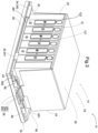
- a battery case 10 is illustrated housing a set of prismatic cells 12 and formed of a first component 14 and a second component 16.
- the set of prismatic cells 12 is a compact assembly in series or in parallel of prismatic cells 121 forming a rectangular parallelepiped. At the two longitudinal ends of the set of cells there are protective walls 122 making it possible to mechanically maintain the set of prismatic cells 12.
- the first component 14 of the battery housing 10 is a cover 18, preferably metallic, obtained for example by folding a plate or molding, and intended to at least partially cover the set of cells 12.
- the cover 18 is U-shaped, open towards the second component 16 of the housing 10. It comprises a bottom wall 20, connecting a first side wall 22 and a second side wall 24.
- the length of the bottom wall 20 is preferably greater than the length of the first side wall 22 and the length of the second side wall 24, and the width of the bottom wall 20 is preferably equal to the width of the first side wall 22 and the width of the second side wall 24.
- the bottom wall 20, the first side wall 22 and the second side wall 24 are made of metallic material(s), for example aluminum and covered at least partially with insulating material(s).
- the bottom wall 20 of the cover 18 serves to cover the upper face of the set of cells 12, the first and second side walls ( 22, 24 ) of the cover 18 being intended to partially cover the two outer faces of the protective walls 122 of the set of cells 12.
- a stepped bearing surface 28 composed of a first surface 281, a second surface 282 and a connecting surface 283.
- the first and second surfaces ( 281, 282 ) are parallel to each other and perpendicular to the second side wall 24, the intermediate surface 283 being oblique and making it possible to connect the first surface 281 to the second surface 282.
- the stepped bearing surface 28 is plastically deformable.
- the second component 16 of the battery housing 10 constitutes a support for the set of prismatic cells 12 and comprises a flat plate 30 and a frame 32 on which are formed/fixed hooking means 34 and a stop element 36.
- the flat plate 30 is a rectangular plate, of length and width greater than the length and width of the set of prismatic cells 12.
- the flat plate 30 is coated with an electrical insulator.
- At the four ends of the flat plate are drilled tapped holes 381.
- the frame 32 of the second component 16 is obtained by stamping. It comprises an outer casing 40 and a hole 42 drilled in its center.
- the hole 42 is through and rectangular, of length and width equal to the length and width of the set of prismatic cells 12.
- the outer casing 40 is formed of two lengths equal to the lengths of the flat plate 30 and each comprising a flank of material 341 oriented towards the outside of the hole 42, of a width equal to the width of the flat plate 30 and of a width comprising a rectangular material recess 44 oriented towards the rectangular through hole 42.
- the material of the frame 32 is deformed so as to obtain two open guide bearings 46, the opening being oriented towards the rectangular through hole 42.
- At the four ends of the frame are drilled through holes 382 aligned with the tapped holes 381 of the flat plate 40 and allowing the frame 32 to be screwed to the plate 40.
- the attachment means 34 are formed on the two lengths of the outer casing 40 of the frame 32, the attachment means 34 comprising two hooks 341 formed by the deformation of the two sides of material, and two notches 342 machined separately and attached to the frame 32.
- the stop element 36 On the width of the frame 32 facing the width comprising the material removal 44 is attached the stop element 36.
- the stop element 36 is a rectangular strip 361 having a light 362 (insertion hole) in its center.
- the battery housing 10 comprises a lever 48 comprising two perpendicular arms 481 connected by a middle section 482.
- the middle section 482 of the lever 48 is inserted into the guide bearings 46 of the frame 32 of the second component 16, so as to make the lever 48 rotatable around the middle section 482, and to move the battery housing 10 from an unlocked position to a locked position.
- the middle section 482 of the lever is deformed in its center to form a protrusion, so that in the unlocked position, the protrusion is at a distance from the stepped bearing surface 28, and in the locked position, the protruding wall exerts pressure on the bearing surface 28, in particular on the intermediate surface 283 of the bearing surface 28 to ensure the hermetic locking of the housing 10.
- FIG. 2 represents the battery housing 10 in an unlocked position.
- the first and second components ( 14, 16 ) are held in contact using a fastening element 50, the fastening element being formed by the engagement of the fastening lugs ( 261, 262 ) of the first component 14 in a lumen 362 of the second component 16.
- the fastening element 50 allows rotation of the first component 14 relative to the second component 16.
- the battery housing 10 is shown in a locked configuration.
- the two components ( 14, 16 ) are fixed on one side by the fixing element 50, and on the other by the locking of the lever 48.
- the arms of the lever 481 engaged in the hooking means 34 of the second component 16 and the middle section 482 of the lever elastically deform the bearing surface 28 of the second component 16.
- the pressure applied by the lever 48 on the bearing surface 28 induces a concave curvature of the bottom wall 20 of the cover 18 of the first component 14.
- the maximum displacement of the bottom wall 20 of the cover 18 is located at its center and remains below the elastic limit.
- the fixing element 50 of the housing 10 comprises a projecting element 26 secured to the second component 16 and engaging in a stop element 36 fixed to the first component 14.
- the fixing element 50 is formed by a projecting element 26 of the first component 14 engaging in a projecting element 26 of the second component 16, for example a first hook fixed to the first component 14 engaging in a second hook perpendicular to the first hook and fixed to the second component 16.
- all the attachment means 34 are formed directly on the frame 32 of the second component 16, the attachment means 34 being obtained by the deformation of material flanks 341 of the frame 32.
- the attachment means 34 and the stop element 36 are attached directly to the plate 30 of the second component 16, the second component 16 not comprising a frame 32.
- the projecting elements 26 and the bearing surface 28 are formed on the second component 16, and the hooking means 34, the stop element 36 and the guide bearings 46 are fixed on the first component 14.
- the lever 48 is inserted on the first component 14 and comes into contact with the bearing surface 28 of the second component 16.
Landscapes
- Chemical & Material Sciences (AREA)
- Chemical Kinetics & Catalysis (AREA)
- Electrochemistry (AREA)
- General Chemical & Material Sciences (AREA)
- Battery Mounting, Suspending (AREA)
Priority Applications (2)
| Application Number | Priority Date | Filing Date | Title |
|---|---|---|---|
| EP23306610.9A EP4531177A1 (de) | 2023-09-27 | 2023-09-27 | Gehäuse für eine elektrische batterie und montageverfahren dafür |
| US18/899,253 US20250105423A1 (en) | 2023-09-27 | 2024-09-27 | Electric battery housing and associated assembly method |
Applications Claiming Priority (1)
| Application Number | Priority Date | Filing Date | Title |
|---|---|---|---|
| EP23306610.9A EP4531177A1 (de) | 2023-09-27 | 2023-09-27 | Gehäuse für eine elektrische batterie und montageverfahren dafür |
Publications (1)
| Publication Number | Publication Date |
|---|---|
| EP4531177A1 true EP4531177A1 (de) | 2025-04-02 |
Family
ID=88315603
Family Applications (1)
| Application Number | Title | Priority Date | Filing Date |
|---|---|---|---|
| EP23306610.9A Pending EP4531177A1 (de) | 2023-09-27 | 2023-09-27 | Gehäuse für eine elektrische batterie und montageverfahren dafür |
Country Status (2)
| Country | Link |
|---|---|
| US (1) | US20250105423A1 (de) |
| EP (1) | EP4531177A1 (de) |
Citations (6)
| Publication number | Priority date | Publication date | Assignee | Title |
|---|---|---|---|---|
| US20080268330A1 (en) * | 2005-03-30 | 2008-10-30 | Johnson Controls Technology Company | Battery system |
| CN208608263U (zh) * | 2018-07-18 | 2019-03-15 | 安徽鲁子产业技术研发有限公司 | 一种新能源汽车电池组的保护装置 |
| CN212934743U (zh) | 2020-07-13 | 2021-04-09 | 惠州市亿兆能源科技有限公司 | 一种电池模组上盖组件 |
| JP7045581B2 (ja) * | 2018-03-12 | 2022-04-01 | エルジー エナジー ソリューション リミテッド | 電気自動車の補助バッテリー収納装置 |
| CN114614175A (zh) * | 2022-03-21 | 2022-06-10 | 江苏金博途科技有限公司 | 一种矿井用的不间断持续放电锂电池 |
| US11527791B2 (en) * | 2018-10-04 | 2022-12-13 | Robert Bosch Gmbh | Battery module |
-
2023
- 2023-09-27 EP EP23306610.9A patent/EP4531177A1/de active Pending
-
2024
- 2024-09-27 US US18/899,253 patent/US20250105423A1/en active Pending
Patent Citations (6)
| Publication number | Priority date | Publication date | Assignee | Title |
|---|---|---|---|---|
| US20080268330A1 (en) * | 2005-03-30 | 2008-10-30 | Johnson Controls Technology Company | Battery system |
| JP7045581B2 (ja) * | 2018-03-12 | 2022-04-01 | エルジー エナジー ソリューション リミテッド | 電気自動車の補助バッテリー収納装置 |
| CN208608263U (zh) * | 2018-07-18 | 2019-03-15 | 安徽鲁子产业技术研发有限公司 | 一种新能源汽车电池组的保护装置 |
| US11527791B2 (en) * | 2018-10-04 | 2022-12-13 | Robert Bosch Gmbh | Battery module |
| CN212934743U (zh) | 2020-07-13 | 2021-04-09 | 惠州市亿兆能源科技有限公司 | 一种电池模组上盖组件 |
| CN114614175A (zh) * | 2022-03-21 | 2022-06-10 | 江苏金博途科技有限公司 | 一种矿井用的不间断持续放电锂电池 |
Also Published As
| Publication number | Publication date |
|---|---|
| US20250105423A1 (en) | 2025-03-27 |
Similar Documents
| Publication | Publication Date | Title |
|---|---|---|
| FR3015774A1 (fr) | Systeme de fixation amovible d'une batterie a un support | |
| EP1815097A1 (de) | Elektrisch mit seiner tür verbundener elektrischer schaltschrank | |
| EP1908136A2 (de) | Elektrisches verbindungsendgerät für eine elektrische stromspeicherzelle | |
| FR2988915A3 (fr) | Structure de module de batterie pour cellules li-ion a enveloppe souple et module de batterie correspondant | |
| FR2988914A3 (fr) | Structure de module de batterie a assemblage simplifie pour cellules li-ion a enveloppe souple et un module correspondant | |
| WO2010094898A1 (fr) | Systeme de fixation d'un pack de batterie et procede de montage/demontage automatisable associe | |
| EP4531177A1 (de) | Gehäuse für eine elektrische batterie und montageverfahren dafür | |
| EP3888154A1 (de) | Batteriegehäuse und modulares batteriesystem | |
| EP4028273B1 (de) | Stromversorgungsanordnung für ein kraftfahrzeug | |
| EP3377350B1 (de) | Vorrichtung zum verriegeln eines wiederaufladbaren elektrischen energiespeichermoduls und elektrisches fahrzeug mit einer derartigen vorrichtung | |
| EP4557526B1 (de) | Leistungsanschlussmodul zum klemmen eines elektrischen kabelabschlusses durch ein blatt, dessen mindestens ein verformbares teil zur bildung eines anschlussblockteils einer verbindungsanordnung bildet | |
| FR3101202A1 (fr) | connecteur électrique | |
| EP3948905A1 (de) | Kapazitiver block mit einem abstandshalter | |
| WO2020174166A1 (fr) | Dispositif de connexion pour stator | |
| EP4427291B1 (de) | Elektrisches modul für eine elektrische batterie | |
| FR3144893A1 (fr) | Dispositif de batterie, notamment pour véhicule | |
| FR3138737A1 (fr) | Dispositif pour le maintien d’un élément de stockage d’énergie sur un socle d’un système de stockage d’énergie. | |
| EP4506234A1 (de) | Kraftfahrzeugstruktur mit einem fersenbrett | |
| WO2024056326A1 (fr) | Ensemble pour batterie d'accumulateurs, véhiculé automobile équipé d'un tel ensemble et procede de fabrication d'un tel ensemble | |
| FR3143858A1 (fr) | Batterie de véhicule avec système de rappel élastique | |
| FR3158583A1 (fr) | Condensateur pour bus continu d’un onduleur | |
| EP3869649A1 (de) | Haltevorrichtung, entsprechende anordnung und entsprechendes befestigungsverfahren | |
| FR3122357A1 (fr) | Boitier de batterie de stockage d’électricité pour véhicule, batterie et procédé associés | |
| EP4615725A1 (de) | Reissverschluss für sammelschienen eines batteriesystems eines elektrofahrzeugs und fahrzeug mit solch einem verschluss | |
| WO2020254178A1 (fr) | Moyen de connexion entre deux parties d'une barre omnibus |
Legal Events
| Date | Code | Title | Description |
|---|---|---|---|
| PUAI | Public reference made under article 153(3) epc to a published international application that has entered the european phase |
Free format text: ORIGINAL CODE: 0009012 |
|
| STAA | Information on the status of an ep patent application or granted ep patent |
Free format text: STATUS: THE APPLICATION HAS BEEN PUBLISHED |
|
| AK | Designated contracting states |
Kind code of ref document: A1 Designated state(s): AL AT BE BG CH CY CZ DE DK EE ES FI FR GB GR HR HU IE IS IT LI LT LU LV MC ME MK MT NL NO PL PT RO RS SE SI SK SM TR |
|
| STAA | Information on the status of an ep patent application or granted ep patent |
Free format text: STATUS: REQUEST FOR EXAMINATION WAS MADE |
|
| 17P | Request for examination filed |
Effective date: 20250930 |