EP4531220A1 - Erdschlussunterbrechungssystem für hlk-geräte - Google Patents
Erdschlussunterbrechungssystem für hlk-geräte Download PDFInfo
- Publication number
- EP4531220A1 EP4531220A1 EP24198002.8A EP24198002A EP4531220A1 EP 4531220 A1 EP4531220 A1 EP 4531220A1 EP 24198002 A EP24198002 A EP 24198002A EP 4531220 A1 EP4531220 A1 EP 4531220A1
- Authority
- EP
- European Patent Office
- Prior art keywords
- leakage current
- load
- ground fault
- grounding conductor
- amount
- Prior art date
- Legal status (The legal status is an assumption and is not a legal conclusion. Google has not performed a legal analysis and makes no representation as to the accuracy of the status listed.)
- Pending
Links
Images







Classifications
-
- H—ELECTRICITY
- H02—GENERATION; CONVERSION OR DISTRIBUTION OF ELECTRIC POWER
- H02H—EMERGENCY PROTECTIVE CIRCUIT ARRANGEMENTS
- H02H3/00—Emergency protective circuit arrangements for automatic disconnection directly responsive to an undesired change from normal electric working condition with or without subsequent reconnection ; integrated protection
- H02H3/16—Emergency protective circuit arrangements for automatic disconnection directly responsive to an undesired change from normal electric working condition with or without subsequent reconnection ; integrated protection responsive to fault current to earth, frame or mass
- H02H3/162—Emergency protective circuit arrangements for automatic disconnection directly responsive to an undesired change from normal electric working condition with or without subsequent reconnection ; integrated protection responsive to fault current to earth, frame or mass for AC systems
-
- H—ELECTRICITY
- H02—GENERATION; CONVERSION OR DISTRIBUTION OF ELECTRIC POWER
- H02H—EMERGENCY PROTECTIVE CIRCUIT ARRANGEMENTS
- H02H3/00—Emergency protective circuit arrangements for automatic disconnection directly responsive to an undesired change from normal electric working condition with or without subsequent reconnection ; integrated protection
- H02H3/16—Emergency protective circuit arrangements for automatic disconnection directly responsive to an undesired change from normal electric working condition with or without subsequent reconnection ; integrated protection responsive to fault current to earth, frame or mass
- H02H3/167—Emergency protective circuit arrangements for automatic disconnection directly responsive to an undesired change from normal electric working condition with or without subsequent reconnection ; integrated protection responsive to fault current to earth, frame or mass combined with other earth-fault protective arrangements
-
- G—PHYSICS
- G01—MEASURING; TESTING
- G01R—MEASURING ELECTRIC VARIABLES; MEASURING MAGNETIC VARIABLES
- G01R31/00—Arrangements for testing electric properties; Arrangements for locating electric faults; Arrangements for electrical testing characterised by what is being tested not provided for elsewhere
- G01R31/327—Testing of circuit interrupters, switches or circuit-breakers
- G01R31/3277—Testing of circuit interrupters, switches or circuit-breakers of low voltage devices, e.g. domestic or industrial devices, such as motor protections, relays, rotation switches
-
- G—PHYSICS
- G01—MEASURING; TESTING
- G01R—MEASURING ELECTRIC VARIABLES; MEASURING MAGNETIC VARIABLES
- G01R31/00—Arrangements for testing electric properties; Arrangements for locating electric faults; Arrangements for electrical testing characterised by what is being tested not provided for elsewhere
- G01R31/50—Testing of electric apparatus, lines, cables or components for short-circuits, continuity, leakage current or incorrect line connections
- G01R31/52—Testing for short-circuits, leakage current or ground faults
-
- H—ELECTRICITY
- H02—GENERATION; CONVERSION OR DISTRIBUTION OF ELECTRIC POWER
- H02H—EMERGENCY PROTECTIVE CIRCUIT ARRANGEMENTS
- H02H3/00—Emergency protective circuit arrangements for automatic disconnection directly responsive to an undesired change from normal electric working condition with or without subsequent reconnection ; integrated protection
- H02H3/26—Emergency protective circuit arrangements for automatic disconnection directly responsive to an undesired change from normal electric working condition with or without subsequent reconnection ; integrated protection responsive to difference between voltages or between currents; responsive to phase angle between voltages or between currents
- H02H3/32—Emergency protective circuit arrangements for automatic disconnection directly responsive to an undesired change from normal electric working condition with or without subsequent reconnection ; integrated protection responsive to difference between voltages or between currents; responsive to phase angle between voltages or between currents involving comparison of the voltage or current values at corresponding points in different conductors of a single system, e.g. of currents in go and return conductors
- H02H3/33—Emergency protective circuit arrangements for automatic disconnection directly responsive to an undesired change from normal electric working condition with or without subsequent reconnection ; integrated protection responsive to difference between voltages or between currents; responsive to phase angle between voltages or between currents involving comparison of the voltage or current values at corresponding points in different conductors of a single system, e.g. of currents in go and return conductors using summation current transformers
-
- H—ELECTRICITY
- H02—GENERATION; CONVERSION OR DISTRIBUTION OF ELECTRIC POWER
- H02H—EMERGENCY PROTECTIVE CIRCUIT ARRANGEMENTS
- H02H5/00—Emergency protective circuit arrangements for automatic disconnection directly responsive to an undesired change from normal non-electric working conditions with or without subsequent reconnection
- H02H5/10—Emergency protective circuit arrangements for automatic disconnection directly responsive to an undesired change from normal non-electric working conditions with or without subsequent reconnection responsive to mechanical injury, e.g. rupture of line, breakage of earth connection
- H02H5/105—Emergency protective circuit arrangements for automatic disconnection directly responsive to an undesired change from normal non-electric working conditions with or without subsequent reconnection responsive to mechanical injury, e.g. rupture of line, breakage of earth connection responsive to deterioration or interruption of earth connection
-
- H—ELECTRICITY
- H02—GENERATION; CONVERSION OR DISTRIBUTION OF ELECTRIC POWER
- H02H—EMERGENCY PROTECTIVE CIRCUIT ARRANGEMENTS
- H02H5/00—Emergency protective circuit arrangements for automatic disconnection directly responsive to an undesired change from normal non-electric working conditions with or without subsequent reconnection
- H02H5/12—Emergency protective circuit arrangements for automatic disconnection directly responsive to an undesired change from normal non-electric working conditions with or without subsequent reconnection responsive to undesired approach to, or touching of, live parts by living beings
Definitions
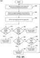
- the process begins at block 802 in which the circuit breaker monitors a first leakage current (or first type thereof) across the line conductor(s) and grounding conductor using a first ground fault sensor (e.g., GFS-1).
- the first ground fault sensor is configured to ignore leakage current across the grounding conductor from the load.
- the circuit breaker monitors a second leakage current (or second type thereof) across the line conductor(s) using a second ground fault sensor (e.g., GFS-2).
- the second ground fault sensor is configured to take into account leakage current across the grounding conductor from the load.
- the circuit breaker monitors the pilot signal across a pilot signal wire using a ground (or pilot) monitor or circuit thereof.
- the circuit breaker determines if the monitored first leakage current satisfies (e.g., greater than or equal to, etc.) a first threshold TH1, which is associated with a let-go current level or other physiological-based current level of the branch circuit or wiring thereof. If so, the circuit breaker detects an occurrence of a ground fault on the branch circuit wiring (e.g., ground fault between the line conductor(s) and Earth ground).
- a first threshold TH1 which is associated with a let-go current level or other physiological-based current level of the branch circuit or wiring thereof.
- the circuit breaker In response to the ground fault detection, the circuit breaker interrupts the supply of power (e.g., power, current, voltage, etc.) to the branch circuit and load, thereby de-energizing the circuit and connected load, at block 812, at block 812, the circuit breaker can also output a status notification such as a Ground Fault (GF) Alarm or type thereof, e.g., output locally through the user interface (e.g., via the I/O 140) or output to the user/user device or remote monitoring/management computer system (e.g., via the communication device 130).
- GF Ground Fault
- the process 800 proceeds to block 820 in which the circuit breaker determines if the monitored second leakage current satisfies (e.g., greater than or equal to, etc.) a second threshold, which is associated with allowable/acceptable (or excessive/abnormal) leakage current from the load across the grounding conductor. If so, the circuit breaker detects an occurrence of a ground fault due to excessive/abnormal leakage current from the load.
- a second threshold which is associated with allowable/acceptable (or excessive/abnormal) leakage current from the load across the grounding conductor.
- the circuit breaker In response to the ground fault detection, the circuit breaker interrupts the supply of power (e.g., power, current, voltage, etc.) to the branch circuit and load, thereby de-energizing the circuit and connected load, at block 822, at block 822, the circuit breaker can also output a status notification such as a Ground Fault (GF) Alarm or type thereof, e.g., output locally through the user interface (e.g., via the I/O 140) or output to the user/user device or remote monitoring/management computer system (e.g., via the communication device 130).
- GF Ground Fault
- the process 800 proceeds to block 830 in which the circuit breaker determines if the monitored second leakage current satisfies (e.g., greater than or equal to, etc.) a third threshold.
- the third threshold is associated with an indication that the second leakage current is approaching or near an excessive/abnormal level but has not reached such level (e.g., the second TH2), and some action may need to be taken. If the second leakage current satisfies the third threshold TH3 (and is below the second threshold TH2), the circuit breaker detects that the second leakage current from the load is approaching the excessive/abnormal level.
- the circuit breaker In response to such detection, the circuit breaker outputs a status notification, such as a Service Notification, at block 832.
- the Service Notification can be output locally through the user interface (e.g., via the I/O 140) or output to the user/user device or remote monitoring/management computer system (e.g., via the communication device 130). Thereafter, the process 800 can proceed back to block 802 to continue the process.
- the process 800 proceeds to block 840 in which the circuit breaker determines if the impedance of the load between the pilot signal wire and the grounding conductor has changed from an acceptable range of the predefined load profile using the monitored pilot signal. If so, the circuit breaker detects an occurrence of a ground fault due to improper connection of the grounding conductor (e.g., open, broken or other improper connection of the grounding conductor, or an open pilot signal circuit).
- improper connection of the grounding conductor e.g., open, broken or other improper connection of the grounding conductor, or an open pilot signal circuit.
- the circuit breaker In response to the ground fault detection, the circuit breaker interrupts the supply of power (e.g., power, current, voltage, etc.) to the branch circuit and load, thereby de-energizing the circuit and connected load, at block 842.
- the circuit breaker can also output a status notification such as a Ground Fault (GF) Alarm or type thereof, e.g., output locally through the user interface (e.g., via the I/O 140) or output to the user/user device or remote monitoring/management computer system).
- GF Ground Fault
- GF detection ground fault
- a circuit breaker or other protective device as described herein can be configured to perform any combination of the different types of GF detection and protection as described in the process 800 in accordance with various embodiments.
- FIG. 8B illustrates a flow diagram of an example process 850 for detecting and protecting against different types of faults and conditions on an electrical system, in accordance with embodiments of the disclosure.
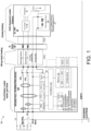
- the process 850 will be described with reference to the ground fault interrupting device 100 of FIG. 1 (e.g., 100), such as in the form of a circuit breaker, along with its components such as the controller(s) (e.g., 110) and sensors/monitors, etc.
- the process begins at block 852 in which the circuit breaker can monitor various energy-related (ER) signals and other signals related to the protected branch circuit, using a plurality of sensors/monitors including current sensors, voltage sensors, pilot monitor (or sensor), and so forth.
- the monitored signals can include energy-related signals, such as current, voltage, power, etc., across each line conductor(s), all line conductor(s), and all line conductors and the grounding conductor; as well as other signals such as a pilot signal, and so forth.
- the circuit breaker can perform ground fault detection and protection by analyzing the monitored energy-related signals, such as described herein.
- the circuit breaker interrupts the supply of power (e.g., power, current, voltage, etc.) to the branch circuit and load, thereby de-energizing the circuit and connected load, at block 862.
- the circuit breaker can also output a status notification such as a Ground Fault (GF) Alarm or type thereof, e.g., output locally through the user interface (e.g., via the I/O 140) or output to the user/user device or remote monitoring/management computer system).
- GF Ground Fault
- the circuit breaker can perform arc fault detection and protection for the branch circuit by analyzing the monitored energy-related signals, at block 870.
- the circuit breaker interrupts the supply of power (e.g., power, current, voltage, etc.) to the branch circuit and load, thereby de-energizing the circuit and connected load, at block 872.
- the circuit breaker can also output a status notification such as Arc Fault (AF) Alarm or type thereof, e.g., output locally through the user interface (e.g., via the I/O 140) or output to the user/user device or remote monitoring/management computer system).
- AF Arc Fault
- the circuit breaker can perform short-circuit fault detection and protection for the branch circuit by analyzing the monitored energy-related signals, at block 880.
- the circuit breaker interrupts the supply of power (e.g., power, current, voltage, etc.) to the branch circuit and load, thereby de-energizing the circuit and connected load, at block 882.
- the circuit breaker can also output a status notification such as Short-Circuit (SC) Fault Alarm or type thereof, e.g., output locally through the user interface (e.g., via the I/O 140) or output to the user/user device or remote monitoring/management computer system).
- SC Short-Circuit
- the circuit breaker can perform overcurrent fault detection and protection for the branch circuit and load by analyzing the monitored energy-related signals, at block 890.
- the circuit breaker interrupts the supply of power (e.g., power, current, voltage, etc.) to the branch circuit and load, thereby de-energizing the circuit and connected load, at block 892.
- the circuit breaker can also output a status notification such as Overcurrent (OC Fault Alarm or type thereof, e.g., output locally through the user interface (e.g., via the I/O 140) or output to the user/user device or remote monitoring/management computer system).
- OC Fault Alarm or type thereof, e.g., output locally through the user interface (e.g., via the I/O 140) or output to the user/user device or remote monitoring/management computer system.
- the circuit breaker can store and output (e.g., in real-time) monitored, derived and determined status and diagnostics for the electrical system, circuit breaker, branch circuit and load, at block 898. Such information can be output locally through the user interface (e.g., via the I/O 140) or output to the user/user device or remote monitoring/management computer system) for further analysis or action.
- the process 850 can thereafter proceed back to block 852 to continue the process.
- the process 850 describes examples of different types of faults or conditions (e.g., GF, AF, SCF, OCF, etc.), which can be detected and protected against by the circuit breaker or circuit protective device for the protected branch circuit and load.
- the circuit breaker or protective devices as described herein can be configured to perform any combination of ground fault detection and protection types in combination with any combination of other fault and/or condition detection and protection as described above.
- AF detection, OC fault detection and SC fault detection can be performed using conventional detection processes or algorithms, which may, for example, be used in conventional circuit breakers or circuit protection devices.
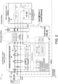
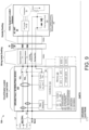
- FIG. 9 shows an example system environment 10A of a ground fault detection and protection system, such as a ground fault interrupting device 100A for use with an electrical system including HVAC (Heating, Ventilation, Air Conditioning) equipment in accordance with a second embodiment of the present disclosure.
- the components and functionality of the device 100A are the same or similar to that in the example device 100 of FIG. 1 , except that the device 100A does not include a first ground fault sensor GFS-1.
- the device 100A can detect for a ground fault due to excessive/abnormal leakage current from the load across the grounding conductor using the second ground fault sensor GFS-2, and for a ground fault due to improper connection of the grounding conductor using the pilot or ground monitor (Control Pilot).
- the allowable/acceptable range of leakage current for the load can be 15 mA to 20 mA.
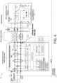
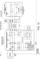
- FIG. 10 shows an example system environment 10B of a ground fault detection and protection system, such as a ground fault interrupting device 100B for use with an electrical system including HVAC (Heating, Ventilation, Air Conditioning) equipment in accordance with a third embodiment of the present disclosure.
- a ground fault interrupting device 100B for use with an electrical system including HVAC (Heating, Ventilation, Air Conditioning) equipment in accordance with a third embodiment of the present disclosure.
- HVAC Heating, Ventilation, Air Conditioning
- the device 100B can detect for a ground fault on the branch circuit or wiring thereof (e.g., ground fault between line conductors L1 or L2 and the Earth ground) using the first ground fault sensor GFS-1, and for an improper connection of the grounding conductor using the pilot or ground monitor (Control Pilot).
- the let-go level for the branch circuit can be in the range of 4 mA to 6 mA.
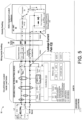
- FIG. 11 shows an example system environment 10C of a ground fault detection and protection system, such as a ground fault interrupting device 100C for use with an electrical system including HVAC (Heating, Ventilation, Air Conditioning) equipment in accordance with a fourth embodiment of the present disclosure.
- the components and functionality of the device 100C are the same or similar to that in the example device 100 of FIG. 1 , except that the device 100C does not include a second ground fault sensor GFS-2 and the pilot or ground monitor.
- the device 100B can detect for a ground fault on the branch circuit or wiring thereof (e.g., ground fault between line conductors L1 or L2 and the Earth ground) using the first ground fault sensor GFS-1.
- the let-go level for the branch circuit can be in the range of 4 mA to 6 mA.
- FIG. 12 shows an example system environment 10D of a ground fault detection and protection system, such as a ground fault interrupting device 100C for use with an electrical system including electrical equipment other than HVAC equipment in accordance with a fifth embodiment of the present disclosure.
- the components and functionality of the device 100D are the same or similar to that in the example device 100 of FIG. 1 , except that the device 100C is used to provide protection to a connected load, which is other than HVAC equipment.
- the load or equipment thereof can have an allowable, acceptable or normal leakage current level, which is higher or larger than the let-go current level of the branch circuit.
- FIG. 13 shows an example system environment 10E of a ground fault detection and protection system, such as a ground fault interrupting device 100E for use with an electrical system including HVAC (Heating, Ventilation, Air Conditioning) equipment in accordance with a sixth embodiment of the present disclosure.
- a ground fault interrupting device 100E for use with an electrical system including HVAC (Heating, Ventilation, Air Conditioning) equipment in accordance with a sixth embodiment of the present disclosure.
- the components and functionality of the device 100E are the same or similar to that in the example device 100 of FIG. 1 , except that the device 100E does not include the pilot or ground monitor.
- the device 100B can detect for a ground fault on the branch circuit or wiring thereof (e.g., ground fault between line conductors L1 or L2 and the Earth ground) using the first ground fault sensor GFS-1.
- the device 100E also can detect for a ground fault due to excessive/abnormal leakage current from the load across the grounding conductor using the second ground fault sensor GFS-2.
- the let-go level for the branch circuit can be in the range of 4 mA to 6 mA, and the allowable/acceptable range of leakage current for the load can be 15 mA to 20 mA.
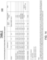
- FIG. 14 shows a chart 1400 in table form, which provides for the purposes of comparison example configurations, including detection levels or values, for different ground fault detection and protection scenarios. These scenarios include the scenario of a device implementing the current UL 943 Standard for Safety for GFCIs, as well as for the scenarios of the ground fault interrupting device 100, 100A, 100B, 100C, 100D and 100E of the first, second, third, fourth, and fifth embodiments respectively of the present disclosure.
- each scenario is shown with an associated configuration for the ground fault interrupting device, such as GF detection level for L1-GC, L2-GC, L1-E, L2-E where GC is the Grounding Conductor, E is Earth Ground, L1 is Ungrounded Conductor Line 1, and L2 is Ungrounded Conductor Line 2.
- the configuration also can include detection level related to Appliance Metallic Frame to Earth Ground (Appliance Metallic Frame-E), such as whether a Ground Monitor is provided and the Appliance Allowed leakage.
- the appliance metallic frame to earth allowable leakage current to earth can normally equal L1/L2 to allowable leakage current to earth without the ground monitor. With the ground monitor, the leakage current from the metallic frame to earth is close to zero since the ground monitor can make sure the impedance from the frame to earth is very low due to monitoring the grounding conductors and making sure the ground conductor impedance is low.
- FIG. 15 illustrates example components of a computer device (or system) 1500, in accordance with embodiments of the disclosure.
- the computer device 1500 can be a controller(s)/processor(s)-implemented fault interrupting device (e.g., ground fault interrupting device, circuit breaker, etc.), local or remote computer device or system (e.g., user device, central monitoring computer system, etc.) or other controller(s)/processor(s)-based device or system as described herein.
- a controller(s)/processor(s)-implemented fault interrupting device e.g., ground fault interrupting device, circuit breaker, etc.
- local or remote computer device or system e.g., user device, central monitoring computer system, etc.
- other controller(s)/processor(s)-based device or system as described herein e.g., user device, central monitoring computer system, etc.
- the device 1500 can include memory 1510, processor(s) 1520, communication device(s) 1530, clock 1540, input/output device(s) 1550, which can be communicatively connected.
- the various components can be communicatively connected via buses 1570.
- the clock 1540 can be used to time-stamp data or an event with a time value, and to synchronize operations within the device and with remote devices or systems.
- the communication device(s) 1530 can include transmitters and receivers for conducting wireless communications and/or wireline communications with other remote devices or a network(s).
- the memory 1510 can store computer executable code, programs, software, or instructions, which when executed by a processor(s), controls the operations of the device 1500, including the various processes/algorithms described herein.
- the memory 1510 can also store other data used by the device 1500 or components thereof to perform the operations described herein.
- the other data can include but is not limited to threshold (or level) values or ranges, diagnostic information, status information, alarm information, and other information as described herein.
- the processor(s) 1520 which interacts with the other components of the computer device, is configured to control or implement the various operations and functions described herein, including control of the components of the computer device 1500 and quality analysis of a network installation.
- the input/output device(s) 1550 can include one or more input devices, and one or more output devices.
- the input devices can include a handle, button(s), keyboard, keypad, touch panel or screen, microphone, camera or other known user input devices for use on computer devices or systems, including controller/processor-based circuit protective devices such as fault interrupting devices, miniature circuit breakers and other devices or systems as described herein.
- the output devices can include a display screen, speaker, printer, smart output device, LED(s), handle positions, or other known output devices in or for use with computer devices or systems, including controller/processor-based circuit protective devices such as fault interrupting devices, miniature circuit breakers, and other devices or systems as described herein.
- the sensor(s) 1560 can include one or more sensors for monitoring energy-related signals on the conductors (e.g., line conductor(s), grounding conductor(s), pilot signal wire, etc.), including those described herein.
- the sensor(s) 1560 can include current sensor(s), voltage sensor(s), power sensor(s), ground fault sensor(s) for measuring different combination of conductor(s) (e.g., line conductor(s) and/or grounding conductor (including neutral-ground, etc.), etc.), pilot signal sensor or other types of sensors (including those described herein) for sensing energy-related signals to perform diagnostics on an electrical system including its circuit(s) and load(s).
- the computer device 1500 can include or not include various components as shown in the example of FIG. 15 , or can include additional components.
- embodiments of the disclosure herein may be configured as a system, method, or combination thereof. Accordingly, embodiments of the present disclosure may be comprised of various means including hardware, software, firmware or any combination thereof.
- example embodiments may be implemented as a machine, process, or article of manufacture by using standard programming and/or engineering techniques to produce programming software, firmware, hardware, or any combination thereof.
- Any resulting program(s), having computer-readable program code, may be embodied on one or more tangible or non-transitory computer-usable media such as resident memory devices, smart cards or other removable memory devices, or transmitting devices, thereby making a computer program product or article of manufacture according to the embodiments.
- the terms "article of manufacture” and “computer program product” as used herein are intended to encompass a computer program that exists permanently or temporarily on any computer-usable or storage medium or in any transmitting medium which transmits such a program.
- a processor(s), controller(s) or processing unit(s) as described herein can be a processing system, which can include one or more processors, such as CPU, controllers, ASICs, or other processing units or circuitry, which controls or performs the operations of the devices or systems, described herein.
- Memory/storage devices can include, but are not limited to, disks, solid state drives, optical disks, removable memory devices such as smart cards, SIMs, WIMs, semiconductor memories such as RAM, ROM, PROMS, etc.
- Transmitting mediums or networks can include, but are not limited to, transmission via wireline communication, wireless communication (e.g., Radio Frequency (RF) communication, Bluetooth ® , Wi-Fi, Li-Fi, etc.), the Internet, intranets, telephone/modem-based network communication, hard-wired/cabled communication network, satellite communication, and other stationary or mobile network systems/communication links.
- wireless communication e.g., Radio Frequency (RF) communication, Bluetooth ® , Wi-Fi, Li-Fi, etc.
- the Internet intranets
- telephone/modem-based network communication e.g., hard-wired/cabled communication network
- satellite communication e.g., satellite communication, and other stationary or mobile network systems/communication links.
- each block in the flowchart or block diagrams may represent a module, segment or portion of code, which comprises one or more executable instructions for implementing the specified logical function(s).
- the functions noted in the block may occur out of the order noted in the figures. For example, two blocks shown in succession may, in fact, be executed substantially concurrently, or the blocks may sometimes be executed in the reverse order, depending upon the functionality involved.
Landscapes
- Physics & Mathematics (AREA)
- General Physics & Mathematics (AREA)
- Engineering & Computer Science (AREA)
- Power Engineering (AREA)
- Emergency Protection Circuit Devices (AREA)
- Testing Of Short-Circuits, Discontinuities, Leakage, Or Incorrect Line Connections (AREA)
Applications Claiming Priority (1)
| Application Number | Priority Date | Filing Date | Title |
|---|---|---|---|
| US18/375,347 US12548994B2 (en) | 2023-09-29 | 2023-09-29 | Ground fault interrupting system for HVAC equipment |
Publications (1)
| Publication Number | Publication Date |
|---|---|
| EP4531220A1 true EP4531220A1 (de) | 2025-04-02 |
Family
ID=92633975
Family Applications (1)
| Application Number | Title | Priority Date | Filing Date |
|---|---|---|---|
| EP24198002.8A Pending EP4531220A1 (de) | 2023-09-29 | 2024-09-02 | Erdschlussunterbrechungssystem für hlk-geräte |
Country Status (3)
| Country | Link |
|---|---|
| US (1) | US12548994B2 (de) |
| EP (1) | EP4531220A1 (de) |
| CN (1) | CN119742714A (de) |
Citations (5)
| Publication number | Priority date | Publication date | Assignee | Title |
|---|---|---|---|---|
| US5793587A (en) * | 1997-08-18 | 1998-08-11 | Hubbell Incorporated | Dual trip level ground fault interrupter |
| EP0866535A2 (de) * | 1997-03-21 | 1998-09-23 | Werner Elischer | Fehlerstromschutzschalter fuer Stromkreise mit hohen Fehlerströmen |
| CN2938688Y (zh) * | 2006-08-29 | 2007-08-22 | 张凤林 | 一种矿用照明综合保护装置 |
| US20070208520A1 (en) * | 2006-03-01 | 2007-09-06 | Siemens Energy & Automation, Inc. | Systems, devices, and methods for arc fault management |
| US20080212244A1 (en) * | 2006-10-19 | 2008-09-04 | Mario Bilac | Electronic breaker system |
Family Cites Families (1)
| Publication number | Priority date | Publication date | Assignee | Title |
|---|---|---|---|---|
| US20140211345A1 (en) * | 2013-01-30 | 2014-07-31 | Eaton Corporation | Annunciating or power vending circuit breaker for an electric load |
-
2023
- 2023-09-29 US US18/375,347 patent/US12548994B2/en active Active
-
2024
- 2024-09-02 EP EP24198002.8A patent/EP4531220A1/de active Pending
- 2024-09-27 CN CN202411360347.7A patent/CN119742714A/zh active Pending
Patent Citations (5)
| Publication number | Priority date | Publication date | Assignee | Title |
|---|---|---|---|---|
| EP0866535A2 (de) * | 1997-03-21 | 1998-09-23 | Werner Elischer | Fehlerstromschutzschalter fuer Stromkreise mit hohen Fehlerströmen |
| US5793587A (en) * | 1997-08-18 | 1998-08-11 | Hubbell Incorporated | Dual trip level ground fault interrupter |
| US20070208520A1 (en) * | 2006-03-01 | 2007-09-06 | Siemens Energy & Automation, Inc. | Systems, devices, and methods for arc fault management |
| CN2938688Y (zh) * | 2006-08-29 | 2007-08-22 | 张凤林 | 一种矿用照明综合保护装置 |
| US20080212244A1 (en) * | 2006-10-19 | 2008-09-04 | Mario Bilac | Electronic breaker system |
Also Published As
| Publication number | Publication date |
|---|---|
| US12548994B2 (en) | 2026-02-10 |
| US20250112451A1 (en) | 2025-04-03 |
| CN119742714A (zh) | 2025-04-01 |
Similar Documents
| Publication | Publication Date | Title |
|---|---|---|
| US12244134B2 (en) | Device and method for detecting faulty electrical circuits with fault identification and alert system | |
| CA2921338C (en) | Distributed arc fault protection between outlet and circuit breaker | |
| AU2014224084B2 (en) | Electrical control and protection device | |
| US12571855B2 (en) | Circuit breakers with notification and reporting capability | |
| CN111226366A (zh) | 用于自适应ac/dc浪涌保护的方法和设备 | |
| KR102471911B1 (ko) | 지능형 전기화재 예측 감시제어시스템 및 이를 이용한 전기화재 예측 감시제어방법 | |
| RU2483411C2 (ru) | Способ и устройство защиты для контроля сборных шин электрической сети энергоснабжения | |
| KR100906304B1 (ko) | 서지전압 보호회로의 누설전류 차단제어장치 | |
| WO2018131797A1 (ko) | 배전계통 전원선로 고장시 실시간 탐지/복구시스템 및 그 공사방법 | |
| US9728955B2 (en) | Zone selective interlocking (ZSI) power distribution operating a ZSI power distribution system | |
| KR102415477B1 (ko) | 전기고장 감지 관리장치 | |
| CN104718679A (zh) | 用于电弧事件保护的全双工信令 | |
| US20140330531A1 (en) | Network monitoring apparatus and network monitoring method | |
| CN104600658B (zh) | 电力分配系统和测试电力分配系统的方法 | |
| CN102067399A (zh) | 电气安装系统 | |
| US20090257156A1 (en) | Method of setting a ground fault trip function for a trip unit and a trip unit having a defined trip function for ground fault protection | |
| US12548994B2 (en) | Ground fault interrupting system for HVAC equipment | |
| KR101049862B1 (ko) | 중성선 대체기능이 구비된 분배전반 | |
| KR101030193B1 (ko) | 중성선 대체기능이 구비된 분배전반 및 그 분배전반의 중성선 대체방법 | |
| AU2020227109A1 (en) | Auxiliary electronic protection module and associated breaker device | |
| CN119742716A (zh) | 用于hvac设备插座断开的接地故障中断 | |
| US12592554B2 (en) | Centralized fault detection with fault recovery system and method | |
| KR101623759B1 (ko) | 수배전반의 기중 차단기 제어 시스템 및 방법 | |
| JP7785426B2 (ja) | 放電検出装置 | |
| US20240192285A1 (en) | Method and apparatus for smart centralized arc fault detection in a system |
Legal Events
| Date | Code | Title | Description |
|---|---|---|---|
| PUAI | Public reference made under article 153(3) epc to a published international application that has entered the european phase |
Free format text: ORIGINAL CODE: 0009012 |
|
| STAA | Information on the status of an ep patent application or granted ep patent |
Free format text: STATUS: THE APPLICATION HAS BEEN PUBLISHED |
|
| AK | Designated contracting states |
Kind code of ref document: A1 Designated state(s): AL AT BE BG CH CY CZ DE DK EE ES FI FR GB GR HR HU IE IS IT LI LT LU LV MC ME MK MT NL NO PL PT RO RS SE SI SK SM TR |
|
| STAA | Information on the status of an ep patent application or granted ep patent |
Free format text: STATUS: REQUEST FOR EXAMINATION WAS MADE |
|
| 17P | Request for examination filed |
Effective date: 20250925 |