EP4531233A1 - Verfahren und vorrichtung zur leistungsverwaltung in einer solarbetriebenen elektronischen vorrichtung - Google Patents
Verfahren und vorrichtung zur leistungsverwaltung in einer solarbetriebenen elektronischen vorrichtung Download PDFInfo
- Publication number
- EP4531233A1 EP4531233A1 EP24183716.0A EP24183716A EP4531233A1 EP 4531233 A1 EP4531233 A1 EP 4531233A1 EP 24183716 A EP24183716 A EP 24183716A EP 4531233 A1 EP4531233 A1 EP 4531233A1
- Authority
- EP
- European Patent Office
- Prior art keywords
- solar panel
- voltage
- switch
- negative terminal
- electronic device
- Prior art date
- Legal status (The legal status is an assumption and is not a legal conclusion. Google has not performed a legal analysis and makes no representation as to the accuracy of the status listed.)
- Pending
Links
Images




Classifications
-
- H—ELECTRICITY
- H02—GENERATION; CONVERSION OR DISTRIBUTION OF ELECTRIC POWER
- H02J—ELECTRIC POWER NETWORKS; CIRCUIT ARRANGEMENTS OR SYSTEMS FOR SUPPLYING OR DISTRIBUTING ELECTRIC POWER; SYSTEMS FOR STORING ELECTRIC ENERGY
- H02J7/00—Circuit arrangements for charging or discharging batteries or for supplying loads from batteries
- H02J7/34—Parallel operation in networks using both storage and other DC sources, e.g. providing buffering
-
- H—ELECTRICITY
- H02—GENERATION; CONVERSION OR DISTRIBUTION OF ELECTRIC POWER
- H02J—ELECTRIC POWER NETWORKS; CIRCUIT ARRANGEMENTS OR SYSTEMS FOR SUPPLYING OR DISTRIBUTING ELECTRIC POWER; SYSTEMS FOR STORING ELECTRIC ENERGY
- H02J7/00—Circuit arrangements for charging or discharging batteries or for supplying loads from batteries
- H02J7/34—Parallel operation in networks using both storage and other DC sources, e.g. providing buffering
- H02J7/35—Parallel operation in networks using both storage and other DC sources, e.g. providing buffering with light sensitive cells
-
- H—ELECTRICITY
- H02—GENERATION; CONVERSION OR DISTRIBUTION OF ELECTRIC POWER
- H02J—ELECTRIC POWER NETWORKS; CIRCUIT ARRANGEMENTS OR SYSTEMS FOR SUPPLYING OR DISTRIBUTING ELECTRIC POWER; SYSTEMS FOR STORING ELECTRIC ENERGY
- H02J7/00—Circuit arrangements for charging or discharging batteries or for supplying loads from batteries
- H02J7/40—Circuit arrangements for charging or discharging batteries or for supplying loads from batteries characterised by the exchange of charge or discharge related data
- H02J7/443—Circuit arrangements for charging or discharging batteries or for supplying loads from batteries characterised by the exchange of charge or discharge related data using passive battery identification means, e.g. resistors or capacitors
-
- H—ELECTRICITY
- H02—GENERATION; CONVERSION OR DISTRIBUTION OF ELECTRIC POWER
- H02J—ELECTRIC POWER NETWORKS; CIRCUIT ARRANGEMENTS OR SYSTEMS FOR SUPPLYING OR DISTRIBUTING ELECTRIC POWER; SYSTEMS FOR STORING ELECTRIC ENERGY
- H02J7/00—Circuit arrangements for charging or discharging batteries or for supplying loads from batteries
- H02J7/60—Circuit arrangements for charging or discharging batteries or for supplying loads from batteries including safety or protection arrangements
- H02J7/663—Circuit arrangements for charging or discharging batteries or for supplying loads from batteries including safety or protection arrangements using battery or load disconnect circuits
- H02J7/667—Circuit arrangements for charging or discharging batteries or for supplying loads from batteries including safety or protection arrangements using battery or load disconnect circuits disconnection of loads if battery is not under charge, e.g. in vehicle if engine is not running
-
- H—ELECTRICITY
- H02—GENERATION; CONVERSION OR DISTRIBUTION OF ELECTRIC POWER
- H02J—ELECTRIC POWER NETWORKS; CIRCUIT ARRANGEMENTS OR SYSTEMS FOR SUPPLYING OR DISTRIBUTING ELECTRIC POWER; SYSTEMS FOR STORING ELECTRIC ENERGY
- H02J7/00—Circuit arrangements for charging or discharging batteries or for supplying loads from batteries
- H02J7/60—Circuit arrangements for charging or discharging batteries or for supplying loads from batteries including safety or protection arrangements
- H02J7/685—Circuit arrangements for charging or discharging batteries or for supplying loads from batteries including safety or protection arrangements using connection detecting circuits
-
- H—ELECTRICITY
- H02—GENERATION; CONVERSION OR DISTRIBUTION OF ELECTRIC POWER
- H02J—ELECTRIC POWER NETWORKS; CIRCUIT ARRANGEMENTS OR SYSTEMS FOR SUPPLYING OR DISTRIBUTING ELECTRIC POWER; SYSTEMS FOR STORING ELECTRIC ENERGY
- H02J7/00—Circuit arrangements for charging or discharging batteries or for supplying loads from batteries
- H02J7/80—Circuit arrangements for charging or discharging batteries or for supplying loads from batteries including monitoring or indicating arrangements
-
- H—ELECTRICITY
- H02—GENERATION; CONVERSION OR DISTRIBUTION OF ELECTRIC POWER
- H02J—ELECTRIC POWER NETWORKS; CIRCUIT ARRANGEMENTS OR SYSTEMS FOR SUPPLYING OR DISTRIBUTING ELECTRIC POWER; SYSTEMS FOR STORING ELECTRIC ENERGY
- H02J7/00—Circuit arrangements for charging or discharging batteries or for supplying loads from batteries
- H02J7/90—Regulation of charging or discharging current or voltage
- H02J7/933—Regulation of charging or discharging current or voltage the cycle being controlled or terminated in response to electric parameters
-
- H—ELECTRICITY
- H02—GENERATION; CONVERSION OR DISTRIBUTION OF ELECTRIC POWER
- H02J—ELECTRIC POWER NETWORKS; CIRCUIT ARRANGEMENTS OR SYSTEMS FOR SUPPLYING OR DISTRIBUTING ELECTRIC POWER; SYSTEMS FOR STORING ELECTRIC ENERGY
- H02J7/00—Circuit arrangements for charging or discharging batteries or for supplying loads from batteries
- H02J7/90—Regulation of charging or discharging current or voltage
- H02J7/96—Regulation of charging or discharging current or voltage in response to battery voltage
-
- H—ELECTRICITY
- H02—GENERATION; CONVERSION OR DISTRIBUTION OF ELECTRIC POWER
- H02J—ELECTRIC POWER NETWORKS; CIRCUIT ARRANGEMENTS OR SYSTEMS FOR SUPPLYING OR DISTRIBUTING ELECTRIC POWER; SYSTEMS FOR STORING ELECTRIC ENERGY
- H02J2101/00—Supply or distribution of decentralised, dispersed or local electric power generation
- H02J2101/20—Dispersed power generation using renewable energy sources
- H02J2101/22—Solar energy
- H02J2101/24—Photovoltaics
Definitions
- a method in an electronic device comprising a power management subsystem , a controller, and a plurality of peripherals, the electronic device powered by a solar panel and a rechargeable battery both connected at respective positive terminals thereof to the controller and the plurality of peripherals.
- the method comprises determining whether the solar panel is connected at a negative terminal thereof to a ground terminal and in response to determining that the solar panel is connected at the negative terminal thereof to the ground terminal, disconnecting the negative terminal from the ground terminal.
- the method further comprises reading a voltage at the negative terminal of the solar panel and in response to determining based on the voltage that the solar panel is generating sufficient electrical energy to power at least some of the plurality of peripherals, connecting the negative terminal of the solar panel to the ground terminal.
- the negative terminal of the solar panel is connected with the ground terminal via an N-channel Field Effect Transistor (NFET) switch having a source, a gate, and a drain.
- NFET Field Effect Transistor
- the NFET switch is connected at the source thereof to the ground terminal and connected at the drain thereof to the negative terminal of the solar panel and determining that the solar panel is not generating sufficient energy comprises detecting a positive voltage at the drain of the NFET switch.
- determining that the solar panel is not generating sufficient energy is done without connecting the negative terminal of the solar panel to the ground. This prevents draining of the rechargeable battery through the solar panel during the determining.
- the negative terminal of the solar panel is connected with the ground terminal via a P-channel Field Effect Transistor (PFET) switch having a source, a gate, and a drain.
- PFET Field Effect Transistor
- the PFET switch is connected at the drain thereof to the ground terminal and connected at the source thereof to the negative terminal of the solar panel, and determining that the solar panel is not generating sufficient energy comprises detecting a positive voltage at the source of the PFET switch.
- determining that the solar panel is not generating sufficient energy is done without connecting the negative terminal of the solar panel to the ground. This prevents draining of the rechargeable battery through the solar panel during the determining.
- the negative terminal of the solar panel is connected with the ground terminal via a Field Effect Transistor (FET) switch and connecting the negative terminal with the ground terminal comprises closing the FET switch.
- FET Field Effect Transistor
- reading the voltage at the negative terminal of the solar panel comprises enabling a voltage sensor connected to the negative terminal of the solar panel and reading a voltage sensor signal of the voltage sensor.
- the voltage sensor is enabled only when necessary to determine whether the solar panel is generating sufficient energy and is otherwise disabled. Keeping the voltage sensor disabled most of the time saves electric energy.
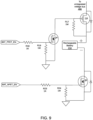
- the voltage sensor comprises an operational amplifier having an inverting input, a non-inverting input, a positive supply terminal, a negative supply terminal, and an output.
- the negative supply terminal is connected with the negative terminal of the solar panel
- the output of the operational amplifier is connected to the inverting input
- the non-inverting input of the operational amplifier is connected to ground.
- Enabling the voltage sensor comprises asserting, by the controller, a voltage sensor enable signal connected to the positive supply terminal of the operational amplifier.
- This implementation of the voltage sensor has the advantage of measuring a voltage at the negative supply terminal of the solar panel that may be either positive or negative, while providing a voltage sensor signal that is always positive and thus is suitable for conversion to a digital value by an analog to digital converter, for example.
- the voltage sensor signal of the voltage sensor comprises a positive analog signal and reading the voltage sensor signal of the voltage sensor comprises converting the positive analog signal to a digital value.
- the digital value can be compared with particular values in firmware and used to decide whether to reconnect the solar panel or keep it disconnected.
- an electronic device comprising a controller, a memory coupled to the controller, and a plurality of peripherals. Additionally, the electronic device comprises a solar panel coupled to the controller, the memory, and the plurality of peripherals. The electronic device further comprises a rechargeable battery coupled to the controller, to the memory, to the plurality of peripherals, and to the solar panel. Furthermore, the electronic device comprises a power management subsystem coupled to the solar panel and to the rechargeable battery, the power management subsystem including a voltage sensor connected with a negative terminal of the solar panel and a solar panel bottom switch connected with the negative terminal of the solar panel.
- the memory stores machine-executable programming instructions which configure the electronic device to determine whether the solar panel is connected at a negative terminal thereof to a ground terminal via the solar panel bottom switch. In response to determining that the solar panel is connected at the negative terminal thereof to the ground terminal, the machine-executable programming instructions configure the electronic device to disconnect the negative terminal from the ground terminal. The machine-executable programming instructions further configure the electronic device to read a voltage at the negative terminal of the solar panel. In response to determining, based on the voltage, that the solar panel is generating sufficient electrical energy to power at least some of the plurality of peripherals, the machine-executable programming instructions configure the electronic device to connect the negative terminal of the solar panel with the ground terminal.
- the machine-executable programming instructions further configure the electronic device to read a voltage at the negative terminal of the solar panel. In response to determining, based on the voltage, that the solar panel is not generating sufficient electrical energy to power at least some of the plurality of peripherals, the machine-executable programming instructions configure the electronic device to keep the negative terminal of the solar panel disconnected from the ground terminal.
- the solar panel bottom switch comprises an N-channel Field Effect Transistor (NFET) switch having a source, a gate, and a drain.
- NFET Field Effect Transistor
- the NFET switch is connected at the source thereof to the ground terminal and connected at the drain thereof to the negative terminal of the solar panel, and the machine-executable programming instructions which configure the electronic device to determine that the solar panel is generating sufficient energy comprise machine-executable programming instructions which detect a negative voltage at the drain of the NFET switch.
- the solar panel bottom switch comprises a P-channel Field Effect Transistor (PFET) switch having a source, a gate, and a drain.
- PFET Field Effect Transistor
- the PFET switch is connected at the drain thereof to the ground terminal and connected at the source thereof to the negative terminal of the solar panel, and the machine-executable programming instructions which determine that the solar panel is generating sufficient energy comprise machine-executable programming instructions which configure the electronic device to detect a negative voltage at the source of the PFET switch.
- the solar panel bottom switch comprises an N-channel Field Effect Transistor (NFET) switch having a source, a gate, and a drain.
- NFET Field Effect Transistor
- the NFET switch is connected at the source thereof to the ground terminal and connected at the drain thereof to the negative terminal of the solar panel, and the machine-executable programming instructions which configure the electronic device to determine that the solar panel is not generating sufficient energy comprise machine-executable programming instructions which configure the electronic device to detect a positive voltage at the drain of the NFET switch.
- solar panel bottom switch comprises a P-channel Field Effect Transistor (PFET) switch having a source, a gate, and a drain.
- PFET Field Effect Transistor
- the PFET switch is connected at the drain thereof to the ground terminal and connected at the source thereof to the negative terminal of the solar panel, and the machine-executable programming instructions which determine that the solar panel is not generating sufficient energy comprise machine-executable programming instructions which configure the electronic device to detect a positive voltage at the source of the PFET switch.
- the solar panel bottom switch comprises a Field Effect Transistor (FET) switch and the machine-executable programming instructions which configure the electronic device to connect the negative terminal with to the ground terminal comprise machine-executable programming instructions which close the FET switch.
- FET Field Effect Transistor
- the machine-executable programming instructions which configure the electronic device to read the voltage at the negative terminal of the solar panel comprise machine-executable programming instructions which configure the electronic device to enable the voltage sensor I and read a voltage sensor signal of the voltage sensor.
- the voltage sensor comprises an operational amplifier having an inverting input, a non-inverting input, a positive supply terminal, a negative supply terminal, and an output.
- the negative supply terminal is connected to the negative terminal of the solar panel
- the output of the operational amplifier is connected to the inverting input thereof
- the voltage sensor signal of the voltage sensor is the output of the operational amplifier
- the non-inverting input of the operational amplifier is connected to ground
- the machine-executable programming instructions which configure the electronic device to enable the voltage sensor comprise the machine-executable programming instructions which configure the electronic device to assert, by the controller, a signal connected to the positive supply terminal of the operational amplifier.
- the voltage sensor signal of the voltage sensor comprises a positive analog signal and the machine-executable programming instructions which configure the electronic device to read the voltage sensor signal of the voltage sensor comprise machine-executable programming instructions which configure the electronic device to convert the positive analog signal to a digital value.
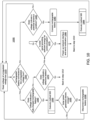
- a method in an electronic device comprising a power management subsystem, a controller, and a plurality of peripherals, the electronic device powered by a solar panel and a rechargeable battery both connected at respective positive terminals thereof with the controller and the plurality of peripherals via an unregulated voltage bus.
- the method comprises reading a voltage of the unregulated voltage bus.
- the method further comprises disconnecting the rechargeable battery from the unregulated voltage bus.
- the rechargeable battery is not repeatedly and unnecessarily being discharged and recharged when it is already fully charged. This prolongs the battery life.
- determining that the solar panel provides sufficient electric energy comprises disconnecting the negative terminal of the solar panel from a ground terminal and detecting by a voltage sensor a negative voltage at the negative terminal of the solar panel.
- the voltage sensor comprises an operational amplifier having an inverting input, a non-inverting input, a positive supply terminal, a negative supply terminal, and an output.
- the negative supply terminal is connected to the negative terminal of the solar panel
- the output of the operational amplifier is connected to the inverting input
- a voltage sensor signal of the voltage sensor is the output of the operational amplifier
- the non-inverting input of the operational amplifier is connected to ground
- enabling the voltage sensor comprises asserting by the controller a signal connected to the positive supply terminal of the operational amplifier.
- the voltage sensor signal of the voltage sensor comprises a positive analog signal and reading the voltage sensor signal of the voltage sensor comprises converting the positive analog signal to a digital value.
- the negative terminal of the solar panel is connected with a ground terminal via an N-channel Field Effect Transistor (NFET) switch having a source, a gate, and a drain.
- NFET Field Effect Transistor
- the NFET switch is connected at the source thereof to the ground terminal and connected at the drain thereof to the negative terminal of the solar panel, and determining that the solar panel is generating sufficient energy comprises detecting a negative voltage at the drain of the NFET switch.
- disconnecting the rechargeable battery from the unregulated voltage bus comprises opening a top battery switch between a positive terminal of the rechargeable battery and the unregulated voltage bus and opening a bottom battery switch between a negative terminal of the rechargeable battery and a ground terminal.
- the method further comprises in response to determining that the rechargeable battery is connected to the unregulated voltage bus and in response to determining, based on the voltage of the unregulated voltage bus, that the rechargeable battery is defective, and in response to determining that the solar panel provides sufficient electric energy to power up a network interface of the electronic device, the method further comprises powering up the network interface and sending a notification to a remote server indicating that the rechargeable battery is defective.
- the method further comprises in response to determining that the rechargeable battery is disconnected from the unregulated voltage bus and in response to determining that a potential brownout condition based on the voltage of the unregulated voltage bus, connecting the rechargeable battery to the unregulated voltage bus.
- the method in response to determining that the rechargeable battery is disconnected from the unregulated voltage bus and in response to determining that a potential brownout condition based on the voltage of the unregulated voltage bus, and in response to determining that the solar panel is not generating sufficient electric energy, the method further includes disconnecting the solar panel at the negative terminal thereof from a ground terminal.
- the negative terminal of the solar panel is connected with the ground terminal via an N-channel Field Effect Transistor (NFET) switch having a source, a gate, and a drain.
- the NFET switch is connected at the source thereof to the ground terminal and connected at the drain thereof to the negative terminal of the solar panel and determining that the solar panel is not generating sufficient energy comprises detecting a positive voltage at the drain of the NFET switch.
- NFET Field Effect Transistor
- an electronic device comprising a controller; a memory coupled to the controller; a plurality of peripherals coupled to the controller; an unregulated voltage bus; a rechargeable battery for providing power to the controller, the memory, and the plurality of peripherals via the unregulated voltage bus; a solar panel for recharging the rechargeable battery and for providing power to the controller, the memory, and the plurality of peripherals via the unregulated voltage bus; and a power management subsystem coupled to the controller, the rechargeable battery, and the solar panel.
- the memory stores machine-executable programming instructions which when executed by the controller configures the electronic device to read a voltage of the unregulated voltage bus.
- the machine-executable programming instructions configure the electronic device to disconnect the rechargeable battery from the unregulated voltage bus.
- the machine-executable programming instructions which configure the electronic device to determine that the solar panel provides sufficient electric energy comprise machine-executable programming instructions which configure the electronic device to disconnect the negative terminal of the solar panel from a ground terminal and detect, by a voltage sensor, a negative voltage at the negative terminal of the solar panel.
- the voltage sensor comprises an operational amplifier having an inverting input, a non-inverting input, a positive supply terminal, a negative supply terminal, and an output.
- the negative supply terminal is connected to the negative terminal of the solar panel
- the output of the operational amplifier is connected to the inverting input
- a voltage sensor signal of the voltage sensor is the output of the operational amplifier
- the non-inverting input of the operational amplifier is connected to ground
- the machine-executable programming instructions which configure the electronic device to enable the voltage sensor comprise machine-executable programming instructions which configure the electronic device to assert by the controller a signal connected to the positive supply terminal of the operational amplifier.
- the voltage sensor signal of the voltage sensor comprises a positive analog signal and the machine-executable programming instructions which configure the electronic device to read the voltage sensor signal of the voltage sensor comprise machine-executable which configure the electronic device to convert the positive analog signal to a digital value.
- the negative terminal of the solar panel is connected with a ground terminal via an N-channel Field Effect Transistor (NFET) switch having a source, a gate, and a drain.
- NFET Field Effect Transistor
- the NFET switch is connected at the source thereof to the ground terminal and connected at the drain thereof to the negative terminal of the solar panel and the machine-executable programming instructions which configure the electronic device to determine that the solar panel is generating sufficient energy comprise machine-executable programming instructions which configure the electronic device to detect a negative voltage at the drain of the NFET switch.
- the machine-executable programming instructions which configure the electronic device to disconnect the rechargeable battery from the unregulated voltage bus comprise machine-executable programming instructions which configure the electronic device to open a top battery switch between a positive terminal of the rechargeable battery and the unregulated voltage bus and open a bottom battery switch between a negative terminal of the rechargeable battery and a ground terminal.
- the machine-executable programming instructions further configure the electronic device in response to determining that the rechargeable battery is connected to the unregulated voltage bus, in response to determining based on the voltage of the unregulated voltage bus that the rechargeable battery is defective, and in response to determining that the solar panel provides sufficient electric energy, to power up the network interface and send a notification to a remote server indicating that the rechargeable battery is defective.
- the machine-executable programming instructions further configure the electronic device to connect the rechargeable battery to the unregulated voltage bus in response to determining that the rechargeable battery is disconnected from the unregulated voltage bus and in response to determining that a potential brownout condition based on the voltage of the unregulated voltage bus.
- the machine-executable programming instructions further configure the electronic device in response to determining that the rechargeable battery is disconnected from the unregulated voltage bus, in response to determining that a potential brownout condition based on the voltage of the unregulated voltage bus, and in response to determining that the solar panel is not generating sufficient electric energy, to disconnect the solar panel at the negative terminal thereof from a ground terminal.
- the negative terminal of the solar panel is connected with the ground terminal via an N-channel Field Effect Transistor (NFET) switch having a source, a gate, and a drain.
- NFET Field Effect Transistor
- the NFET switch is connected at the source thereof to the ground terminal and connected at the drain thereof to the negative terminal of the solar panel and the machine-executable programming instructions which configure the electronic device to determine that the solar panel is not generating sufficient energy comprise machine-executable programming instructions which configure the electronic device to detect a positive voltage at the drain of the NFET switch.
- the present disclosure relates generally to solar-powered electronic devices powered by a rechargeable battery and a solar panel. More specifically, the present disclosure provides a power management module for a solar-powered electronic device.
- the power management module uses a combination of discrete electronic components and firmware to manage the operation and configuration of both the rechargeable battery and the solar panel. Additionally, the present disclosure provides methods for power management of a solar-powered electronic device.
- An asset tracker is an electronic device deployed in an asset for tracking the location and condition thereof.
- An asset tracker is typically part of an asset tracking system.
- An asset tracking system allows an administrator to track the location and condition of one or more than one assets.
- An asset may be a vehicle, a piece of equipment, a shipping container, a trailer, a tank, or any other type of asset whose location and condition need to be tracked.
- the power management module and the method for power management of a solar-powered electronic device presented in this disclosure are not, however, limited by such embodiment.
- the solar-powered electronic device discussed in this disclosure is an electronic device that can practically operate off of a rechargeable battery and/or a solar panel.
- a solar-powered electronic device include, but are not limited to, an asset tracker; a communication and signal booster such as a Wireless Fidelity (Wi-Fi) extender or a cellular signal booster; an electronic weather station including rain gauges, temperature sensors, anemometers, and barometers; an electronic wireless surveillance system including cameras, motion sensors, and communication modules; a ventilation system, such as attic fans and ventilation systems for vehicles; and any other electronic device that utilizes both a solar panel and a rechargeable battery.
- a communication and signal booster such as a Wireless Fidelity (Wi-Fi) extender or a cellular signal booster
- Wi-Fi Wireless Fidelity
- an electronic weather station including rain gauges, temperature sensors, anemometers, and barometers
- an electronic wireless surveillance system including cameras, motion sensors, and communication modules
- a ventilation system such as attic fans and
- a "solar panel” refers to a portable solar panel suitable for use with an electronic device, not large solar panels typically installed on building rooftops.
- a portable solar panel is a compact and lightweight energy harvesting device that converts sunlight into electrical energy by using photovoltaic cells. Photovoltaic cells are made of materials that generate electrons when exposed to light.
- a portable solar panel is designed to provide a convenient and renewable power source for various portable electronic devices, such as a solar-powered asset tracker. The electric energy generated by the solar panel may be used to charge a rechargeable battery and/or power the various components of a solar-powered asset tracker, as will be described in detail below.
- Common types of portable solar panels for portable electronic devices include monocrystalline solar panels, polycrystalline solar panels, and thin-film solar panels.
- Monocrystalline solar panels use a single silicon crystal per photovoltaic cell, while polycrystalline solar panels use multiple silicon crystals melted together per photovoltaic cell.
- Thin-film solar cells are made by depositing one or more thin layers of photovoltaic material onto a substrate, such as glass, plastic, or metal.
- a rechargeable battery is a type of battery that can be charged and discharged multiple times making it reusable. Rechargeable batteries can be recharged, using electrical energy, to restore their energy storage capacity for future use.
- a rechargeable battery may be of any of the following types of rechargeable batteries: Nickel-Cadmium (Ni-Cd), Nickel-Metal Hydride (NiMH), Lithium-Ion (Li-ion), or Lithium Polymer (LiPo).
- Ni-Cd batteries are less common since they have a relatively low energy density compared to other rechargeable battery types, and because they suffer from the memory effect.
- NiMH batteries have better energy density than Ni-Cd batteries but still suffer from the memory effect.
- Li-ion batteries are widely used as they have a higher energy density than Ni-Cd and NiMH, and have no memory effect.
- Variants of Li-ion batteries include Lithium Cobalt Oxide (LiCoO2), Lithium Iron Phosphate (LiFePO4), Lithium Nickel Manganese Cobalt Oxide (Li-NMC), and Lithium Nickel Cobalt Aluminum Oxide (Li-NCA).
- LiPo batteries Pouch Cell LiPo batteries and Cylindrical Cell LiPo batteries.
- a non-limiting embodiment of a solar-powered electronic device powered by is described below in the form of a solar-powered asset tracker operating in the context of an asset tracking system.
- An asset tracking system facilitates tracking and monitoring the location, movement, and condition of various assets.
- An asset tracking system may be used in logistics, transportation, supply chain management, and other industries.
- Asset trackers are devices that are coupled with assets to track and monitor the location, movement, and condition of the assets.
- An asset may be a vehicle, a valuable piece of equipment, a shipping container, a trailer, a tank, or any other type of asset whose location, movement, and condition need to be tracked.
- the asset tracker is an electronic device that contains at least one of a location module, an inertial measurement unit, and one or more sensors.
- the location module determines the location of the asset tracker, and hence the location of the asset.
- the inertial measurement unit detects motion, orientation, and heading.
- the one or more sensors determine the conditions experienced by the asset tracker, such as temperature, pressure, noise, and the like.
- the asset tracker periodically communicates the location, movement, and/or conditions thereof to a remote server, such as an asset tracking server. Accordingly, the location, movement, and/or condition of the asset may be tracked in real-time or near real-time.
- FIG. 1 shows a high-level block diagram of an asset tracking system 101.
- the asset tracking system 101 includes an asset tracker 200 deployed in an asset 100, a network 50, an asset tracking server 130, an administration terminal 140, and satellites 170. While a single instance of each element is shown for simplicity, multiple instances of each shown element are typical in an asset tracking system.
- the asset 100 shown is in the form of a shipping container placed on a trailer 105 coupled to a tractor 110.
- the asset 100 may be a shipping container, a vehicle, industrial equipment, construction equipment, a tank holding a chemical, or any other asset whose location, movement, and/or condition needs to be tracked.
- the asset 100 may be transported by a trailer 105 as shown, or may be transported by a ship, a train, an airplane, or any other means of transportation.
- the asset 100 may also be a piece of industrial or construction equipment, such as a generator, a concrete mixer, a compressor, and the like. Such types of assets may have wheels and may be towed from one site to another.
- the asset tracker 200 is an electronic device couplable to an asset, such as the asset 100.
- the asset tracker 200 is configured to track the location, movement, and/or condition of the asset 100.
- the asset tracker 200 may be battery-powered or solar-powered.
- a battery-powered asset tracker is an electronic asset tracker powered by a non-rechargeable battery.
- a solar-powered asset tracker is powered by a solar panel and a rechargeable battery.
- a detailed description of the internal components of a solar-powered asset tracker 300 are described with reference to FIG. 3 , in accordance with embodiments of the present disclosure.
- the solar-powered asset tracker 300 is an example of a solar-powered electronic device powered by a rechargeable battery and a solar panel.
- the asset tracker 200 utilizes a Global Navigation Satellite System (GNSS) to obtain the location thereof.
- GNSS Global Navigation Satellite System
- the asset tracker 200 is in communication with the satellites 170 to obtain the location thereof.
- the asset tracker 200 also contains an inertial measurement unit (IMU) and/or sensors such as temperature, light, and pressure sensors.
- IMU inertial measurement unit
- sensors such as temperature, light, and pressure sensors.
- the combination of location data, movement, and sensor data are termed asset tracking data 112.
- the asset tracker 200 connects to a network 50 which allows the asset tracker 200 to send the asset tracking data 112 to a remote server such as the asset tracking server 130.
- the network 50 may be a single network or a combination of networks such as a data cellular network, a wide area network, the Internet, and other network technologies.
- the network 50 provides connectivity between the asset tracker 200 and the asset tracking server 130, and between the administration terminal 140 and the asset tracking server 130.
- the network 50 is a cellular network utilizing cellular technology.
- the network 50 uses the second-generation (2G) cellular technology which is based on the Global System for Mobiles (GSM) protocol and supports data transmission protocols such as the General Packet Radio Service (GPRS) or the Enhanced Data rates for GSM Evolution (EDGE).
- GSM Global System for Mobiles
- EDGE Enhanced Data rates for GSM Evolution
- the network 50 uses the Third-generation (3G) cellular technology utilizing the Universal Mobile Telephone System (UMTS) supporting data transfer using the High Speed Packet Access (HSPA) protocol.
- the network 50 uses the Fourth-generation cellular technology (4G) which uses the Long Term Evolution (LTE) protocol.
- the network 50 uses the Fifth-generation (5G) cellular technology.
- the network 50 uses the Narrowband Internet of Things (NB-IoT) which is a low-power wide-area network (LPWAN) technology that is part of the Third Generation Partnership Project (3GPP) standard.
- NB-IoT Narrowband Internet
- the network 50 comprises a Wide Area Network (WAN) using non-cellular WAN technologies.
- WAN Wide Area Network
- a non-cellular WAN technology that the network 50 can use is the Worldwide Interoperability For Microwave Access (WiMAX TM ) which is based on the IEEE 810.16 family of standards.
- WiMAX TM Worldwide Interoperability For Microwave Access
- Another example of a non-cellular WAN technology that the network 50 may use is Long Range Wide Area Network (LoRaWAN TM ) technology which is a low-power WAN protocol.
- RoRaWAN TM Long Range Wide Area Network
- Weightless is a family of open standard low-power WAN (LPWAN) technology that operate in the sub-GHz frequency bands.
- the network 50 uses a wired network technology when the asset tracker 200 is coupled to an asset that provides wired network connectivity.
- wired network technologies include Ethernet, Fast Ethernet, Local Talk TM , Token Ring, Fiber Distributed Data Interface (FDDI), and Asynchronous Transfer Mode (ATM).
- the network 50 is a combination of the above-specified technologies.
- the asset tracking server 130 is an electronic device capable of executing machine-executable programming instructions for receiving, storing, and analyzing the asset tracking data 112.
- the asset tracking server 130 may be implemented as a single computer system or a cluster of computers.
- the asset tracking server 130 may utilize an operating system such as Linux, Windows, Unix, FreeBSD, macOS Server, VMware ESXI, Microsoft Hyper-V Server, Oracle Solaris, IBM AIX, or any other equivalent operating system.
- the asset tracking server 130 may be implemented on a cloud computing platform, such as Amazon Web Service (AWS), Microsoft Azure, Google Cloud Platform (GCP), IBM Cloud, Oracle Cloud, and Facebook Cloud.
- the asset tracking server 130 is connected to the network 50 and may receive asset tracking data 112 from the asset tracker 200.
- the asset tracking server 130 may have a plurality of software modules for performing data analysis and analytics on the telematics data to obtain useful asset information about the assets 100.
- the asset tracking server 130 may be coupled to an asset tracking database 132 for storing telematics data and/or the results of the analytics which are related to the asset 100.
- the asset tracking server 130 may communicate the asset tracking data 112 pertaining to the asset 100 to the administration terminal 140.
- the satellites 170 may be part of a global navigation satellite system (GNSS) which is a satellite-based navigation system that provides positioning, navigation, and timing services worldwide.
- GNSS global navigation satellite system
- the four primary GNSS systems in operation today are Global Positioning System (GPS), Global Navigation Satellite System (GLONASS), Galileo, and BeiDou. GPS was developed and operated by the United States, GLONASS is the Russian counterpart of GPS, Galileo is the European Union's GNSS, and BeiDou is the Chinese GNSS system.
- GLONASS Global Navigation Satellite System
- Galileo Galileo
- BeiDou is the Chinese GNSS system.
- Other less commonly used GNSS systems are QZSS (Japan) and IRNSS or NavIC (India).
- the location information may be processed by a location module on the asset tracker 200 to provide location data indicating the location of the asset tracker 200 (and hence the location of the asset 100 coupled thereto).
- the asset tracker 200 may use other means to determine the location thereof as outlined below.
- the administration terminal 140 is an electronic device capable of connecting to the asset tracking server 130, over the network 50.
- the administration terminal can be configured to retrieve data and analytics related to one or more assets 100; to receive alerts from the asset tracking server 130 in respect of one or more conditions on the asset tracker 200; or to issue commands to one or more asset tracker 200 via the asset tracking server 130.
- the administration terminal 140 is shown as a laptop computer, however, this is not necessarily the case.
- An administration terminal may be a desktop computer, an industrial human-machine interface (HMI), a touch screen panel, a table, a smartphone, an Augmented Reality (AR) headset, or a Network Operations Center (NOC).
- HMI industrial human-machine interface
- AR Augmented Reality
- NOC Network Operations Center
- the administration terminal 140 may run a web browser or a custom application which allows retrieving data and analytics, pertaining to one or more assets 100, from the asset tracking server 130 via a web interface of the asset tracking server 130.
- the administration terminal 140 may also be used to issue commands to one or more asset tracker 200 via the asset tracking server 130.
- An administrator 11 may communicate with the asset tracking server 130 using the administration terminal 140.
- the administration terminal 140 allows the administrator 11 to set alerts and geofences for keeping track of the assets 100, receiving notifications of deliveries, and so on.
- an asset tracker 200 is coupled to an asset 100 to capture the asset's location, motion and/or one or more conditions pertaining to the asset.
- the location data is determined by a location module in communication with the satellites 170.
- the motion data is determined by an inertial measurement unit that is part of the asset tracker 200 or coupled thereto.
- the one or more conditions are determined from sensor data gathered from sensors in the asset tracker 200 or external sensors coupled to the asset tracker 200.
- the combination of location data, motion data, and/or sensor data comprises the asset tracking data 112.
- the asset tracker 200 sends the asset tracking data 112 to the asset tracking server 130 over the network 50.
- the asset tracking server 130 may process, aggregate, and analyze the asset tracking data 112 to generate asset information pertaining to the asset 100.
- the asset tracking server 130 may store the asset tracking data 112 and/or the generated asset information in the asset tracking database 132.
- the administration terminal 140 may connect to the asset tracking server 130, over the network 50, to access the asset tracking data 112 and/or the generated asset information. Alternatively, the asset tracking server 130 may push the asset tracking data 112 and/or the generated asset information to the administration terminal 140.
- An administrator 11 may use the administration terminal 140 to set alerts for certain activities pertaining to the assets 100. When criteria for an alert is met, the asset tracking server 130 sends a message to the administration terminal 140 to notify the administrator 11. For example, when an asset is moved outside of a service area the asset tracking server 130 may send an alert message to the administration terminal 140.
- An administrator 11 may also use the administration terminal 140 to configure an asset tracker 200 by issuing commands thereto via the asset tracking server 130. For example, the asset tracking server 130 may issue a command to the asset tracker 200 to capture certain types of sensor data in response to certain conditions.
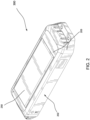
- a solar-powered asset tracker 300 is described with reference to FIG. 2 and FIG. 3 .
- FIG. 3 is a perspective view of a solar-powered asset tracker 300, in accordance with embodiments of the present disclosure.
- the solar-powered asset tracker 200 has a housing 202 for housing the internal components of the asset tracker 200.
- On the top surface 203 of the housing 202 there is a solar panel 250 acting as an energy harvester for the solar-powered asset tracker 300.
- the solar-powered asset tracker 300 When deployed, the solar-powered asset tracker 300 is coupled to an asset and located for optimal exposure to sunlight.
- a solar-powered asset tracker 300 is typically attached to a top surface of the asset so as to have exposure to direct sunlight.
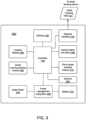
- FIG. 3 is a block diagram of a solar-powered asset tracker 300, in accordance with embodiments of the present disclosure.
- the solar-powered asset tracker 300 is an example of a solar-powered electronic device.
- the solar-powered asset tracker 300 includes a controller 230.
- a plurality of peripherals are coupled to the controller 230 by different types of interfaces.
- the peripherals include a memory 240, a network interface 220, an IMU 290, a short-range wireless communications module 270, sensors 204, a location module 206, and a serial communications module 280.
- the solar-powered asset tracker 300 also includes a solar panel 250 and a rechargeable battery 210.
- a power management subsystem 400 couples the solar panel 250 to the rechargeable battery 210, the controller 230, and the peripherals. Some of the peripherals shown may be optional as will be discussed below.
- the controller 230 may include one or any combination of a processor, a microprocessor, a microcontroller (MCU), a central processing unit (CPU), a System-on-Chip (SOC), a processing core, a state machine, a logic gate array, an application-specific integrated circuit (ASIC), a field-programmable gate array (FPGA), or any other hardware component or combination of hardware components capable of executing machine-executable programming instructions.
- the controller 230 may follow a Von Neumann Architecture, a Harvard Architecture, or a Modified Harvard Architecture.
- the controller 230 may be a Complex Instruction Set Computer (CISC) processor supporting a complex instruction set that can perform multiple operations in a single instruction.
- CISC Complex Instruction Set Computer
- the controller 230 may be a Reduced Instruction Set Computer (RISC) processor having a simplified and streamlined instruction set, and employs a pipeline architecture to optimize execution.
- the controller 230 may have a single processor core or multiple processor cores supporting parallel execution of instructions.
- the controller 230 may have an internal memory for storing machine-executable programming instructions to be executed by the controller 230 to carry out the steps of the methods described in this disclosure.
- RISC Reduced Instruction Set Computer
- the memory 240 is an electronic storage component that enables storage of data and machine-executable programming instructions.
- the memory 240 may be a read-only-memory (ROM) including a Programmable ROM (PROM), and Erasable Programmable ROM (EPROM), Electrically Erasable Programmable ROM (EEPROM), or Flash memory.
- ROM read-only-memory
- PROM Programmable ROM
- EPROM Erasable Programmable ROM
- EEPROM Electrically Erasable Programmable ROM
- Flash memory may be a random access memory (RAM) including Static RAM (SRAM) and Dynamic RAM (DRAM).
- the memory 240 may be a Ferroelectric RAM (FRAM), a Magnetic Random Access Memory (MRAM), or a Phase-Change Memory (PCM).
- FRAM Ferroelectric RAM
- MRAM Magnetic Random Access Memory
- PCM Phase-Change Memory
- the memory 240 may also be any combination of the aforementioned types.
- the memory 240 is for storing machine-executable programming instructions and/or data to support the functionality described in this disclosure.
- the memory 240 is coupled to the controller 230, via a memory bus, thus enabling the controller 230 to execute the machine-executable programming instructions stored in the memory 240 and to access the data stored therein.
- the location module 206 provides the location of the asset tracker 200.
- the location module 206 is a Global Navigation Satellite Systems (GNSS) transceiver using one or more of the above-mentioned GNSS technologies.
- the location module 206 determines the location of the solar-powered asset tracker 300 from a cellular network using cell tower triangulation.
- the location module 206 is coupled with the network interface 220, which in this case is a cellular modem, for receiving signal measurements from multiple nearby cell towers.
- the location module 206 uses the signal measurements to estimate the location of the solar-powered asset tracker 300.
- the location information determined by the location module 206 is sent to the controller 230.
- the location data may be in the form of a latitude and longitude or in Universal Transverse Mercator (UTM) coordinates.
- UDM Universal Transverse Mercator
- the sensors 204 may be one or more of: a temperature sensor, a pressure sensor, an optical sensor, a humidity sensor, a gas sensor, an acoustic sensor, a pH sensor, a soil moisture sensor, or any other suitable sensor indicating a condition pertaining to the asset 100 to which the solar-powered asset tracker 300 is coupled.
- the sensors 204 are coupled to the controller via any one of serial, parallel, or bus technologies. For example, some of the sensors 204 may connect to the controller 230 via a parallel interface.
- Other sensors 204 may connect to the controller 230 via a bus using any one of the known bus technologies such as the Industry Standard Architecture (ISA), Extended ISA (EISA), Micro Channel Architecture (MCA), Video Electronics Standards Association (VESA), Peripheral Component Interconnect (PCI), PCI Express (PCI-X), Personal Computer Memory Card Industry Association (PCMCIA), Accelerated Graphics Port (AGP), and Small Computer Systems Interface (SCSI).
- the sensors 204 may connect to the controller via a serial link such as a Universal Asynchronous Receiver Transmitter (UART), Serial Peripheral Interface (SPI), or Inter-Integrated Circuit (12C).
- UART Universal Asynchronous Receiver Transmitter
- SPI Serial Peripheral Interface
- the sensors 204 provide sensor data to the controller 230.
- Some asset trackers may not have any sensors 204 and may only provide location information and/or IMU information. Some asset trackers may have the capability of pairing with external sensors via a wired or a wireless interface.
- the IMU 290 is an inertial measurement unit.
- the IMU 290 is a device used to measure and provide information about the asset tracker's motion, orientation, and acceleration.
- the IMU 290 may be comprised of several components working together.
- the IMU 290 may be comprised of one or more accelerometer, a gyroscope, a magnetometer, and a barometer.
- An accelerometer measures linear acceleration in three axes (typically X, Y, and Z).
- a gyroscope measures the angular velocity or rate of rotation around each of the three axes.
- a magnetometer measures the strength and direction of a magnetic field and thus determines the heading or orientation relative to the Earth's magnetic field.
- a barometer measures the atmospheric pressure and that can be used to estimate changes in altitude.
- Some IMUs contain a microcontroller or a processor that runs sensor fusion algorithms to combine and process the data from the various above-mentioned sensors.
- Other IMUs contain a communication interface to interface with an external microcontroller or processor.
- Some asset trackers may not contain an IMU unit and may report motion determined from the change in location reported by the location module 206.
- the IMU 290 may communicate with the controller via a parallel interface, a serial interface using any one of the above-mentioned serial technologies, a bus interface using any one of the above-mentioned bus technologies, or may connect directly to General Purpose Input/Output (GPIO) and interrupt pins of the controller 230.
- GPIO General Purpose Input/Output
- the network interface 220 includes a cellular modem utilizing cellular technology.
- the network interface 220 uses the second-generation (2G) cellular technology which is based on the Global System for Mobiles (GSM) protocol and supports data transmission protocols such as the General Packet Radio Service (GPRS) or the Enhanced Data rates for GSM Evolution (EDGE).
- GSM Global System for Mobiles
- EDGE Enhanced Data rates for GSM Evolution
- the network interface 220 uses the Third-generation (3G) cellular technology utilizing the Universal Mobile Telephone System (UMTS) supporting data transfer using the High Speed Packet Access (HSPA) protocol.
- the network interface 220 uses the Fourth-generation cellular technology (4G) which uses the Long Term Evolution (LTE) protocol.
- 4G Fourth-generation cellular technology
- the network interface 220 uses the Fifth-generation (5G) cellular technology.
- the network interface 220 uses the Narrowband Internet of Things (NB-IoT) which is a low-power wide-area network (LPWAN) technology that is part of the Third Generation Partnership Project (3GPP) standard.
- NB-IoT Narrowband Internet of Things
- LPWAN low-power wide-area network
- the network interface 220 comprises a Wide Area Network (WAN) modem using non-cellular WAN technologies.
- the network interface 220 may use non-cellular WAN technologies.
- a non-cellular WAN technology that the network interface 220 can use is the Worldwide Interoperability For Microwave Access (WiMAX TM ) which is based on the IEEE 810.16 family of standards.
- WiMAX TM Worldwide Interoperability For Microwave Access
- Another example of a non-cellular WAN technology that the network interface 220 may use is Long Range Wide Area Network (LoRaWAN TM ) technology which is a low-power WAN protocol.
- LoRaWAN TM Long Range Wide Area Network
- Weightless is a family of open standard low-power WAN (LPWAN) technology that operate in the sub-GHz frequency bands.
- the network interface 220 uses a wired network technology when the solar-powered asset tracker 300 is coupled to an asset that provides wired network connectivity.
- wired network technologies include Ethernet, Fast Ethernet, Local Talk TM , Token Ring, Fiber Distributed Data Interface (FDDI), and Asynchronous Transfer Mode (ATM).
Landscapes
- Engineering & Computer Science (AREA)
- Power Engineering (AREA)
- Charge And Discharge Circuits For Batteries Or The Like (AREA)
Applications Claiming Priority (1)
| Application Number | Priority Date | Filing Date | Title |
|---|---|---|---|
| US202363540415P | 2023-09-26 | 2023-09-26 |
Publications (1)
| Publication Number | Publication Date |
|---|---|
| EP4531233A1 true EP4531233A1 (de) | 2025-04-02 |
Family
ID=90362955
Family Applications (1)
| Application Number | Title | Priority Date | Filing Date |
|---|---|---|---|
| EP24183716.0A Pending EP4531233A1 (de) | 2023-09-26 | 2024-06-21 | Verfahren und vorrichtung zur leistungsverwaltung in einer solarbetriebenen elektronischen vorrichtung |
Country Status (4)
| Country | Link |
|---|---|
| US (2) | US11973357B1 (de) |
| EP (1) | EP4531233A1 (de) |
| CN (1) | CN121970248A (de) |
| WO (1) | WO2025065078A1 (de) |
Families Citing this family (1)
| Publication number | Priority date | Publication date | Assignee | Title |
|---|---|---|---|---|
| US12306256B2 (en) * | 2022-07-07 | 2025-05-20 | Caterpillar Inc. | Sensor with self supplied negative rail for battery pack measurement |
Citations (9)
| Publication number | Priority date | Publication date | Assignee | Title |
|---|---|---|---|---|
| US5153497A (en) * | 1991-08-28 | 1992-10-06 | Eiden Glenn E | Circuit for regulating charging of a storage battery by a photovoltaic array |
| US5747967A (en) * | 1996-02-22 | 1998-05-05 | Midwest Research Institute | Apparatus and method for maximizing power delivered by a photovoltaic array |
| US20120256486A1 (en) * | 2011-04-06 | 2012-10-11 | Samsung Electronics Co., Ltd. | Electronic device using solar cell |
| WO2017211074A1 (zh) * | 2016-06-06 | 2017-12-14 | 西安华科光电有限公司 | 一种太阳能内红点瞄具 |
| CN108574333A (zh) * | 2018-08-01 | 2018-09-25 | 郑州源创智控有限公司 | 用于粮情检测分机的智能供电模块 |
| US20180337552A1 (en) * | 2017-05-22 | 2018-11-22 | Gary Osborne | Apparatus for a solar pathway light |
| US20190341800A1 (en) * | 2015-12-15 | 2019-11-07 | Mirai-Labo Kabushiki Kaisha | Charging device |
| US20200074397A1 (en) * | 2018-08-31 | 2020-03-05 | Calamp Corp. | Asset Tracker |
| US20220200325A1 (en) * | 2019-09-16 | 2022-06-23 | Weihai Xue | An apparatus, method and article for maximizing solar charge current through the use of split wire(s) in a solar array with solar panels connected in the combination of series and parallel |
Family Cites Families (20)
| Publication number | Priority date | Publication date | Assignee | Title |
|---|---|---|---|---|
| JPH0769750B2 (ja) * | 1989-09-08 | 1995-07-31 | 三菱電機株式会社 | 太陽電池電源系 |
| US6512466B2 (en) | 2000-05-17 | 2003-01-28 | Omega Patents, L.L.C. | Vehicle tracker with power saving features and related methods |
| US6819269B2 (en) | 2000-05-17 | 2004-11-16 | Omega Patents, L.L.C. | Vehicle tracker including battery monitoring feature and related methods |
| US6606561B2 (en) | 2000-05-17 | 2003-08-12 | Omega Patents, L.L.C. | Vehicle tracker including input/output features and related methods |
| CA2355426A1 (en) * | 2001-08-17 | 2003-02-17 | Luther Haave | A system and method for asset tracking |
| US20040196182A1 (en) * | 2003-04-03 | 2004-10-07 | Unnold Robert M. | Intelligent mobile asset management system |
| US20120235860A1 (en) | 2006-04-25 | 2012-09-20 | Ghazarian Ohanes D | Automatic GPS tracking system with passive or active battery circuitry |
| US20130009483A1 (en) * | 2011-05-31 | 2013-01-10 | Kawate Keith W | Power generator module connectivity control |
| US9787170B2 (en) * | 2012-02-13 | 2017-10-10 | Mitsubishi Electric Corporation | Power conversion device |
| US9609600B2 (en) | 2013-06-21 | 2017-03-28 | Micron Electronics LLC | Wireless communication system with enhanced power management |
| CN105990865A (zh) * | 2015-02-06 | 2016-10-05 | 中兴通讯股份有限公司 | 一种蓄电池装置及其充放电监控方法、装置及相应的系统 |
| US20220217517A1 (en) | 2015-03-20 | 2022-07-07 | PB, Inc | Battery beacon systems and methods of use |
| US10341483B2 (en) | 2016-08-08 | 2019-07-02 | Blackberry Limited | Method and mobile transceiver providing container security |
| US10103549B2 (en) * | 2016-11-10 | 2018-10-16 | Hamilton Sundstrand Corporation | Electric power system for a space vehicle |
| US10173547B1 (en) | 2016-12-02 | 2019-01-08 | Lytx, Inc. | Vehicle battery drainage avoidance |
| US10579123B2 (en) | 2018-01-12 | 2020-03-03 | Samsara Networks Inc. | Adaptive power management in a battery powered system based on expected solar energy levels |
| US11675042B1 (en) | 2020-03-18 | 2023-06-13 | Samsara Inc. | Systems and methods of remote object tracking |
| US11709500B2 (en) | 2020-04-14 | 2023-07-25 | Samsara Inc. | Gateway system with multiple modes of operation in a fleet management system |
| US12249859B2 (en) * | 2020-05-27 | 2025-03-11 | Qualcomm Incorporated | Adaptive power systems and techniques |
| EP3962124B1 (de) | 2020-08-24 | 2025-06-11 | Technology Trace Inc. | System und verfahren zum asset tracking |
-
2023
- 2023-11-14 US US18/508,646 patent/US11973357B1/en active Active
- 2023-11-14 US US18/508,628 patent/US11942815B1/en active Active
-
2024
- 2024-06-10 CN CN202480061527.7A patent/CN121970248A/zh active Pending
- 2024-06-10 WO PCT/CA2024/050778 patent/WO2025065078A1/en active Pending
- 2024-06-21 EP EP24183716.0A patent/EP4531233A1/de active Pending
Patent Citations (9)
| Publication number | Priority date | Publication date | Assignee | Title |
|---|---|---|---|---|
| US5153497A (en) * | 1991-08-28 | 1992-10-06 | Eiden Glenn E | Circuit for regulating charging of a storage battery by a photovoltaic array |
| US5747967A (en) * | 1996-02-22 | 1998-05-05 | Midwest Research Institute | Apparatus and method for maximizing power delivered by a photovoltaic array |
| US20120256486A1 (en) * | 2011-04-06 | 2012-10-11 | Samsung Electronics Co., Ltd. | Electronic device using solar cell |
| US20190341800A1 (en) * | 2015-12-15 | 2019-11-07 | Mirai-Labo Kabushiki Kaisha | Charging device |
| WO2017211074A1 (zh) * | 2016-06-06 | 2017-12-14 | 西安华科光电有限公司 | 一种太阳能内红点瞄具 |
| US20180337552A1 (en) * | 2017-05-22 | 2018-11-22 | Gary Osborne | Apparatus for a solar pathway light |
| CN108574333A (zh) * | 2018-08-01 | 2018-09-25 | 郑州源创智控有限公司 | 用于粮情检测分机的智能供电模块 |
| US20200074397A1 (en) * | 2018-08-31 | 2020-03-05 | Calamp Corp. | Asset Tracker |
| US20220200325A1 (en) * | 2019-09-16 | 2022-06-23 | Weihai Xue | An apparatus, method and article for maximizing solar charge current through the use of split wire(s) in a solar array with solar panels connected in the combination of series and parallel |
Also Published As
| Publication number | Publication date |
|---|---|
| US11942815B1 (en) | 2024-03-26 |
| US11973357B1 (en) | 2024-04-30 |
| WO2025065078A1 (en) | 2025-04-03 |
| CN121970248A (zh) | 2026-05-01 |
Similar Documents
| Publication | Publication Date | Title |
|---|---|---|
| US11487019B2 (en) | Power management in wireless tracking device operating with restricted power source | |
| US10123170B2 (en) | Energy storage management in solar-powered tracking devices | |
| US8258942B1 (en) | Lightweight portable tracking device | |
| CN103728644B (zh) | 一种定位系统及定位方法 | |
| JP2021536647A (ja) | アセットトラッカー | |
| US10107918B2 (en) | Solar-powered asset tracking device for energy-efficient GPS tracking | |
| US20110248846A1 (en) | Wireless Sensing Module and Method of Operation | |
| US11942815B1 (en) | Method and device for power management in a solar-powered electronic device | |
| CN113405602A (zh) | 杆塔状态监测装置 | |
| Krishna et al. | Cloud-based Monitoring of the Health of Battery using IoT | |
| CN214893429U (zh) | 杆塔状态监测装置 | |
| CN108132478A (zh) | 一种智能终端低功耗混合定位控制系统及方法 | |
| CN112020015A (zh) | 一种基于卫星物联网的物流卫星多模终端及低功耗方法 | |
| Balid | Fully autonomous self-powered intelligent wireless sensor for real-time traffic surveillance in smart cities | |
| KR20260070532A (ko) | 태양광 구동 전자 디바이스에서의 전력 관리 | |
| US20250126435A1 (en) | Commercial equipment location and status tracker | |
| Idris et al. | Smart Solar Safety Worker Helmet Using Accelerometer and GPS Sensor | |
| CN207148589U (zh) | 一种基于gnss的多传感器数据采集集成传输装置 | |
| CN107561988B (zh) | 一种环境监测方法 | |
| US20170350987A1 (en) | Low energy wi-fi device for location | |
| Kumberg et al. | Wake-up transceivers for structural health monitoring of bridges | |
| Teki et al. | Advancements in IoT-Based Battery Monitoring Systems for Electric Vehicles | |
| Handayani et al. | Alert, monitoring and tracking for electronic device prototype | |
| CN205864481U (zh) | 一种具有定位跟踪功能的摄像机电池 | |
| Perez et al. | Development of a cheap, GPS-based, radio-tracked, surface drifter for closed shallow-water bays |
Legal Events
| Date | Code | Title | Description |
|---|---|---|---|
| PUAI | Public reference made under article 153(3) epc to a published international application that has entered the european phase |
Free format text: ORIGINAL CODE: 0009012 |
|
| STAA | Information on the status of an ep patent application or granted ep patent |
Free format text: STATUS: THE APPLICATION HAS BEEN PUBLISHED |
|
| AK | Designated contracting states |
Kind code of ref document: A1 Designated state(s): AL AT BE BG CH CY CZ DE DK EE ES FI FR GB GR HR HU IE IS IT LI LT LU LV MC ME MK MT NL NO PL PT RO RS SE SI SK SM TR |
|
| STAA | Information on the status of an ep patent application or granted ep patent |
Free format text: STATUS: REQUEST FOR EXAMINATION WAS MADE |
|
| 17P | Request for examination filed |
Effective date: 20250912 |