EP4531258A1 - Circuit de conversion cc/ca et son procédé de commande, et procédé de modulation pour cycloconvertisseur - Google Patents
Circuit de conversion cc/ca et son procédé de commande, et procédé de modulation pour cycloconvertisseur Download PDFInfo
- Publication number
- EP4531258A1 EP4531258A1 EP22949034.7A EP22949034A EP4531258A1 EP 4531258 A1 EP4531258 A1 EP 4531258A1 EP 22949034 A EP22949034 A EP 22949034A EP 4531258 A1 EP4531258 A1 EP 4531258A1
- Authority
- EP
- European Patent Office
- Prior art keywords
- switching elements
- cycloconverter
- sets
- threshold range
- switching
- Prior art date
- Legal status (The legal status is an assumption and is not a legal conclusion. Google has not performed a legal analysis and makes no representation as to the accuracy of the status listed.)
- Pending
Links
Images





Classifications
-
- H—ELECTRICITY
- H02—GENERATION; CONVERSION OR DISTRIBUTION OF ELECTRIC POWER
- H02M—APPARATUS FOR CONVERSION BETWEEN AC AND AC, BETWEEN AC AND DC, OR BETWEEN DC AND DC, AND FOR USE WITH MAINS OR SIMILAR POWER SUPPLY SYSTEMS; CONVERSION OF DC OR AC INPUT POWER INTO SURGE OUTPUT POWER; CONTROL OR REGULATION THEREOF
- H02M1/00—Details of apparatus for conversion
- H02M1/0067—Converter structures employing plural converter units, other than for parallel operation of the units on a single load
- H02M1/007—Plural converter units in cascade
-
- H—ELECTRICITY
- H02—GENERATION; CONVERSION OR DISTRIBUTION OF ELECTRIC POWER
- H02M—APPARATUS FOR CONVERSION BETWEEN AC AND AC, BETWEEN AC AND DC, OR BETWEEN DC AND DC, AND FOR USE WITH MAINS OR SIMILAR POWER SUPPLY SYSTEMS; CONVERSION OF DC OR AC INPUT POWER INTO SURGE OUTPUT POWER; CONTROL OR REGULATION THEREOF
- H02M1/00—Details of apparatus for conversion
- H02M1/0067—Converter structures employing plural converter units, other than for parallel operation of the units on a single load
- H02M1/008—Plural converter units for generating at two or more independent and non-parallel outputs, e.g. systems with plural point of load switching regulators
-
- H—ELECTRICITY
- H02—GENERATION; CONVERSION OR DISTRIBUTION OF ELECTRIC POWER
- H02M—APPARATUS FOR CONVERSION BETWEEN AC AND AC, BETWEEN AC AND DC, OR BETWEEN DC AND DC, AND FOR USE WITH MAINS OR SIMILAR POWER SUPPLY SYSTEMS; CONVERSION OF DC OR AC INPUT POWER INTO SURGE OUTPUT POWER; CONTROL OR REGULATION THEREOF
- H02M1/00—Details of apparatus for conversion
- H02M1/08—Circuits specially adapted for the generation of control voltages for semiconductor devices incorporated in static converters
- H02M1/083—Circuits specially adapted for the generation of control voltages for semiconductor devices incorporated in static converters for the ignition at the zero crossing of the voltage or the current
-
- H—ELECTRICITY
- H02—GENERATION; CONVERSION OR DISTRIBUTION OF ELECTRIC POWER
- H02M—APPARATUS FOR CONVERSION BETWEEN AC AND AC, BETWEEN AC AND DC, OR BETWEEN DC AND DC, AND FOR USE WITH MAINS OR SIMILAR POWER SUPPLY SYSTEMS; CONVERSION OF DC OR AC INPUT POWER INTO SURGE OUTPUT POWER; CONTROL OR REGULATION THEREOF
- H02M1/00—Details of apparatus for conversion
- H02M1/08—Circuits specially adapted for the generation of control voltages for semiconductor devices incorporated in static converters
- H02M1/088—Circuits specially adapted for the generation of control voltages for semiconductor devices incorporated in static converters for the simultaneous control of series or parallel connected semiconductor devices
-
- H—ELECTRICITY
- H02—GENERATION; CONVERSION OR DISTRIBUTION OF ELECTRIC POWER
- H02M—APPARATUS FOR CONVERSION BETWEEN AC AND AC, BETWEEN AC AND DC, OR BETWEEN DC AND DC, AND FOR USE WITH MAINS OR SIMILAR POWER SUPPLY SYSTEMS; CONVERSION OF DC OR AC INPUT POWER INTO SURGE OUTPUT POWER; CONTROL OR REGULATION THEREOF
- H02M1/00—Details of apparatus for conversion
- H02M1/38—Means for preventing simultaneous conduction of switches
-
- H—ELECTRICITY
- H02—GENERATION; CONVERSION OR DISTRIBUTION OF ELECTRIC POWER
- H02M—APPARATUS FOR CONVERSION BETWEEN AC AND AC, BETWEEN AC AND DC, OR BETWEEN DC AND DC, AND FOR USE WITH MAINS OR SIMILAR POWER SUPPLY SYSTEMS; CONVERSION OF DC OR AC INPUT POWER INTO SURGE OUTPUT POWER; CONTROL OR REGULATION THEREOF
- H02M5/00—Conversion of AC power input into AC power output, e.g. for change of voltage, for change of frequency, for change of number of phases
- H02M5/02—Conversion of AC power input into AC power output, e.g. for change of voltage, for change of frequency, for change of number of phases without intermediate conversion into DC
- H02M5/04—Conversion of AC power input into AC power output, e.g. for change of voltage, for change of frequency, for change of number of phases without intermediate conversion into DC by static converters
- H02M5/22—Conversion of AC power input into AC power output, e.g. for change of voltage, for change of frequency, for change of number of phases without intermediate conversion into DC by static converters using discharge tubes with control electrode or semiconductor devices with control electrode
-
- H—ELECTRICITY
- H02—GENERATION; CONVERSION OR DISTRIBUTION OF ELECTRIC POWER
- H02M—APPARATUS FOR CONVERSION BETWEEN AC AND AC, BETWEEN AC AND DC, OR BETWEEN DC AND DC, AND FOR USE WITH MAINS OR SIMILAR POWER SUPPLY SYSTEMS; CONVERSION OF DC OR AC INPUT POWER INTO SURGE OUTPUT POWER; CONTROL OR REGULATION THEREOF
- H02M5/00—Conversion of AC power input into AC power output, e.g. for change of voltage, for change of frequency, for change of number of phases
- H02M5/02—Conversion of AC power input into AC power output, e.g. for change of voltage, for change of frequency, for change of number of phases without intermediate conversion into DC
- H02M5/04—Conversion of AC power input into AC power output, e.g. for change of voltage, for change of frequency, for change of number of phases without intermediate conversion into DC by static converters
- H02M5/22—Conversion of AC power input into AC power output, e.g. for change of voltage, for change of frequency, for change of number of phases without intermediate conversion into DC by static converters using discharge tubes with control electrode or semiconductor devices with control electrode
- H02M5/225—Conversion of AC power input into AC power output, e.g. for change of voltage, for change of frequency, for change of number of phases without intermediate conversion into DC by static converters using discharge tubes with control electrode or semiconductor devices with control electrode comprising two stages of AC-AC conversion, e.g. having a high frequency intermediate link
-
- H—ELECTRICITY
- H02—GENERATION; CONVERSION OR DISTRIBUTION OF ELECTRIC POWER
- H02M—APPARATUS FOR CONVERSION BETWEEN AC AND AC, BETWEEN AC AND DC, OR BETWEEN DC AND DC, AND FOR USE WITH MAINS OR SIMILAR POWER SUPPLY SYSTEMS; CONVERSION OF DC OR AC INPUT POWER INTO SURGE OUTPUT POWER; CONTROL OR REGULATION THEREOF
- H02M5/00—Conversion of AC power input into AC power output, e.g. for change of voltage, for change of frequency, for change of number of phases
- H02M5/02—Conversion of AC power input into AC power output, e.g. for change of voltage, for change of frequency, for change of number of phases without intermediate conversion into DC
- H02M5/04—Conversion of AC power input into AC power output, e.g. for change of voltage, for change of frequency, for change of number of phases without intermediate conversion into DC by static converters
- H02M5/22—Conversion of AC power input into AC power output, e.g. for change of voltage, for change of frequency, for change of number of phases without intermediate conversion into DC by static converters using discharge tubes with control electrode or semiconductor devices with control electrode
- H02M5/275—Conversion of AC power input into AC power output, e.g. for change of voltage, for change of frequency, for change of number of phases without intermediate conversion into DC by static converters using discharge tubes with control electrode or semiconductor devices with control electrode using devices of a triode or transistor type requiring continuous application of a control signal
- H02M5/293—Conversion of AC power input into AC power output, e.g. for change of voltage, for change of frequency, for change of number of phases without intermediate conversion into DC by static converters using discharge tubes with control electrode or semiconductor devices with control electrode using devices of a triode or transistor type requiring continuous application of a control signal using semiconductor devices only
- H02M5/2932—Conversion of AC power input into AC power output, e.g. for change of voltage, for change of frequency, for change of number of phases without intermediate conversion into DC by static converters using discharge tubes with control electrode or semiconductor devices with control electrode using devices of a triode or transistor type requiring continuous application of a control signal using semiconductor devices only with automatic control of output voltage, current or power
- H02M5/2937—Conversion of AC power input into AC power output, e.g. for change of voltage, for change of frequency, for change of number of phases without intermediate conversion into DC by static converters using discharge tubes with control electrode or semiconductor devices with control electrode using devices of a triode or transistor type requiring continuous application of a control signal using semiconductor devices only with automatic control of output voltage, current or power using whole cycle control, i.e. switching an integer number of whole or half cycles of the AC input voltage
-
- H—ELECTRICITY
- H02—GENERATION; CONVERSION OR DISTRIBUTION OF ELECTRIC POWER
- H02M—APPARATUS FOR CONVERSION BETWEEN AC AND AC, BETWEEN AC AND DC, OR BETWEEN DC AND DC, AND FOR USE WITH MAINS OR SIMILAR POWER SUPPLY SYSTEMS; CONVERSION OF DC OR AC INPUT POWER INTO SURGE OUTPUT POWER; CONTROL OR REGULATION THEREOF
- H02M7/00—Conversion of AC power input into DC power output; Conversion of DC power input into AC power output
- H02M7/42—Conversion of DC power input into AC power output without possibility of reversal
-
- H—ELECTRICITY
- H02—GENERATION; CONVERSION OR DISTRIBUTION OF ELECTRIC POWER
- H02M—APPARATUS FOR CONVERSION BETWEEN AC AND AC, BETWEEN AC AND DC, OR BETWEEN DC AND DC, AND FOR USE WITH MAINS OR SIMILAR POWER SUPPLY SYSTEMS; CONVERSION OF DC OR AC INPUT POWER INTO SURGE OUTPUT POWER; CONTROL OR REGULATION THEREOF
- H02M7/00—Conversion of AC power input into DC power output; Conversion of DC power input into AC power output
- H02M7/42—Conversion of DC power input into AC power output without possibility of reversal
- H02M7/44—Conversion of DC power input into AC power output without possibility of reversal by static converters
- H02M7/48—Conversion of DC power input into AC power output without possibility of reversal by static converters using discharge tubes with control electrode or semiconductor devices with control electrode
- H02M7/4807—Conversion of DC power input into AC power output without possibility of reversal by static converters using discharge tubes with control electrode or semiconductor devices with control electrode having a high frequency intermediate AC stage
-
- H—ELECTRICITY
- H02—GENERATION; CONVERSION OR DISTRIBUTION OF ELECTRIC POWER
- H02M—APPARATUS FOR CONVERSION BETWEEN AC AND AC, BETWEEN AC AND DC, OR BETWEEN DC AND DC, AND FOR USE WITH MAINS OR SIMILAR POWER SUPPLY SYSTEMS; CONVERSION OF DC OR AC INPUT POWER INTO SURGE OUTPUT POWER; CONTROL OR REGULATION THEREOF
- H02M7/00—Conversion of AC power input into DC power output; Conversion of DC power input into AC power output
- H02M7/42—Conversion of DC power input into AC power output without possibility of reversal
- H02M7/44—Conversion of DC power input into AC power output without possibility of reversal by static converters
- H02M7/48—Conversion of DC power input into AC power output without possibility of reversal by static converters using discharge tubes with control electrode or semiconductor devices with control electrode
- H02M7/4815—Resonant converters
-
- H—ELECTRICITY
- H02—GENERATION; CONVERSION OR DISTRIBUTION OF ELECTRIC POWER
- H02M—APPARATUS FOR CONVERSION BETWEEN AC AND AC, BETWEEN AC AND DC, OR BETWEEN DC AND DC, AND FOR USE WITH MAINS OR SIMILAR POWER SUPPLY SYSTEMS; CONVERSION OF DC OR AC INPUT POWER INTO SURGE OUTPUT POWER; CONTROL OR REGULATION THEREOF
- H02M7/00—Conversion of AC power input into DC power output; Conversion of DC power input into AC power output
- H02M7/42—Conversion of DC power input into AC power output without possibility of reversal
- H02M7/44—Conversion of DC power input into AC power output without possibility of reversal by static converters
- H02M7/48—Conversion of DC power input into AC power output without possibility of reversal by static converters using discharge tubes with control electrode or semiconductor devices with control electrode
- H02M7/53—Conversion of DC power input into AC power output without possibility of reversal by static converters using discharge tubes with control electrode or semiconductor devices with control electrode using devices of a triode or transistor type requiring continuous application of a control signal
- H02M7/537—Conversion of DC power input into AC power output without possibility of reversal by static converters using discharge tubes with control electrode or semiconductor devices with control electrode using devices of a triode or transistor type requiring continuous application of a control signal using semiconductor devices only, e.g. single switched pulse inverters
- H02M7/5387—Conversion of DC power input into AC power output without possibility of reversal by static converters using discharge tubes with control electrode or semiconductor devices with control electrode using devices of a triode or transistor type requiring continuous application of a control signal using semiconductor devices only, e.g. single switched pulse inverters in a bridge configuration
- H02M7/53871—Conversion of DC power input into AC power output without possibility of reversal by static converters using discharge tubes with control electrode or semiconductor devices with control electrode using devices of a triode or transistor type requiring continuous application of a control signal using semiconductor devices only, e.g. single switched pulse inverters in a bridge configuration with automatic control of output voltage or current
-
- H—ELECTRICITY
- H02—GENERATION; CONVERSION OR DISTRIBUTION OF ELECTRIC POWER
- H02M—APPARATUS FOR CONVERSION BETWEEN AC AND AC, BETWEEN AC AND DC, OR BETWEEN DC AND DC, AND FOR USE WITH MAINS OR SIMILAR POWER SUPPLY SYSTEMS; CONVERSION OF DC OR AC INPUT POWER INTO SURGE OUTPUT POWER; CONTROL OR REGULATION THEREOF
- H02M7/00—Conversion of AC power input into DC power output; Conversion of DC power input into AC power output
- H02M7/42—Conversion of DC power input into AC power output without possibility of reversal
- H02M7/44—Conversion of DC power input into AC power output without possibility of reversal by static converters
- H02M7/48—Conversion of DC power input into AC power output without possibility of reversal by static converters using discharge tubes with control electrode or semiconductor devices with control electrode
- H02M7/53—Conversion of DC power input into AC power output without possibility of reversal by static converters using discharge tubes with control electrode or semiconductor devices with control electrode using devices of a triode or transistor type requiring continuous application of a control signal
- H02M7/537—Conversion of DC power input into AC power output without possibility of reversal by static converters using discharge tubes with control electrode or semiconductor devices with control electrode using devices of a triode or transistor type requiring continuous application of a control signal using semiconductor devices only, e.g. single switched pulse inverters
- H02M7/5387—Conversion of DC power input into AC power output without possibility of reversal by static converters using discharge tubes with control electrode or semiconductor devices with control electrode using devices of a triode or transistor type requiring continuous application of a control signal using semiconductor devices only, e.g. single switched pulse inverters in a bridge configuration
- H02M7/53871—Conversion of DC power input into AC power output without possibility of reversal by static converters using discharge tubes with control electrode or semiconductor devices with control electrode using devices of a triode or transistor type requiring continuous application of a control signal using semiconductor devices only, e.g. single switched pulse inverters in a bridge configuration with automatic control of output voltage or current
- H02M7/53873—Conversion of DC power input into AC power output without possibility of reversal by static converters using discharge tubes with control electrode or semiconductor devices with control electrode using devices of a triode or transistor type requiring continuous application of a control signal using semiconductor devices only, e.g. single switched pulse inverters in a bridge configuration with automatic control of output voltage or current with digital control
-
- H—ELECTRICITY
- H02—GENERATION; CONVERSION OR DISTRIBUTION OF ELECTRIC POWER
- H02M—APPARATUS FOR CONVERSION BETWEEN AC AND AC, BETWEEN AC AND DC, OR BETWEEN DC AND DC, AND FOR USE WITH MAINS OR SIMILAR POWER SUPPLY SYSTEMS; CONVERSION OF DC OR AC INPUT POWER INTO SURGE OUTPUT POWER; CONTROL OR REGULATION THEREOF
- H02M1/00—Details of apparatus for conversion
- H02M1/0048—Circuits or arrangements for reducing losses
- H02M1/0054—Transistor switching losses
- H02M1/0058—Transistor switching losses by employing soft switching techniques, i.e. commutation of transistors when applied voltage is zero or when current flow is zero
-
- H—ELECTRICITY
- H02—GENERATION; CONVERSION OR DISTRIBUTION OF ELECTRIC POWER
- H02M—APPARATUS FOR CONVERSION BETWEEN AC AND AC, BETWEEN AC AND DC, OR BETWEEN DC AND DC, AND FOR USE WITH MAINS OR SIMILAR POWER SUPPLY SYSTEMS; CONVERSION OF DC OR AC INPUT POWER INTO SURGE OUTPUT POWER; CONTROL OR REGULATION THEREOF
- H02M1/00—Details of apparatus for conversion
- H02M1/0095—Hybrid converter topologies, e.g. NPC mixed with flying capacitor, thyristor converter mixed with MMC or charge pump mixed with buck
-
- Y—GENERAL TAGGING OF NEW TECHNOLOGICAL DEVELOPMENTS; GENERAL TAGGING OF CROSS-SECTIONAL TECHNOLOGIES SPANNING OVER SEVERAL SECTIONS OF THE IPC; TECHNICAL SUBJECTS COVERED BY FORMER USPC CROSS-REFERENCE ART COLLECTIONS [XRACs] AND DIGESTS
- Y02—TECHNOLOGIES OR APPLICATIONS FOR MITIGATION OR ADAPTATION AGAINST CLIMATE CHANGE
- Y02E—REDUCTION OF GREENHOUSE GAS [GHG] EMISSIONS, RELATED TO ENERGY GENERATION, TRANSMISSION OR DISTRIBUTION
- Y02E10/00—Energy generation through renewable energy sources
- Y02E10/50—Photovoltaic [PV] energy
- Y02E10/56—Power conversion systems, e.g. maximum power point trackers
Definitions
- the present invention generally relates to the field of inverters, and in particular, to a DC/AC conversion circuit and a control method therefor, and a modulation method for a cycloconverter.
- a DC (direct current) /AC (alternating current) conversion circuit is widely applied in grid-connected power conversion applications, such as renewable energy power generation, energy storage system, and electric vehicle charging.
- a DC voltage is low
- a two-stage conversion circuit is usually required to implement an inverter function.
- a former DC/DC conversion circuit is applied to boost the low DC voltage to a high DC voltage, then the high DC voltage is provided to a latter bridge DC/AC inverter circuit for inversion.
- An isolated DC/AC conversion circuit based on a cycloconverter can reduce the number of circuit stages, and the power conversion from the low DC voltage to an AC voltage can be achieved with one-stage circuit, thereby reducing circuit complexity.
- a controller cannot obtain an accurate time of the zero crossing of the grid voltage, and a polarity change of the grid voltage may cause a short-circuit risk in a bridge arm of the cycloconverter.
- a DC/AC conversion circuit and a control method therefor, and a modulation method for a cycloconverter are provided.
- a DC/AC conversion circuit including an inverter unit, at least one cycloconverter, and a controller.
- the inverter unit is configured for converting a direct current into an alternating current.
- the at least one cycloconverter is connected to the inverter unit, the cycloconverter includes a plurality of sets of switching elements, the plurality of sets of switching elements are connected to an output port of the inverter unit respectively and configured for performing AC-to-AC conversion, and an output port of the cycloconverter is configured to connect to a power grid and provide an alternating current output.
- Each of the plurality of sets of switching elements includes at least two switching elements which are connected in reverse.
- the controller is connected to the inverter unit and the cycloconverter and is configured for controlling, when a grid voltage is within a threshold range, corresponding two of the plurality of sets of switching elements to complementarily turn on.
- the threshold range includes a zero crossing.
- the controller when the grid voltage is within the threshold range, the controller is configured for controlling the corresponding two of the plurality of sets of switching elements to turn on or off at a high switching frequency.
- the controller when the grid voltage is within the threshold range, the controller is configured for controlling switching elements in each of the corresponding two of the plurality of sets of switching elements to turn on or off simultaneously.
- a dead time is set between any two sets of switching elements.
- the controller includes a hysteresis comparison unit, the hysteresis comparison unit is configured to compare the grid voltage with a first threshold and a second threshold respectively and control an operating state of the cycloconverter according to a comparison result.
- the first threshold and the second threshold are determined based on the threshold range.
- a set of switching elements of the cycloconverter includes a first switching element and a second switching element
- another set of switching elements of the cycloconverter includes a third switching element and a fourth switching element
- the first switching element, the second switching element, the third switching element, and the fourth switching element are connected in series between two output terminals of the cycloconverter.
- the cycloconverter includes three sets of switching elements which are configured to provide a three-phase alternating current output, a first set of switching elements includes a first switching element and a second switching element, a second set of switching elements includes a third switching element and a fourth switching element, a third set of switching elements includes a fifth switching element and a sixth switching element, and any two of the three sets of switching elements are connected in series between corresponding two output terminals of the cycloconverter.
- each of the plurality of sets of switching elements includes a first switching element and a second switching element, when the grid voltage is in a positive half-cycle or a negative half-cycle and is not in the threshold range, one of the first switching element and the second switching element is controlled to be in an always-on state, and the other one of the first switching element and the second switching element is controlled to turn on or off at a high switching frequency.
- the circuit further includes a transformer, the inverter unit is connected to a primary side of the transformer, and the cycloconverter is connected to a secondary side of the transformer.
- the circuit further includes at least one resonant unit connected in series to the secondary side of the transformer, and an output terminal of the resonant unit is connected to a corresponding cycloconverter.
- the circuit further includes a filter unit.
- the filter unit is connected to an output port of the cycloconverter, and configured to filter the alternating current output of the cycloconverter.
- a modulation method for a cycloconverter includes a plurality of sets of switching elements, each of the plurality of sets of switching elements includes at least two switching elements which are connected in reverse, an output port of the cycloconverter is configured to connect to a power grid and provide an alternating current output, and the method includes: when a grid voltage is within a threshold range, controlling corresponding two of the plurality of sets of switching elements to complementarily turn on.
- the threshold range includes a zero crossing.
- the method further includes: when the grid voltage is within the threshold range, controlling the corresponding two of the plurality of sets of switching elements to turn on or off at a high switching frequency.
- the method further includes: when the grid voltage is within the threshold range, controlling switching elements in each of the corresponding two of the plurality of sets of switching elements to turn on or off simultaneously.
- a control method of a DC/AC conversion circuit is further provided and configured to control the DC/AC conversion circuit in the first aspect.
- the method includes: when the grid voltage is within the threshold range, controlling the corresponding two of the plurality of sets of switching elements to complementarily turn on.
- the threshold range includes the zero crossing.
- the method further includes: when the grid voltage is within the threshold range, controlling the corresponding two of the plurality of sets of switching elements to turn on or off at a high switching frequency.
- the method further includes: when the grid voltage is within the threshold range, controlling switching elements in each of the corresponding two of the plurality of sets of switching elements to turn on or off simultaneously.
- Words such as "join”, “connect”, “couple”, and the like involved in the present invention are not limited to physical or mechanical connections, and may include electrical connections, whether direct or indirect.
- "A plurality of” involved in the present invention means two or more.
- the term “and/or” describes an association relationship between associated objects and represents that three relationships may exist. For example, A and/or B may represent the following three cases: only A exists, both A and B exist, and only B exists.
- the terms “first”, “second”, “third”, and the like involved in the present invention are only intended to distinguish similar objects and do not represent specific ordering of the objects.
- FIG. 1 is a first schematic diagram of a DC/AC conversion circuit in an embodiment of the present invention.
- the DC/AC conversion circuit includes an inverter unit 101, at least one cycloconverter 102, and a controller 103.
- the inverter unit 101 is configured for converting a direct current into an alternating current.
- the at least one cycloconverter 102 is connected to the inverter unit 101, the cycloconverter 102 includes a plurality of sets of switching elements, the plurality of sets of switching elements are connected to an output port of the inverter unit 101 respectively and configured for performing AC-to-AC conversion, and an output port of the at least one cycloconverter 102 is configured to connect to a power grid and provide an alternating current output.
- Each of the plurality of sets of switching elements includes at least two switching elements which are connected in reverse.
- the controller 103 is connected to the inverter unit 101 and the at least one cycloconverter 102 and is configured for controlling, when a grid voltage is within a threshold range, corresponding two of the plurality of sets of switching elements to complementarily turn on.
- the threshold range includes a zero crossing.
- the at least one cycloconverter 102 is configured to convert a highfrequency alternating current into a power-frequency alternating current.
- the quantity of the at least one cycloconverter 102 may be set according to a practical requirement.
- the quantity of sets of switching elements of the cycloconverter 102 may be determined by the quantity of phases of the alternating current output. In an embodiment, when a three-phase alternating current output needs to be provided, the cycloconverter 102 may need three sets of switching elements.
- the two sets of switching elements may be controlled to complementarily turn on.
- the two sets of switching elements corresponding to the phase voltage may be controlled to complementarily turn on.
- the controller 103 may control the corresponding two of the plurality of sets of switching elements to complementarily turn on.
- the threshold range includes the zero crossing, so that the short circuit is not caused in the cycloconverter.
- the threshold range may be set according to a practical requirement. Specifically, the threshold range may be a range between a positive threshold and a negative threshold which are near the zero crossing. Generally, absolute values of the positive threshold and the negative threshold may be same.
- the grid voltage may frequently cross zero for many times near the zero crossing.
- the drive logic of the switching elements in the positive half-cycle and the negative half-cycle of the grid voltage may be different, so that the drive logic may jump between the drive logic of the positive half-cycle and the drive logic of the negative half-cycle quickly and frequently, thus easily introducing interference to a system, and causing distortion of a power or a grid-connected current waveform at the zero crossing.
- the drive logic of synchronous switching may be applied, i.e., when the grid voltage is within the threshold range, the controller 103 controls the corresponding two of the plurality of sets of switching elements to complementarily turn on, and no frequent jumping between the drive logic of the positive half-cycle and the drive logic of the negative half-cycle may exist, thereby solving the foregoing technical problem.
- the controller 103 is configured for controlling the corresponding two of the plurality of sets of switching elements to turn on or off at a high switching frequency.
- the high switching frequency may be any frequency greater than a frequency of the grid voltage.
- the controller 103 is configured for controlling switching elements in each of the corresponding two of the plurality of sets of switching elements to turn on or off simultaneously, to avoid the short circuit between the output terminals of the cycloconverter.
- a dead time may be set between any two sets of switching elements of the cycloconverter, to prevent a bridge between the output terminals of the cycloconverter from shoot through.
- the dead time may be set according to a practical requirement.
- the controller 103 may include a hysteresis comparison unit, the hysteresis comparison unit is configured to compare the grid voltage with a first threshold and a second threshold respectively and control an operating state of the at least one cycloconverter according to a comparison result.
- the first threshold and the second threshold may be determined based on the threshold range.
- the threshold range is [-vth, +vth]
- the first threshold is opposite to and the second threshold
- the first threshold may be -vth
- the second threshold may be +vth
- the first threshold and the second threshold may be two thresholds near -vth and +vth, respectively.
- the inverter unit 101 may be a current-type inverter circuit or a voltage-type inverter circuit.
- the DC/AC conversion circuit may further include a filter unit 104.
- the filter unit 104 may be connected to an output port of the cycloconverter 102 and configured to filter the alternating current output of the cycloconverter 102.
- the DC/AC conversion circuit may further include a transformer 105.
- the transformer 105 is configured for boosting and electrical isolation.
- the inverter unit 101 may be connected to a primary side of the transformer 105, and the cycloconverter 102 may be connected to a secondary side of the transformer 105.
- the quantity of secondary windings of the transformer 105 is same as that of the cycloconverters 102.
- the DC/AC conversion circuit may further include at least one resonant unit 106.
- An output terminal of the resonant unit may be connected to a corresponding cycloconverter.
- the resonant unit 106 is configured for the soft switching of the switching elements in the DC/AC conversion circuit, thereby reducing circuit losses.
- the resonant unit 106 may be connected between the primary side of the transformer 105 and the inverter unit 101, and the circuit form of the resonant unit 106 may be a single L (Inductor), an LC (Inductor-Capacitor), a CLLC (Capacitor-Inductor-Inductor-Capacitor), or the like.
- the controller 103 may implement AC-to-AC conversion by controlling a duty cycle and a phase difference of on signals of the switching elements in the plurality of sets of switching elements.
- the controller 103 may control an operating state of a corresponding switching element by corresponding drive logic, to control a corresponding cycloconverter 102 to keep a freewheeling state, thereby effectively reducing a voltage stress of the switching element.
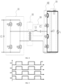
- the inverter unit 101 of the DC/AC conversion circuit may use an H-bridge, and an input port of the inverter unit 101 may be connected to a capacitor C1 in parallel.
- the inverter unit 101 may include a switch Q1H, a switch Q1L, a switch Q2H, and a switch Q2L.
- a cycloconverter 102 may include two sets of switching elements, the two sets of switching elements are connected in series, and the switching elements in each set of switching elements are connected in a common source connection manner. Specifically, the two sets of switching elements may be connected in series between two output terminals of the cycloconverter 102 to form a bridge arm.
- a first set of switching elements of the cycloconverter 102 may include a switch Q3 and a switch Q4 having a common source connection
- a second set of switching elements of the cycloconverter 102 may include a switch Q5 and a switch Q6 having a common source connection
- the two sets of switching elements may be commonly connected to a middle point of the bridge arm
- the output port of the cycloconverter 102 may be connected to an alternating current grid Vg via the filter unit 104
- the filter unit 104 may include a capacitor C3 connected to the output port of the cycloconverter 102 in parallel and an inductor L2 connected to a first output terminal of the cycloconverter 102.
- a second output terminal of the cycloconverter 102 may be connected to a terminal of a secondary winding of the transformer 105, and the other terminal of the secondary winding of the transformer 105 may be connected to the middle point of the bridge arm of the cycloconverter 102 via a resonant unit 106.
- the resonant unit 106 may include an inductor L1 and a capacitor C2 which are connected in series.
- drive signals of the switching elements of the cycloconverter 102 when the grid voltage is in the positive half-cycle may refer to FIG. 6
- drive signals of the switching elements of the cycloconverter 102 when the grid voltage is in the negative half-cycle may refer to FIG. 7 .
- the switch Q1H and the switch Q1L of the inverter unit 101 may operate complementarily with a duty cycle of 50%
- the switch Q2H and the switch Q2L of the inverter unit 101 may operate complementarily with a duty cycle of 50%
- an output voltage of the inverter unit 101 may be controlled by controlling a phase shift between two half bridges.
- the cycloconverter 102 may apply the drive logic of the positive half-cycle, i.e., the switch Q4 and the switch Q6 may keep an always-on state, the switch Q3 and the switch Q5 may operate complementarily with the duty cycle of 50%, for example, and the dead time of driving signals may be, for example, Td.
- the cycloconverter 102 may apply the drive logic of the negative half-cycle, i.e., the switch Q3 and the switch Q5 may in the always-on state, the switch Q4 and the switch Q6 may operate complementarily with the duty cycle of 50%, for example.
- the inverter unit 101 may be controlled to implement inversion and the cycloconverter 102 may be controlled to implement AC-to-AC conversion by the foregoing drive logic, and the power conversion from direct current to alternating current is achieved finally.
- the bridge arm of the cycloconverter 102 operates under the drive logic of positive half-cycle, the grid voltage vg is changed suddenly to be negative voltage, and the drive logic may not be switched in time, causing shoot through in the bridge arm between the output terminals of the cycloconverter 102.
- the controller 103 may control the switch Q3 and the switch Q4 to turn on or off synchronously, and control the switch Q5 and the switch Q6 to turn on or off synchronously, and the two sets of switches may be turned on complementarily, referring to FIG. 9 .
- an operating status of the cycloconverter 102 may refer to FIG. 10 .
- output voltages of the cycloconverter 102 may be the grid voltage vg and 0 respectively, which is consistent with a normal output voltage in the positive half-cycle or in the negative half-cycle of the power grid. Since there is always one set of switches having a common source connection that is in an off state, positive and negative voltages may be blocked, thereby avoiding the shoot through in the bridge arm between the output terminals. Therefore, there is no short-circuit path between the output terminals of the cycloconverter 102.
- the corresponding two of the plurality of sets of switching elements may be controlled to be turned on complementarily. Therefore, there is no case that two sets of switching elements between the two output terminals are tuned on at the same time at any moment, thereby effectively avoiding a short-circuit risk in the bridge arm between the output terminals of the cycloconverter caused by a voltage distortion near the zero crossing of the grid voltage, and improving reliability of the DC/AC conversion circuit.
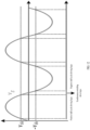
- FIG. 12 shows a schematic timing diagram of drive logic of the cycloconverter in an embodiment of the present invention.
- the drive logic of the positive half-cycle may be applied
- the drive logic of the negative half-cycle may be applied
- the drive logic of synchronous switching may be applied, so as to achieve the driving of the switch throughout a cycle of the grid voltage.
- the cycloconverter 102 may include at least two bridge arms, and each bridge arm is formed by two sets of switching elements connected in series between the output terminals of the cycloconverter 102, the at least two bridge arms may be connected in parallel, a terminal of a secondary winding of a transformer 105 may be connected to a middle point of a bridge arm via a resonant unit 106, and the other terminal of the secondary winding of the transformer 105 may be connected to a middle point of another bridge arm.
- the grid voltage is between the two thresholds, i.e., within the threshold range, the two sets of switching elements in the same bridge arm may be turned on complementarily.
- the drive logic of synchronous switching may be applied, i.e., switching elements of each of the two sets of switching elements may be controlled to turn on or off simultaneously, and turn on or off at the high switching frequency.
- switching elements of each of the two sets of switching elements may be controlled to be in the always-on state, and the other switching element of the same set of switching elements may be controlled to turn on or off at the high switching frequency.
- an input port of the inverter unit 101 of the DC/AC conversion circuit may be connected to a capacitor C4 in parallel, and the inverter unit 101 may include a switch Q7H, a switch Q7L, a switch Q8H, and a switch Q8L.
- a terminal of a secondary winding of a transformer 105 may be connected to a cycloconverter 102 via a resonant unit 106, and the resonant unit 106 may include an inductor L3 and a capacitor C5 connected in series.
- a first set of switching elements of the cycloconverter 102 may include a switch Q9 and a switch Q10 having a common source connection
- a second set of switching elements of the cycloconverter 102 may include a switch Q11 and a switch Q12 having a common source connection.
- the two sets of the switch elements may be connected to a middle point of a bridge arm, respectively.
- a terminal of a secondary winding of a transformer 105 may be connected to a middle point between the switch Q9 and the switch Q10 via a resonant unit 106, and the other terminal of the secondary winding of the transformer 105 may be connected to a middle point between the switch Q11 and the switch Q12.
- the output port of the cycloconverter 102 may be connected to the alternating current grid Vg via a filter unit 104, and the filter unit 104 may include a capacitor C6 connected to the output port of the cycloconverter 102 in parallel and an inductor L4 connected to a first output terminal of the cycloconverter 102.
- the cycloconverter 102 may apply the drive logic of the positive half-cycle, i.e., the switch Q10 and the switch Q12 may be in the always-on state, the switch Q9 and the switch Q11 may operate complementarily with a duty cycle of 50%, and the dead time may be, for example, Td.
- the cycloconverter 102 may apply the drive logic of the negative half-cycle, i.e., the switch Q9 and the switch Q11 may be in the always-on state, the switch Q11 and the switch Q12 may operate complementarily with a duty cycle of 50%.
- the drive logic of synchronous switching may be applied.
- the controller 103 may control the switch Q9 and the switch Q10 to turn on or off synchronously, and control the switch Q11 and the switch Q12 to turn on or off synchronously, and the two sets of switches may be turned on complementarily.
- an input port of the inverter unit 101 of the DC/AC conversion circuit may be connected to a capacitor C7 in parallel, and the inverter unit 101 may include a switch Q13H, a switch Q14L, a switch Q15H, and a switch Q16L.
- a terminal of a secondary winding of a transformer 105 may be connected to a cycloconverter 102 via a resonant unit 106, and the resonant unit 106 may include an inductor L5 and a capacitor C8 connected in series.
- a first set of switching elements of the cycloconverter 102 may include a switch Q18 and a switch Q19 having a common source connection
- a second set of the cycloconverter 102 may include a switch Q17 and a switch Q20 that are connected in anti-series via the first set of switching elements.
- a drain of the switch Q18 may be connected to a source of the switch Q17
- a drain of the switch Q19 may be connected to a source of the switch Q20.
- the output port of the cycloconverter 102 may be connected to the alternating current grid Vg via a filter unit 104, and the filter unit 104 may include a capacitor C9 connected to the output port of the cycloconverter 102 in parallel and an inductor L6 connected to a first output terminal of the cycloconverter 102.
- the cycloconverter 102 may apply the drive logic of the positive half-cycle, i.e., the switch Q19 and the switch Q20 may be in the always-on state, the switch Q17 and the switch Q18 may operate complementarily with a duty cycle of 50%, and the dead time may be, for example, Td.
- the cycloconverter 102 may apply the drive logic of the negative half-cycle, i.e., the switch Q17 and the switch Q18 may be in the always-on state, the switch Q19 and the switch Q20 may operate complementarily with a duty cycle of 50%.
- the drive logic of synchronous switching may be applied.
- the controller 103 may control the switch Q17 and the switch Q20 to turn on or off synchronously, and control the switch Q18 and the switch Q19 to turn on or off synchronously, and the two sets of switches may be turned on complementarily.
- an input port of the inverter unit 101 of the DC/AC conversion circuit may be connected to a capacitor C14 in parallel, and the inverter unit 101 may include a switch Q29H, a switch Q29L, a switch Q30H, and a switch Q30L.
- a cycloconverter 102 may include two sets of switching elements. In each of the two sets of switching elements, the switching elements may be connected in anti-series. Each of the two sets of switching elements may be connected in series with a capacitor. Specifically, the two sets of switching elements may be connected between the two output terminals of the cycloconverter 102 in series to form a bridge arm.
- a first set of switching elements may include a switch Q31 and a switch Q32 having a common source connection
- a second set of switching elements may include a switch Q33 and a switch Q34 having a common source connection.
- the first set of switching elements and a capacitor C15 may be connected to a node, and the node may be served as a first output terminal of the cycloconverter 102.
- the second set of switching elements and a capacitor C16 may be connected to another node, and the another node may be served as a second output terminal of the cycloconverter 102.
- a terminal of a secondary winding of the transformer 105 may be connected to a middle point of a bridge arm of the cycloconverter 102 via an inductor L8.
- a resonant unit 106 may be defined by the inductor L8, the capacitor C15, and the capacitor C16.
- the output port of the cycloconverter 102 may be connected to the alternating current grid Vg via a filter unit 104, and the filter unit 104 may include a capacitor C17 connected to the output port of the cycloconverter 102 in parallel and an inductor L9 connected to a first output terminal of the cycloconverter 102.
- the cycloconverter 102 may apply the drive logic of the positive half-cycle, i.e., the switch Q31 and the switch Q34 may be in the always-on state, the switch Q32 and the switch Q33 may operate complementarily with a duty cycle of 50%, and the dead time may be, for example, Td.
- the cycloconverter 102 may apply the drive logic of the negative half-cycle, i.e., the switch Q32 and the switch Q33 may be in the always-on state, the switch Q31 and the switch Q34 may operate complementarily with a duty cycle of 50%.
- the drive logic of synchronous switching may be applied.
- the controller 103 may control the switch Q31 and the switch Q32 to turn on or off synchronously, and control the switch Q33 and the switch Q34 to turn on or off synchronously, and the two sets of switches may be turned on complementarily.
- the cycloconverter 102 may include three sets of switching elements, which are configured to provide a three-phase alternating current output.
- a first set of switching elements may include a first switching element and a second switching element
- a second set of switching elements may include a third switching element and a fourth switching element
- a third set of switching elements may include a fifth switching element and a sixth switching element
- any two of the three sets of switching elements may be connected in series between corresponding two output terminals of the cycloconverter.
- an input port of the inverter unit 101 of the DC/AC conversion circuit may be connected to a capacitor C10 in parallel, and the inverter unit 101 may include a switch Q21H, a switch Q21L, a switch Q22H, and a switch Q22L.
- a cycloconverter 102 may output a three-phase alternating current, and the cycloconverter 102 may include three sets of switching elements. In each of the three sets of switching elements, the switching elements may be connected in anti-series. Each of the three sets of switching elements may be connected to a capacitor. Specifically, any two of the three sets of switching elements may form a bridge arm.
- a first set of switching elements may include a switch Q23 and a switch Q24 having a common source connection, the first set of switching elements and a capacitor C11 may be connected to a node E, and the node E may be served as a first output terminal of the cycloconverter 102.
- a second set of switching elements may include a switch Q25 and a switch Q26 having a common source connection, the second set of switching elements and a capacitor C12 may be connected to a node F, and the node F may be served as a second output terminal of the cycloconverter 102.
- a third set of switching elements may include a switch Q27 and a switch Q28 having a common source connection, the third set of switching elements and a capacitor C13 may be connected to a node G, and the node G may be served as a third output terminal of the cycloconverter 102.
- a terminal of a secondary winding of the transformer 105 may be connected to a middle point of a bridge arm of the cycloconverter 102 via an inductor L7.
- the other terminal of the secondary winding of the transformer 105 may be connected to a common point of the capacitor C11, the capacitor C12, and the capacitor C13.
- the cycloconverter 102 may apply the drive logic of the positive half-cycle.
- the cycloconverter 102 may apply the drive logic of the negative half-cycle.
- one switching element in each of the three sets of switching elements may be controlled to be in the always-on state, and the other switching element in the same set of switching elements may be controlled to turn on or off at a high switching frequency.
- the cycloconverter 102 provides a phase alternating current output between any two output terminals.
- the switch Q23 and the switch Q24 of the first set of switching elements and the switch Q25 and the switch Q26 of the second set of switching elements may be controlled to complementarily turn on, the switch Q23 and the switch Q24 may be controlled to turn on or off synchronously, and the switch Q25 and the switch Q26 may be controlled to turn on or off synchronously.
- the switch Q23 and the switch Q24 of the first set of switching elements and the switch Q27 and the switch Q28 of the third set of switching elements may be controlled to complementarily turn on, the switch Q23 and the switch Q24 may be controlled to switch synchronously, and the switch Q27 and the switch Q28 may be controlled to turn on or off synchronously.
- the switch Q25 and the switch Q26 of the second set of switching elements and the switch Q27 and the switch Q28 of the third set of switching elements may be controlled to complementarily turn on, the switch Q25 and the switch Q26 may be controlled to turn on or off synchronously, and the switch Q27 and the switch Q28 may be controlled to turn on or off synchronously.
- the present technical solution is also applicable to a cycloconverter which has more than three phases.
- the cycloconverter may have the same drive logic, so that details are not described again.
- the drive logic of the positive half-cycle when the grid voltage vg is greater than the threshold +vth, the drive logic of the positive half-cycle may also be applied, when the grid voltage vg is less than the threshold -vth, the drive logic of the negative half-cycle may also be applied, and when the grid voltage vg is within the threshold range [-vth, +vth], the drive logic of synchronous switching may also be applied, so as to achieve the driving of the switch throughout a cycle of the grid voltage.
- a modulation method for a cycloconverter is further provided.
- the cycloconverter includes a plurality of sets of switching elements, each of the plurality of sets of switching elements includes at least two switching elements which are connected in reverse, an output port of the cycloconverter is configured to connect to a power grid and provide an alternating current output, and the method includes: when a grid voltage is within a threshold range, controlling corresponding two of the plurality of sets of switching elements to complementarily turn on.
- the threshold range includes a zero crossing.
- the method may further include: when the grid voltage is within the threshold range, controlling the corresponding two of the plurality of sets of switching elements to turn on or off at a high switching frequency.
- the method may further include: when the grid voltage is within the threshold range, controlling switching elements in each of the corresponding two of the plurality of sets of switching elements to turn on or off simultaneously.
- a control method of a DC/AC conversion circuit is further provided and configured to control the DC/AC conversion circuit in the first aspect.
- the method includes: when the grid voltage is within the threshold range, controlling the corresponding two of the plurality of sets of switching elements to complementarily turn on.
- the threshold range includes the zero crossing.
- the method may further include: when the grid voltage is within the threshold range, controlling the corresponding two of the plurality of sets of switching elements to turn on or off at a high switching frequency.
- the method may further include: when the grid voltage is within the threshold range, controlling switching elements in each of the corresponding two of the plurality of sets of switching elements to turn on or off simultaneously.
- a specific limitation of the method may refer to the foregoing limitation of the circuit, which will not be repeated here.
Landscapes
- Engineering & Computer Science (AREA)
- Power Engineering (AREA)
- Ac-Ac Conversion (AREA)
- Inverter Devices (AREA)
Applications Claiming Priority (2)
| Application Number | Priority Date | Filing Date | Title |
|---|---|---|---|
| CN202210766461.4A CN114884336B (zh) | 2022-07-01 | 2022-07-01 | Dc/ac变换电路及其控制方法、周波变换器的调制方法 |
| PCT/CN2022/127250 WO2024000949A1 (fr) | 2022-07-01 | 2022-10-25 | Circuit de conversion cc/ca et son procédé de commande, et procédé de modulation pour cycloconvertisseur |
Publications (2)
| Publication Number | Publication Date |
|---|---|
| EP4531258A1 true EP4531258A1 (fr) | 2025-04-02 |
| EP4531258A4 EP4531258A4 (fr) | 2025-10-29 |
Family
ID=82682678
Family Applications (1)
| Application Number | Title | Priority Date | Filing Date |
|---|---|---|---|
| EP22949034.7A Pending EP4531258A4 (fr) | 2022-07-01 | 2022-10-25 | Circuit de conversion cc/ca et son procédé de commande, et procédé de modulation pour cycloconvertisseur |
Country Status (4)
| Country | Link |
|---|---|
| US (1) | US20250070649A1 (fr) |
| EP (1) | EP4531258A4 (fr) |
| CN (1) | CN114884336B (fr) |
| WO (1) | WO2024000949A1 (fr) |
Cited By (1)
| Publication number | Priority date | Publication date | Assignee | Title |
|---|---|---|---|---|
| EP4637018A4 (fr) * | 2022-12-30 | 2026-03-25 | Hoymiles Power Electronics Inc | Procédé de commande de circuit cc/ca et circuit cc/ca |
Families Citing this family (5)
| Publication number | Priority date | Publication date | Assignee | Title |
|---|---|---|---|---|
| CN114884336B (zh) * | 2022-07-01 | 2022-09-16 | 杭州禾迈电力电子股份有限公司 | Dc/ac变换电路及其控制方法、周波变换器的调制方法 |
| CN118508780A (zh) * | 2023-12-12 | 2024-08-16 | 杭州禾迈电力电子股份有限公司 | 逆变器的电路拓扑、逆变器及其控制方法、光伏发电系统 |
| CN118041041B (zh) * | 2024-02-19 | 2024-11-08 | 斯泰茵(苏州)能源科技有限公司 | 变换器控制方法、变换器和芯片 |
| CN119743009B (zh) * | 2025-01-17 | 2025-06-24 | 上海思格源智能科技有限公司 | 变换器控制方法及电路、变换电路 |
| CN121216899B (zh) * | 2025-11-27 | 2026-04-10 | 中国水利水电第七工程局有限公司 | 一种适用于井间电磁发射系统的ac-ac变换器 |
Family Cites Families (17)
| Publication number | Priority date | Publication date | Assignee | Title |
|---|---|---|---|---|
| EP1306964A1 (fr) * | 2001-10-29 | 2003-05-02 | Phase Motion Control S.r.l. | Procédé de commande d'un convertisseur alternatif-alternatif à matrice |
| CN1315251C (zh) * | 2002-10-08 | 2007-05-09 | 中国科学院电工研究所 | 基于数字信号处理器dsp的移相全桥高频链逆变器 |
| CN102075109A (zh) * | 2010-12-14 | 2011-05-25 | 北京理工大学 | 高频隔离式三相周波变换器型双向变流器及其控制方法 |
| EP2661805B1 (fr) * | 2011-01-04 | 2019-08-14 | Enphase Energy, Inc. | Procédé et appareil destinés à une conversion électronique de puissance résonnante |
| WO2013085522A1 (fr) * | 2011-12-08 | 2013-06-13 | Petra Solar, Inc. | Circuit de pilotage de cycloconvertisseur côté secondaire pour convertisseur résonant dans une application solaire |
| US9401664B2 (en) * | 2012-05-25 | 2016-07-26 | Massachusetts Institute Of Technology | Circuits and techniques for interfacing with an electrical grid |
| EP2939338A4 (fr) * | 2012-12-30 | 2016-11-02 | Enphase Energy Inc | Convertisseur à trois ports avec deux suivis de point de puissance maximale indépendants et deux modes de fonctionnement |
| US9531300B2 (en) * | 2013-09-16 | 2016-12-27 | Enphase Energy, Inc. | Single phase cycloconverter with integrated line-cycle energy storage |
| CN103762873B (zh) * | 2014-01-24 | 2016-04-20 | 南京理工大学 | 基于Boost变换器的高频隔离式三电平逆变器 |
| CN105703652A (zh) * | 2016-03-01 | 2016-06-22 | 北京交通大学 | 对高频隔离dc/ac逆变器电路的控制方法和电路 |
| CN105915095A (zh) * | 2016-05-06 | 2016-08-31 | 燕山大学 | Lc串联谐振高频链矩阵式逆变器拓扑及其谐振调制方法 |
| US9954462B2 (en) * | 2016-06-30 | 2018-04-24 | Sunpower Corporation | Converter topologies and control |
| CN108448922B (zh) * | 2018-05-23 | 2019-08-23 | 中南大学 | 一种无变压器的单相逆变器的调制方法 |
| CN112803571B (zh) * | 2020-12-31 | 2023-03-14 | 郑州佛光发电设备股份有限公司 | 一种用于恶劣环境下的便携式野战电源管理方法及系统 |
| CN114070097B (zh) * | 2021-09-30 | 2023-08-18 | 漳州科华电气技术有限公司 | 交流变换电路的驱动控制方法及相关装置 |
| CN114499247B (zh) * | 2022-02-25 | 2025-09-02 | 南京理工大学 | 一种周波变换型高频链逆变器的调制系统及方法 |
| CN114884336B (zh) * | 2022-07-01 | 2022-09-16 | 杭州禾迈电力电子股份有限公司 | Dc/ac变换电路及其控制方法、周波变换器的调制方法 |
-
2022
- 2022-07-01 CN CN202210766461.4A patent/CN114884336B/zh active Active
- 2022-10-25 WO PCT/CN2022/127250 patent/WO2024000949A1/fr not_active Ceased
- 2022-10-25 EP EP22949034.7A patent/EP4531258A4/fr active Pending
-
2024
- 2024-11-06 US US18/938,329 patent/US20250070649A1/en active Pending
Cited By (1)
| Publication number | Priority date | Publication date | Assignee | Title |
|---|---|---|---|---|
| EP4637018A4 (fr) * | 2022-12-30 | 2026-03-25 | Hoymiles Power Electronics Inc | Procédé de commande de circuit cc/ca et circuit cc/ca |
Also Published As
| Publication number | Publication date |
|---|---|
| WO2024000949A1 (fr) | 2024-01-04 |
| EP4531258A4 (fr) | 2025-10-29 |
| US20250070649A1 (en) | 2025-02-27 |
| CN114884336A (zh) | 2022-08-09 |
| CN114884336B (zh) | 2022-09-16 |
Similar Documents
| Publication | Publication Date | Title |
|---|---|---|
| EP4531258A1 (fr) | Circuit de conversion cc/ca et son procédé de commande, et procédé de modulation pour cycloconvertisseur | |
| US9825532B2 (en) | Current control for DC-DC converters | |
| US20190173387A1 (en) | Power conversion device and power conversion system | |
| US20250385619A1 (en) | Dc/ac circuit and inverter device | |
| US9391533B2 (en) | Power transmitting apparatus for digitally controlling voltage and current of alternating current signal | |
| EP3961902B1 (fr) | Transformateur électronique de puissance et système d'alimentation électrique | |
| EP4231493A1 (fr) | Dispositif de charge et véhicule | |
| US8248828B2 (en) | Medium voltage inverter system | |
| US20190280615A1 (en) | Modulation method and apparatus based on three-phase neutral point clamped inverter | |
| CN109450265A (zh) | 一种级联h桥三相电子电力变压器的多模块冗余结构 | |
| CN114175483A (zh) | 用于直流电压转换器的操控方法和直流电压转换器 | |
| JPH04156274A (ja) | 電力変換装置 | |
| US20160380551A1 (en) | Converter arrangement having multi-step converters connected in parallel and method for controlling these | |
| CN106685249B (zh) | 一种三相四线制零电压开关逆变器的零电压开关调制方法 | |
| JPH02202324A (ja) | 高圧電源装置 | |
| US9608541B2 (en) | DC-to-AC conversion apparatus and method of operating the same | |
| CN118449388A (zh) | 具有并网开关小压差吸合功能的功率变换装置 | |
| CN117977982A (zh) | Ac/dc变换装置 | |
| EP0316892A2 (fr) | Convertisseur résonnant à haut rendement de conversion et basse impédance de sortie | |
| CN218102979U (zh) | 功率变换器和功率变换控制系统 | |
| JPH09121555A (ja) | 単相インバータ装置とその制御方法 | |
| US20250274050A1 (en) | Dc/dc converter for high-efficiency conversion | |
| US20260095117A1 (en) | Variable frequency drive system with medium voltage input and low voltage output | |
| CN216851782U (zh) | 一种双向电源 | |
| US20250279728A1 (en) | Pre-charging arrangement, power converter system, and method for pre-charging poly-phase power converter |
Legal Events
| Date | Code | Title | Description |
|---|---|---|---|
| STAA | Information on the status of an ep patent application or granted ep patent |
Free format text: STATUS: THE INTERNATIONAL PUBLICATION HAS BEEN MADE |
|
| PUAI | Public reference made under article 153(3) epc to a published international application that has entered the european phase |
Free format text: ORIGINAL CODE: 0009012 |
|
| STAA | Information on the status of an ep patent application or granted ep patent |
Free format text: STATUS: REQUEST FOR EXAMINATION WAS MADE |
|
| 17P | Request for examination filed |
Effective date: 20241223 |
|
| AK | Designated contracting states |
Kind code of ref document: A1 Designated state(s): AL AT BE BG CH CY CZ DE DK EE ES FI FR GB GR HR HU IE IS IT LI LT LU LV MC ME MK MT NL NO PL PT RO RS SE SI SK SM TR |
|
| DAV | Request for validation of the european patent (deleted) | ||
| DAX | Request for extension of the european patent (deleted) | ||
| A4 | Supplementary search report drawn up and despatched |
Effective date: 20250929 |
|
| RIC1 | Information provided on ipc code assigned before grant |
Ipc: H02M 1/38 20070101AFI20250923BHEP Ipc: H02M 1/088 20060101ALI20250923BHEP Ipc: H02M 7/42 20060101ALI20250923BHEP Ipc: H02M 7/5387 20070101ALI20250923BHEP Ipc: H02M 5/22 20060101ALI20250923BHEP Ipc: H02M 5/293 20060101ALI20250923BHEP Ipc: H02M 1/00 20060101ALI20250923BHEP Ipc: H02M 1/08 20060101ALI20250923BHEP Ipc: H02M 7/48 20070101ALI20250923BHEP |