EP4531260A1 - Convertisseur de tension et procédé de fonctionnement d'un convertisseur de tension - Google Patents
Convertisseur de tension et procédé de fonctionnement d'un convertisseur de tension Download PDFInfo
- Publication number
- EP4531260A1 EP4531260A1 EP24202013.9A EP24202013A EP4531260A1 EP 4531260 A1 EP4531260 A1 EP 4531260A1 EP 24202013 A EP24202013 A EP 24202013A EP 4531260 A1 EP4531260 A1 EP 4531260A1
- Authority
- EP
- European Patent Office
- Prior art keywords
- voltage
- voltage converter
- primary
- transformer
- monitoring
- Prior art date
- Legal status (The legal status is an assumption and is not a legal conclusion. Google has not performed a legal analysis and makes no representation as to the accuracy of the status listed.)
- Pending
Links
Images




Classifications
-
- H—ELECTRICITY
- H02—GENERATION; CONVERSION OR DISTRIBUTION OF ELECTRIC POWER
- H02M—APPARATUS FOR CONVERSION BETWEEN AC AND AC, BETWEEN AC AND DC, OR BETWEEN DC AND DC, AND FOR USE WITH MAINS OR SIMILAR POWER SUPPLY SYSTEMS; CONVERSION OF DC OR AC INPUT POWER INTO SURGE OUTPUT POWER; CONTROL OR REGULATION THEREOF
- H02M3/00—Conversion of DC power input into DC power output
- H02M3/22—Conversion of DC power input into DC power output with intermediate conversion into AC
- H02M3/24—Conversion of DC power input into DC power output with intermediate conversion into AC by static converters
- H02M3/28—Conversion of DC power input into DC power output with intermediate conversion into AC by static converters using discharge tubes with control electrode or semiconductor devices with control electrode to produce the intermediate AC
- H02M3/325—Conversion of DC power input into DC power output with intermediate conversion into AC by static converters using discharge tubes with control electrode or semiconductor devices with control electrode to produce the intermediate AC using devices of a triode or a transistor type requiring continuous application of a control signal
- H02M3/335—Conversion of DC power input into DC power output with intermediate conversion into AC by static converters using discharge tubes with control electrode or semiconductor devices with control electrode to produce the intermediate AC using devices of a triode or a transistor type requiring continuous application of a control signal using semiconductor devices only
- H02M3/33507—Conversion of DC power input into DC power output with intermediate conversion into AC by static converters using discharge tubes with control electrode or semiconductor devices with control electrode to produce the intermediate AC using devices of a triode or a transistor type requiring continuous application of a control signal using semiconductor devices only with automatic control of the output voltage or current, e.g. flyback converters
- H02M3/33523—Conversion of DC power input into DC power output with intermediate conversion into AC by static converters using discharge tubes with control electrode or semiconductor devices with control electrode to produce the intermediate AC using devices of a triode or a transistor type requiring continuous application of a control signal using semiconductor devices only with automatic control of the output voltage or current, e.g. flyback converters with galvanic isolation between input and output of both the power stage and the feedback loop
-
- H—ELECTRICITY
- H02—GENERATION; CONVERSION OR DISTRIBUTION OF ELECTRIC POWER
- H02M—APPARATUS FOR CONVERSION BETWEEN AC AND AC, BETWEEN AC AND DC, OR BETWEEN DC AND DC, AND FOR USE WITH MAINS OR SIMILAR POWER SUPPLY SYSTEMS; CONVERSION OF DC OR AC INPUT POWER INTO SURGE OUTPUT POWER; CONTROL OR REGULATION THEREOF
- H02M1/00—Details of apparatus for conversion
- H02M1/32—Means for protecting converters other than automatic disconnection
Definitions
- the invention relates to a voltage converter which is equipped with a primary side for applying an input voltage and a secondary side at which the voltage converter provides an output voltage.
- DE 102016109649 A1 describes a primary-switched power supply for converting an input voltage into an output voltage, comprising a fuse arranged in the primary-side circuit branch, which is designed to interrupt a primary-side current flow; a first switching element which can be switched by a control signal and which is arranged in the primary-side circuit branch for the purpose of protection in such a way that it triggers the primary-side fuse when switched by the control signal; a first feedback element which is designed in such a way that it conducts the control signal from the secondary-side circuit branch via the galvanic isolation to the first switching element arranged on the primary side and, in the event of a fault, switches the first switching element based on the control signal.
- the invention is based on the object of specifying a voltage converter which enables low-complexity but nevertheless reliable functional monitoring of the voltage converter or a circuit connected to it.
- the voltage transformer has a monitoring device with at least one monitoring channel, which comprises a transformer, wherein the transformer connects a secondary unit of the monitoring channel arranged on the secondary side of the voltage transformer to a primary unit of the monitoring channel arranged on the primary side of the voltage transformer with potential isolation and enables electromagnetic transmission of a trigger signal triggered by the secondary unit to the primary unit, wherein the secondary unit is designed to trigger the trigger signal when a monitored voltage which corresponds to or depends on the output voltage exceeds a predetermined maximum voltage value on the secondary side, and wherein the primary unit is designed to deactivate the voltage converter operation of the voltage converter upon receipt of the trigger signal.
- a key advantage of the voltage converter according to the invention is that the transformer provided for potential isolation enables the transmission of a trigger signal with very little electrical componentry, even in the case of a very high voltage to be monitored or in the case of a very wide output voltage range.
- transformers can be subjected to comparatively high trigger voltages, at least for a short time, without the risk of destruction, and without the need for high-ohm series resistors for protection.
- the monitoring device has two or more monitoring channels, each comprising a transformer, a primary unit and a secondary unit.
- the transformers of the monitoring channels preferably share a common transformer core.
- a single secondary unit of a single monitoring channel can trigger a trip in all primary units of all monitoring channels simultaneously, and all primary units can each cause the voltage transformer operation to be deactivated if only a single secondary unit has been triggered.
- the common transformer core is preferably dimensioned such that it can simultaneously transmit the trigger signals of all monitoring channels without saturation.
- the transformers of the monitoring channels are each planar transformers and the planar transformers are stacked on top of each other.
- the transformers of the monitoring channels each comprise a primary coil and a secondary coil which are wound on one and the same or a common coil body.
- the transformers are coil-type transformers, in which the primary coil and the secondary coil of each transformer are wound on a transformer-specific coil body section of the common coil body.
- the primary coil is preferably electrically separated from the secondary coil by insulation.
- the primary coils of the transformers are preferably arranged on the inside of the transformer's coil body sections, and the secondary coils are arranged radially on the outside; alternatively, the radial arrangement can be reversed. It is also conceivable that in at least one of the transformers, the primary coil is located radially inward, and in at least one other transformer, the primary coil is located radially outward.
- the coil body sections of the transformers are preferably axially offset along the longitudinal axis of the coil body or arranged adjacent to one another.
- transformers share a common transformer core that extends axially through a through hole in the coil body.
- a common transformer core is that a secondary-side trigger signal from a single monitoring channel simultaneously triggers a trigger signal in the primary units of all monitoring channels, meaning that all monitoring channels are activated simultaneously on the primary side.
- the primary switching elements are preferably electrically connected in parallel and are each electrically connected to one and the same terminal of the fuse element.
- the fuse element is preferably supplied with the input voltage when at least one of the primary switching elements is switched on.
- the triggering of the fuse element preferably deactivates a control device that controls the voltage converter operation of the voltage converter and thus switches off an energy transfer from the primary side to the secondary side.
- the triggering of the fuse element preferably causes the supply voltage of the control device to be switched off.
- the safety element ensures a permanent shutdown.
- the safety element can be a fuse, for example. It is particularly advantageous if the secondary unit of each monitoring channel has a secondary switching element electrically connected in series with the transformer of the respective monitoring channel and a comparison circuit.
- the comparison circuit When the maximum voltage value is exceeded, the comparison circuit preferably switches on the secondary switching element and triggers a current pulse through the transformer, which forms the trigger signal.
- the voltage transformer it is considered advantageous if it has an operating transformer which isolates the secondary side from the primary side in terms of potential and which is supplied with current pulses during converter operation of the voltage transformer.
- the switching of the current pulses is preferably controlled by the control device of the voltage converter by means of a switching element which is electrically connected in series with the primary winding of the operating transformer and which is switched on and off by the control device of the voltage converter.
- the voltage converter can, for example, be a flyback converter, a forward converter or a full-bridge converter.
- the voltage transformer is preferably used in the field of railway technology. Accordingly, the invention also relates to a railway component for a railway track system equipped with a voltage transformer as described above.
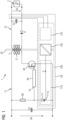
- the switching of the current pulses is preferably controlled by a control device 30 of the voltage converter 1 by means of a switching element 40 which is electrically connected in series with the primary winding 21 of the operating transformer 20 and which is switched on and off by the control device 30.
- the voltage converter 1 has, in particular for monitoring its correct operation, a monitoring device 50 with at least one monitoring channel 100.
- the supply voltage of the control device 30 is formed by the input voltage Ue of the voltage converter 1 and the activation of the fuse element 60 is achieved by connecting the fuse element 60 to ground potential or by applying the input voltage Ue of the voltage converter 1 to the fuse element 60.
- the fuse element 60 can, for example, be a fuse that is triggered when the input voltage Ue is applied. Alternatively, other embodiments for the fuse element 60 are also possible: For example, the fuse element 60 can also be a switch that is switched off when the primary switching element 111 is triggered and can be manually switched back on after being switched off.
- the Figure 2 shows an embodiment of the monitoring channel 100 of the voltage converter 1 according to Figure 1 in more detail.
- the secondary unit 120 shown on the left comprises, on the input side, a secondary unit-side voltage divider formed by two series-connected resistors R1 and R2, to which the output voltage Ua of the voltage converter 1 is applied.
- a comparison element 121 is connected to the center connection of the voltage divider, to which a logic circuit 122 is arranged. When activated, the logic circuit 122 can switch on a downstream secondary switching element 123, which is connected to a connection side 131 of the transformer 130, a secondary unit-side Resistor R3 and a secondary unit-side diode D1 in series.
- the resistors R1 and R2, the comparison element 121 and the logic circuit 122 form a comparison circuit V120 of the secondary unit 120 suitable for monitoring the output voltage.
- a primary-side diode D2 and a primary-side parallel circuit are connected to the other terminal 132 of the transformer 130.
- the latter parallel circuit comprises a capacitor C3 and a series circuit of two resistors R4 and R5, which form a voltage divider.
- the ignition input 111a of the primary switching element 111 is connected to the center terminal of the voltage divider according to Figure 1 connected.
- the voltage divider formed by resistors R4 and R5 defines the voltage applied to the primary switching element 111 and thus the trigger threshold for the primary switching element 111.
- the output voltage Ua is below a shutdown threshold defined by a maximum voltage value.
- the voltage drop across resistor R2 is insufficient to reach or exceed a reference voltage specified by comparison element 121, which corresponds to the maximum voltage value.
- Logic circuit 122 is therefore not activated, and secondary switching element 123 remains non-conductive, and no trigger signal S is transmitted for shutdown.
- the output voltage Ua exceeds the shutdown threshold, so that the voltage drop across resistor R2 exceeds the reference voltage of the comparison element 121.
- the comparison element 121 becomes conductive and thereby activates the logic circuit 122, which in turn switches on the secondary switching element 123, thereby placing it in a conductive state.
- a current flows through the transformer 130.
- the energy pulse resulting from the current flow through the transformer 130 is rectified in the primary unit 110 via the diode D2 and buffered in the capacitor C1.
- the voltage across the capacitor C1 leads to the trigger signal S, which fires the primary switching element 111 and the supply voltage or the input voltage Ue from the control device 30 according to Figure 1 disconnects, thereby switching off the energy transmission via the operating transformer 20.
- Resistor R3 in secondary unit 120 defines and limits the current flow through transformer 130 and can be dimensioned to suit the application.
- Diode D1 on the secondary unit side ensures decoupling of secondary unit 120 from the other components of voltage converter 1.
- the Figure 3 shows a second embodiment of a voltage converter 1 according to the invention.
- the monitoring device 50 comprises three monitoring channels 100, each of which is connected to the fuse element 60 and each of which can connect the fuse element 60 to ground.
- each of the monitoring channels 100 is equipped with a primary switching element 111 that can establish the corresponding electrical connection between the fuse element 60 and the ground connection.
- the primary switching elements 111 are preferably electrically connected in parallel; this redundant design achieves a particularly high degree of reliability of the monitoring device 50 because each of the primary switching elements 111 can trigger the fuse element 60.
- the monitoring channels 100 can be of identical construction and each with the Figure 2 explained monitoring channel 100 must be identical.
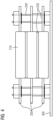
- the Figure 4 shows, for example, that the transformers 130 are in accordance with the Figures 1 to 3 can be planar transformers, each of which is integrated in the form of spiral-shaped conductor tracks in an associated printed circuit board 200.
- the printed circuit boards 200 are preferably stacked vertically (here, this means perpendicular to the circuit board plane of the printed circuit boards 200).
- Each of the planar transformers is arranged on its own circuit board 200 and has its own transformer core 210.
- the circuit boards 200 and the transformer cores 210 are kept vertically spaced apart by electrically insulating spacers 230.
- the printed circuit boards 200 are connected directly or indirectly to the fuse element 60 of the voltage converter 1 via electrically conductive board connectors 240 (cf. Figures 1 to 3 ).
- the fuse element 60 is preferably arranged on a base circuit board 300 carrying the circuit boards 200.
- each monitoring channel 100 can each be arranged on the circuit board 200 carrying the planar transformer of the respective monitoring channel, or alternatively on the base circuit board 300, on which the stack of planar transformers is arranged and which preferably carries the remaining components of the voltage converter 1. It is particularly advantageous if each monitoring channel 100 is arranged as an independent unit on its own circuit board 200, and the monitoring channels form independent modules.
- the Figure 5 shows a further preferred embodiment and arrangement of the transformers 130 in the case that two or more monitoring channels 100 are present, for example for the one in the Figure 3 shown case with three monitoring channels 100 and three transformers 130.
- the transformers are planar transformers that are stacked on top of each other in a multilayer circuit board 200 and are connected to the base circuit board 300 via board connectors 240.
- planar transformers share a common transformer core 210.
- One advantage of a common transformer core 210 is that a single secondary-side trigger signal S of a single monitoring channel 100 can simultaneously trigger a trigger signal S in the primary units 110 of all monitoring channels 100 and thus the primary units of all monitoring channels 100 can each activate the fuse element 60 on the primary side.
- the Figure 6 shows a further preferred embodiment and arrangement of the transformers 130 in the case that two or more monitoring channels 100 are present, for example for the Figure 3 shown case with three monitoring channels 100 and three transformers 130.
- the transformers 130 are coil transformers, each comprising a primary coil 420 and a secondary coil 430 wound on a coil former section 411, 412, and 413 of a coil former 410.
- the primary coil 420 is electrically separated from the secondary coil 430 by an insulation 440.
- the primary coils 420 of the three transformers 130 are radially inward and the secondary coils 430 are arranged radially outward; alternatively, the radial arrangement can also be reversed.
- the coil body sections 411, 412, and 413 of the three transformers 130 are axially offset along the longitudinal axis L of the coil body 410 or arranged adjacent to one another.
- the transformers 130 share a common transformer core 450, which extends axially through a through-hole 414 in the coil body 410.
- An advantage of a common transformer core 450 can also be seen here in the fact that a secondary-side trigger signal S of a single monitoring channel 100 simultaneously triggers a trigger signal S in the primary units of all monitoring channels 100, i.e., all monitoring channels 100 activate the fuse element 60 simultaneously on the primary side.
Landscapes
- Engineering & Computer Science (AREA)
- Power Engineering (AREA)
- Dc-Dc Converters (AREA)
Applications Claiming Priority (1)
| Application Number | Priority Date | Filing Date | Title |
|---|---|---|---|
| DE102023209496.7A DE102023209496A1 (de) | 2023-09-28 | 2023-09-28 | Spannungswandler und Verfahren zum Betreiben eines Spannungswandlers |
Publications (1)
| Publication Number | Publication Date |
|---|---|
| EP4531260A1 true EP4531260A1 (fr) | 2025-04-02 |
Family
ID=92895602
Family Applications (1)
| Application Number | Title | Priority Date | Filing Date |
|---|---|---|---|
| EP24202013.9A Pending EP4531260A1 (fr) | 2023-09-28 | 2024-09-23 | Convertisseur de tension et procédé de fonctionnement d'un convertisseur de tension |
Country Status (2)
| Country | Link |
|---|---|
| EP (1) | EP4531260A1 (fr) |
| DE (1) | DE102023209496A1 (fr) |
Citations (3)
| Publication number | Priority date | Publication date | Assignee | Title |
|---|---|---|---|---|
| JPH06284714A (ja) * | 1993-03-31 | 1994-10-07 | Sumitomo Metal Ind Ltd | 絶縁型dc−dcコンバータ |
| DE102016109649A1 (de) | 2016-05-25 | 2017-11-30 | Endress + Hauser Gmbh + Co. Kg | Primärgetaktetes Schaltnetzeil |
| US11303198B2 (en) * | 2018-12-12 | 2022-04-12 | Silergy Semiconductor Technology (Hangzhou) Ltd | Isolated switching converter, control circuit and control method thereof |
Family Cites Families (5)
| Publication number | Priority date | Publication date | Assignee | Title |
|---|---|---|---|---|
| US3215896A (en) * | 1962-10-04 | 1965-11-02 | Gen Electric | Fast response overload protection circuit |
| US3758840A (en) * | 1972-05-15 | 1973-09-11 | Hewlett Packard Co | Power supply utilizing improved voltage regulation |
| DE102011005416A1 (de) * | 2011-03-11 | 2012-09-13 | Robert Bosch Gmbh | Steuerung einer Versorgungsspannung |
| DE102014118982A1 (de) * | 2014-12-18 | 2016-06-23 | Turck Holding Gmbh | Schutzschaltung |
| DE102021109645A1 (de) * | 2020-04-22 | 2021-10-28 | Phoenix Contact Gmbh & Co. Kg | Energieversorgungsvorrichtung mit sicherheitsgerichteter Abschaltung sowie Verfahren zum Abschalten einer Energieversorgungsvorrichtung |
-
2023
- 2023-09-28 DE DE102023209496.7A patent/DE102023209496A1/de not_active Withdrawn
-
2024
- 2024-09-23 EP EP24202013.9A patent/EP4531260A1/fr active Pending
Patent Citations (3)
| Publication number | Priority date | Publication date | Assignee | Title |
|---|---|---|---|---|
| JPH06284714A (ja) * | 1993-03-31 | 1994-10-07 | Sumitomo Metal Ind Ltd | 絶縁型dc−dcコンバータ |
| DE102016109649A1 (de) | 2016-05-25 | 2017-11-30 | Endress + Hauser Gmbh + Co. Kg | Primärgetaktetes Schaltnetzeil |
| US11303198B2 (en) * | 2018-12-12 | 2022-04-12 | Silergy Semiconductor Technology (Hangzhou) Ltd | Isolated switching converter, control circuit and control method thereof |
Also Published As
| Publication number | Publication date |
|---|---|
| DE102023209496A1 (de) | 2025-04-03 |
Similar Documents
| Publication | Publication Date | Title |
|---|---|---|
| DE69408811T2 (de) | Gleichstrom-Hochleistungsschalter | |
| EP1965482B1 (fr) | Réseau ASI pour des zones en danger d'explosion | |
| DE102016100758A1 (de) | Trennvorrichtung für einen photovoltaischen String, Solaranlage und Betriebsverfahren für eine Solaranlage mit photovoltaischem String | |
| WO2015110142A1 (fr) | Dispositif de commutation d'un courant continu | |
| EP1805887B1 (fr) | Systeme d'excitation statique pour une generatrice et procede de fonctionnement d'un systeme d'excitation de ce type | |
| DE102019211968A1 (de) | Ansteuerverfahren für einen Gleichspannungswandler und Gleichspannungswandler | |
| DE2812632A1 (de) | Steuerkreis fuer einen vollsteuergate- thyristor | |
| EP3247015B2 (fr) | Dispositif d'alimentation électrique et procédé de fonctionnement d'un dispositif d'alimentation électrique | |
| DE602004002391T2 (de) | Generator für lichtbogenschweissvorrichtung mit hochleistungsfaktor | |
| EP2234259A1 (fr) | Dispositif d'allumage et de mise en service de tiges de silicium | |
| WO2007128675A1 (fr) | Système pour transmettre des signaux et de l'énergie destiné à des composants électroniques à semi-conducteurs de puissance et procédé de transmission | |
| DE102023209496A1 (de) | Spannungswandler und Verfahren zum Betreiben eines Spannungswandlers | |
| EP1014531B1 (fr) | Appareil d'alimentation en énergie électrique pour composants électroniques anti-déflagrant | |
| DE102019207968B4 (de) | Vorrichtung zur induktiven Übertragung elektrischer Energie | |
| DE3201296A1 (de) | Transistoranordnung | |
| EP2385608B1 (fr) | Entraînement de meuble électro-motorisé doté d'un dispositif d'alimentation en énergie | |
| DE4419958C1 (de) | Schaltungsanordnung zur redundanten Stromversorgung | |
| DE2461564A1 (de) | Einrichtung zur parallelankopplung fuer tonfrequenz-rundsteuersendeanlagen | |
| DE3116447A1 (de) | "impulsgenerator" | |
| WO2007143975A2 (fr) | Procédé de transmission galvaniquement séparée d'énergie et d'informations entre deux unités de circuit électronique | |
| DE102019121619A1 (de) | Solarmodul, Solarzellenanordnung und Verfahren zur Bereitstellung von elektrischer Energie | |
| DE102020117504A1 (de) | Verfahren zur Verringerung des Einschaltstroms eines elektrischen Geräts sowie elektrisches Gerät | |
| DE69315753T2 (de) | Schaltung für Fehlerstromschutzschalter | |
| DE3511967A1 (de) | Einrichtung zur kontrolle von elektrischen verbrauchern in kraftfahrzeugen | |
| CH666771A5 (de) | Schaltungsanordnung fuer einen elektronischen rundsteuerempfaenger. |
Legal Events
| Date | Code | Title | Description |
|---|---|---|---|
| PUAI | Public reference made under article 153(3) epc to a published international application that has entered the european phase |
Free format text: ORIGINAL CODE: 0009012 |
|
| STAA | Information on the status of an ep patent application or granted ep patent |
Free format text: STATUS: THE APPLICATION HAS BEEN PUBLISHED |
|
| STAA | Information on the status of an ep patent application or granted ep patent |
Free format text: STATUS: REQUEST FOR EXAMINATION WAS MADE |
|
| AK | Designated contracting states |
Kind code of ref document: A1 Designated state(s): AL AT BE BG CH CY CZ DE DK EE ES FI FR GB GR HR HU IE IS IT LI LT LU LV MC ME MK MT NL NO PL PT RO RS SE SI SK SM TR |
|
| 17P | Request for examination filed |
Effective date: 20250320 |
|
| RAP3 | Party data changed (applicant data changed or rights of an application transferred) |
Owner name: SIEMENS MOBILITY GMBH |